Ropox QUICKWASH COMPLETE User manual

ROPOX QUICKWASH COMPLETE
User manual
This manual should always be in close proximity of the
product.
TF 200.01.0010_ENG / Date 05-03-2021

TF 200.01.0010_ENG
2
Table of content
1. Symbols used in this manual.................................................................................................................. 3
2. General safety........................................................................................................................................... 3
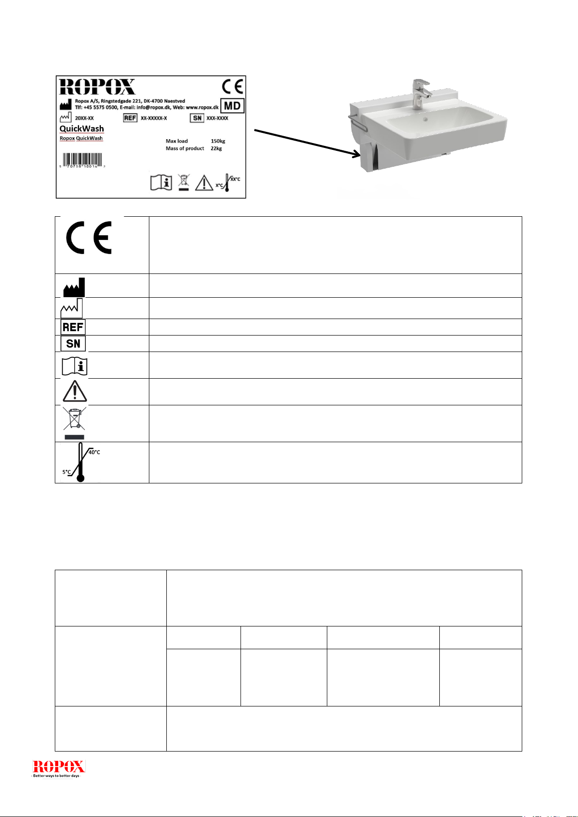
2.1 Product Unit label ...................................................................................................................... 5
3. General requirements .............................................................................................................................. 5
3.1 Product information ....................................................................................................................... 5
3.2 Product description ....................................................................................................................... 6
3.3 Intended use.................................................................................................................................. 6
3.4 Intended operator .......................................................................................................................... 6
3.5 Essential performance .................................................................................................................. 6
3.6 Non clinical functions .................................................................................................................... 6
3.8 Clinical functions ........................................................................................................................... 6
3.9 Product dimensions....................................................................................................................... 7
............................................................................................................................................................. 9
4. Instructions for use .................................................................................................................................. 9
4.1 Installation Interfaces................................................................................................................. 9
4.1.1 Construction ........................................................................................................................... 9
4.1.2 Plumbing................................................................................................................................. 9
4.2 Mounting Instructions............................................................................................................... 10
4.2.1 Determine mounting height .................................................................................................. 10
4.2.2 Drill holes and mount unit on wall......................................................................................... 11
4.2.3 Mount wash basin to unit...................................................................................................... 11
4.2.4 Attach plumbing and faucet .................................................................................................. 12
4.2.5 Attach cover plate................................................................................................................. 13
4.2.6 Final test of completed unit .................................................................................................. 13
4.3 Operating the product .............................................................................................................. 14
Height adjustment.......................................................................................................................... 14
4.4 Residual risk ............................................................................................................................ 15
5. Cleaning .................................................................................................................................................. 16
6. Maintenance............................................................................................................................................ 16
6.1 Periodic maintenance .............................................................................................................. 16
7. Components part list.............................................................................................................................. 17
8. Environmental protection...................................................................................................................... 18
9. Accident reporting.................................................................................................................................... 18

TF 200.01.0010_ENG
3
1. Symbols used in this manual
Warning Symbol
Indication of potentially hazardous situation. If not avoided it can
result in serious injury or death.
Caution Symbol
Indication of potentially hazardous situation which may result in
minor or moderate injury.
It may also be used to alert against unsafe practices.
Notification Symbol
This symbol is used to notify correct use and handling of the
product.
2. General safety
This manual must be read and understood before use.
Always keep this manual in close proximity of the product.
The use, installation and service of this product must be in
compliance with this manual to avoid accidents and serious
personal injury.
Never use or handle this product in other ways specified in
this manual as it can result in personal safety hazards and/or
cause damage to the product.
Persons installing and/or using this product either as operator
or user should have the necessary safety information and
access to this manual.
Do not perform repairs, disassembly or assembly operations,
add-ons, re-adjustments or modification of the product
beyond what is described in this manual. These must be
carried out by Ropox or Ropox authorized personnel. Do not
perform service while in use.

TF 200.01.0010_ENG
4
This appliance can be used by children aged from 8 years
and above and persons with reduced physical, sensory or
mental capabilities or lack of experience and knowledge if
they have been given supervision or instruction concerning
use of the appliance in a safe way and understand the
hazards involved. Children shall not play with the appliance.
Cleaning and user maintenance shall not be made by
children without supervision.
Do not use the product if it has defects or have become
damaged before being repaired or replaced.
The information in this manual is based on correct installation
in accordance with installation instructions for this product.
Ropox cannot be held liable if the product is used in any way
that differs from stated in this manual and/or installation
instruction.
Ropox reserve the right to amend this manual and reference
documents without prior notice.

TF 200.01.0010_ENG
5
2.1 Product Unit label
3. General requirements
3.1 Product information
Manufacturer:
Ropox A/S
Ringstedgade 221, DK-4700 Naestved
+45 55 75 05 00
Email: Info@ropox.com
Product models
Part number
Model
Configuration
UDI
40-42121-1
QuickWash
Complete
Release lever on left-
hand side
57075810014R6
Expected service life
according to ISO
17966:2016
5 years
This product is CE-marked in accordance with:
European Medical Device Regulation (EU)2017/745
Manufacturer name and address
Date of production
Stock number
Serial number
Consult manual before use
Consult manual for important safety related information, warnings and safety
precautions.
Do not dispose as unsorted municipal waste. Product must be returned to a
designated recycling station.
Operating and storing temperatures may not exceed 5-40C°

TF 200.01.0010_ENG
6
MDR Class
2017/745
Class I
Intended environments
This product is to be used only in:
Proffesional Healtcare Environment
Homecare Environment
Maximum user weight
according to ISO
17966
150 kg
Height adjustment
140 mm up/down, 100 mm in/out
Ambient temperature
5-40C° Operation and storage
3.2 Product description
Ropox QuickWash is a small height adjustable system for a washbasin. It can be height adjusted 14 cm,
while also projecting the attached washbasin 20cm out from the wall for added legroom.
3.3 Intended use
Ropox QuickWash is intended for use in both homecare and professional healthcare environments.
Adjusting the height and depth of the wash basin, accommodates ergonomical requirements, stemming from
the difference in height between seated wheelchair users and standing users.
Ropox QuickWash is not intended for playing with or as an exercise-equipment.
3.4 Intended operator
The intended operator may include all that have read and understood this manual exempt kids.
3.5 Essential performance
The device does not have any function related to basic safety or essential performance. In
case of loss or degradation of performance, the user can still wash their hands or chose not to.
3.6 Non-clinical functions
Height adjusting offers better ergonomics to the user.
3.8 Clinical functions
This product do not offer clinical benefit for patients, when used as intended by the manufacturer.

TF 200.01.0010_ENG
7
3.9 Product dimensions
40-42120 – QuickWash Unit
NB: All dimensions are in mm

TF 200.01.0010_ENG
8
40-42121 – QuickWash Complete
Up position
Down position
“X” measurement is based on an individual measurement of the specific wheelchair-seated end-
user of the product. See mounting instructions for more details.
NB: All dimensions are in mm

TF 200.01.0010_ENG
9
4. Instructions for use
4.1 Installation Interfaces
4.1.1 Construction
The wall must be of a suitable material for screws and approved
for wet rooms. Note the maximum tensile load of the top
screws and ensure that both the structure of the wall and
choice of rawl plugs can withstand the force.
The grey-shaded area states the minimum area for
reinforcement of the wall.
Load tested in accordance with DS/ISO 17966:2016
max. user weight: 150kg
Max. tensile load of top screws: 76 kg (745N)
4.1.2 Plumbing
The drain is Ø32 (1 ¼”).
The water supply ends with 2 (two) 90° stop valves with
½” outside thread pointing upward.
All hoses for water and drain installations must be flexible
to ensure free and unhindered adjustments within the
height adjustment range of cm (the upper side of the
washbasin).
NOTE:
All dimensions are based on a washbasin height
referenced off the individual user’s measurements. Those
measurements are based on the height from the floor to
the top of the user’s legs, when seated in their
wheelchair. If a drastic change of this height is required,
the recommended dimensions must be changed
accordingly.

TF 200.01.0010_ENG
10
4.2 Mounting Instructions
Prior to the installation, please make sure that all parts have been provided in accordance with the
list of components (Section 7).
4.2.1 Determine mounting height
A) With the primary user seated in their wheelchair, measure
the height to the top of user’s legs (X). This measurement
ensures the correct height of the unit and provides proper
clearance when the unit is in the down position. Make sure to
measure at the highest point (If the wheelchair has armrests,
consider if these will be in the way and if the height of the unit
should instead be set according to the armrests.)
If the user is not available for taking the measurement, the
recommended default value of X is 670 mm (26,5”).
A) Transfer X-measurement to wall
B) Place the bottom of the
template on the line and
mark out the positions of the
mounting holes. This will
provide approximately 10-
15mm of clearance between
the bottom of the wash basin
and the top of the user’s
legs.

TF 200.01.0010_ENG
11
4.2.2 Drill holes and mount unit on wall
A) Drill holes at the 8 marked locations
on the wall
A) B) Insert appropriate wall plugs
fitting of the type of wall in which the
product is to be installed
B) C) Mount the QuickWash unit on
the wall using the included frame
screws *7,5x75mm
C) D) Check that the unit is level
D) E) Tighten the screws where
needed
4.2.3 Mount wash basin to unit
A) Attach bolts from the backside of the unit
and fix with washers and nuts.
B) After mounting the wash basin, please
check the following:
1: That the basin is level
2: That the basin is centered compared to
the unit
3: That the release lever works and allows
lowering of the unit
4: That the unit stays in place in both top
and bottom position
5: That the bottom position fits well for the
user, with comfortable level of clearance.

TF 200.01.0010_ENG
12
4.2.4 Attach plumbing and faucet

TF 200.01.0010_ENG
13
4.2.5 Attach cover plate
A) Lower the unit to the down position
by releasing the grey lever/arm on the
side of the unit
B) Slide cover on from above. Take care
not to bend the “fingers” on the sides
A) Position the bottom tabs of the cover
beneath the wall-bracket and fix in place
with the 4 dome-headed M5 screws
B) Check that the unit moves freely up
and down and does not interfere with
the cover
4.2.6 Final test of completed unit
Everything should now be installed. Please follow the checklist below to make sure that everything is working
as expected.
1) Test that the unit feels sturdy and secure on the wall
2) Check that the unit moves smoothly and unobstructed in its full range of movement, both up and
down
3) Check that the unit fits the end user and is comfortable to use when in the lowest position (that
the bottom of the sink does not severely interfere with the user’s legs or knees)
4) Check that the locking pin clicks in place when unit is in the up position and that the wash basin
feels securely locked
5) Check that the faucet works and the water drains as it should
6) Check that the flexible plumbing is neat and moves unobstructed when moving the unit up and
down

TF 200.01.0010_ENG
14
4.3 Operating the product
Height adjustment
The washbasin position is adjusted manually. A counterbalance system makes it easy to
lift and lower the wash basin.
Lowering from high to low position
(1) Press the grey release lever on
the left-hand side of the unit
towards the wash basin
(2) While holding down the release
lever, pull the basin downwards
until it reaches the end of travel.
Adjusting from low to high position
Simply push or raise the basin until you hear the locking pin clicking in place.
Warning!
The product should always be able to travel the full range of movement without colliding
with objects. Failing to do so will compromise the product stability.
Special care should be taken in ensuring that no children or adults are sited under the
product as severe injury from entrapment may occur.

TF 200.01.0010_ENG
15
4.4 Residual risk
Warning
Be aware that there are no persons under the wash
basin when it is driven down, as a danger of impact
and head trauma may occur.
Caution
Do not place the hand between the wall and the unit
during unit movement, as a danger clamping may
occur.
Caution
Do not place the hand in the slits of the cover, as a
danger clamping may occur.
Warning
In case of incorrect installation of plumbing parts,
water leaks can occur on the floor, which may
increase the risk of falling.
Warning
Make sure no water is in the basin during
movement. Water may otherwise splash onto floor,
which may increase the risk of falling.

TF 200.01.0010_ENG
16
5. Cleaning
Cleaning can be done with lukewarm water and a suitable all-purpose cleaning agent. Use a cloth or soft
sponge to wash the product. Dry the product of with a wrung cloth.
Notification!
Do not use cleaning agents containing abrasive e.g. scouring powder, steel wool, scouring
sponge.
This product is not designed to be sterilized. Autoclaving and sterilization beyond normal
cleaning as this may possibly change the product safety and function.
Preapproved cleaning agents
Tradename
Solution
Acticlor plus
1000ppm
S90 sanirens
1-3% peracid
FUTUR, Alkalisk rens
1% Solution [pH 9,5]
6. Maintenance
Notification!
Failing to comply with periodic maintenance may result of degrading of product function and
safety.
6.1 Periodic maintenance
Component
Maintenance activity
Maintenance interval
Registration date of
maintenence
Complete Unit
Check fixing to the wall
are still tight and
reliable. If unit has
started to work itself
lose, take action to get
unit tightened and
securely fixed to the wall
again
Every 6 months

TF 200.01.0010_ENG
17
7. Components part list
1 (one) height adjustment unit
40-42120
List of components for Complete models 40-42121
1 (one) washbasin
97001584
1 (one) mixer tap
Oras Saga 3910F
1 (one) plumbing kit
1 (one) Siphon
1 (one) 97001172 Flexible drain hose ø32
2 (two) 97001035 Drain elbow 88,5°
2 (two) 97001012 Nipple ½” to 3/8”
2 (two) 97001123 Connecting hose ½” 0.5m
1 (one) kit of mounting parts for bolt
mounted washbasin
2 (two) bolts M12x65
2 (two) washers
2 (two) Nuts M12
1 (one) set of wall-plugs and frame
screws
1 (one) Cover plate incl.
4 (four) mounting screws

TF 200.01.0010_ENG
18
1 (one) cardboard template for hole
Notification!
Ropox will make parts list and circuit diagrams available for extraordinary maintenance
and repair beyond what is described in this manual. Repair beyond what is described in
this manual may only be done by Ropox designated service personnel.
8. Environmental protection
The product is not intended to be disposed as municipal waste. Proper disassembly, sorting and
disposal of components must be done by waste disposal professionals.
Part
Disposal recommendation
Wash Basin
Ceramic
Main Unit
Steel
Cover
Aluminum
Faucet
Steel
9. Accident reporting
The manufacturer of this product recommends any accident with this product that meets all of the following
criteria reported to the appropriate authority as well as to the manufacturer.
1. There has been or could have been an event
2. The medical device is considered to be a contributing factor to the case, and
3. The event resulted or could have resulted in one of the following outcomes:
•death - a patient, a user or a third party death
•A serious deterioration of a patient's health, a user's or third party health status in the form of:
o1. Life-threatening disease
o2. Lasting damage or injury
o3. Necessary medical or surgical treatment to divert life-threatening illness, permanent injury
o4. fatal death, fetal injury or congenital abnormalities.
This manual suits for next models
2
Table of contents
Other Ropox Bathroom Fixture manuals
Popular Bathroom Fixture manuals by other brands

CLEOPATRA
CLEOPATRA Steam One 9018 70 10 Instructions for use/assembly instructions

Pegasus
Pegasus 735B-0204 Use and care guide

Signature Hardware
Signature Hardware Provincetown 948559 manual

aquabrass
aquabrass Town of Mount Royal 15016 installation guide

rba
rba RBA1882-100-Series Installation, operation and maintenance instructions

Helvex
Helvex RM-15 quick start guide