Rosco Image Spot Mini Series User manual

PLEASE READ & SAVE THESE ORIGINAL INSTRUCTIONS
User Guide
Image Spot®
Mini
This guide applies to the following Rosco Image Spot Mini models:
296201030651 Image Spot Mini 3000K – IP65 - w/o Lens – Black
296201030652 Image Spot Mini 3000K – IP65 - w/o Lens – White
296201055651 Image Spot Mini 5500K – IP65 - w/o Lens – Black
296201055652 Image Spot Mini 5500K – IP65 - w/o Lens – White
2962010T3001 Image Spot Mini 3000K – Track 0-10V/Triac – Black – No Lens
2962010T3002 Image Spot Mini 3000K – Track 0-10V/Triac – White – No Lens
2962010T3003 Image Spot Mini 3000K – Track DMX – Black – No Lens
2962010T3004 Image Spot Mini 3000K – Track DMX – White – No Lens
2962010T5501 Image Spot Mini 5500K – Track 0-10V/Triac – Black – No Lens
2962010T5502 Image Spot Mini 5500K – Track 0-10V/Triac – White – No Lens
2962010T5503 Image Spot Mini 5500K – Track DMX – Black – No Lens
2962010T5504 Image Spot Mini 5500K – Track DMX – White – No Lens
2962010UV651 Image Spot Mini UV - IP65 – w/o Lens – Black
296210000010 Image Spot Mini 0-10V/Triac Driver 15W
296210000DMX Image Spot Mini DMX Driver 36W
www.rosco.com/imagespot-mini 5007481

2

3
TABLE OF CONTENTS
Introduction......................................................................................................................................... 4
Important Safeguards ........................................................................................................................ 4
Unpacking ............................................................................................................................................ 7
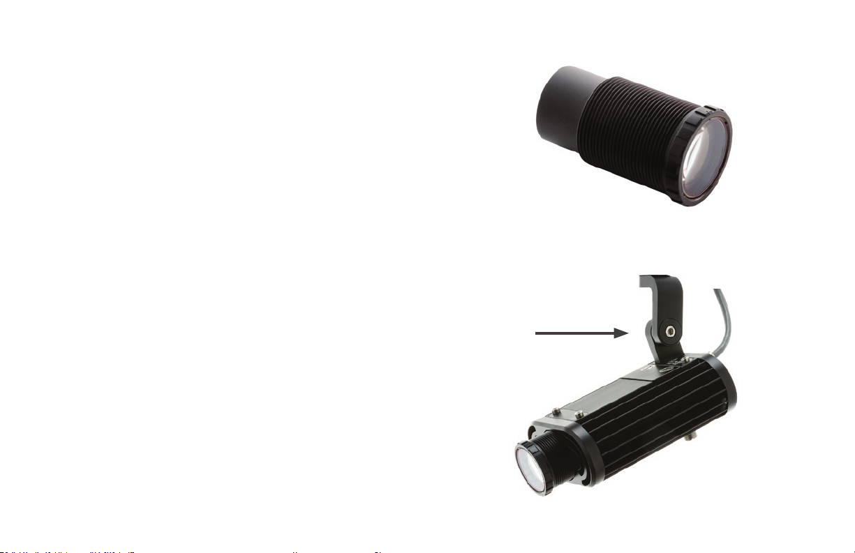
Installing Lens Tube........................................................................................................................... 8
Mounting.............................................................................................................................................. 8
Wiring ................................................................................................................................................... 9
Dimming Control ............................................................................................................................. 12
Focusing ............................................................................................................................................ 12
Gobo Projection............................................................................................................................... 13
Dichroic Color Filters.......................................................................................................................14
Accessories ....................................................................................................................................... 15
Ordering Gobos & Permacolor Filters..........................................................................................16
Technical Specifications ................................................................................................................. 18
Warranty ........................................................................................................................................... 20
Information and specifications in this document are subject to change without notice.
Rosco assumes no responsibility or liability for any errors or inaccuracies that may appear in this manual.
Image Spot®Mini User Guide Copyright ©2019 by Rosco
User Guide

4
INTRODUCTION
Congratulations on your purchase of a Rosco Image Spot Mini projector. Designed to provide crystal-clear
imaging and spot illumination, the Image Spot Mini is quick and easy to set up with convenient on-board
dimming or remote controls.
To ensure efficient and safe operation, please take a few moments to read this manual completely.
IMPORTANT SAFEGUARDS
The symbols below are used throughout this manual to identify important safety information. Heed all
warnings and safety information.
Warning, Danger or Caution
Risk of Personal Injury
Risk of Electric Shock
Risk of severe electric shock

5
PREVENTING ELECTRIC SHOCK
• This system uses mains drivers that connect to electrical power at 100-277VAC. When directly contacted,
such voltages are hazardous to human life. Follow all local electrical codes and take precautions when using
this product.
• Use only extension cords that are of appropriate length and are rated for Image Spot Mini’s specified
voltage and current. If an extension cord shows signs of wear or gets warm to the touch, discontinue its
use and obtain a cord with a higher current rating. Improper extension cords are hazardous and may result
in poor performance due to excessive voltage drop.
• Disconnect unit from power source before servicing and when not in use.

6
MAINTAINING SAFE OPERATION
• Do not look directly into the Image Spot Mini projector. Prolonged exposure to the light beam can cause
damage to eyesight.
• Use only Rosco spare parts and accessories so as to not void the product warranty.
• The Image Spot Mini’s surface temperature can approach 150ºF (65ºC) during operation. Keep minimum
4 inches (10cm) distance away from flammable materials / objects. Contact with the fixture during, or
immediately following, operation may result in burns.
• Allow the unit to cool before attempting to service.
• Rosco Image Spot Mini must only be serviced by a qualified technician.
• Rosco Image Spot Mini is not certified for use in hazardous locations.
• Rosco Image Spot Mini is designed for operation within the range of -4° to 122°F (-25° to +50°C).
• Ensure Rosco Image Spot Mini is stored within the range of -13° to 140°F (-25° to +60°C).
WARNING: Do not look directly into the UV light during operation. Eye and skin exposure to UV light can
cause severe damage to humans and animals. Take every precaution to limit exposure to UV light (including
the use of UV-blocking eye protection).

7
UNPACKING
Carefully remove the unit from the box.
Do not attempt to operate Rosco Image Spot Mini projector if there are any signs of physical damage. In case
of damage, contact your local Rosco dealer.
Your Rosco Image Spot Mini projector requires that an Image Spot Mini focusing lens tube (purchased
separately) be inserted into the opening on the front of the unit prior to operation.
Three lens options are available, providing Narrow, Medium and Wide beam angles. The size of the image or
the beam angle can be adjusted by replacing the lens tube with an alternate size:
Item No296220000111 Image Spot Mini Narrow Angle Lens Optic/ 11º - Black
Item No296220000171 Image Spot Mini Medium Angle Lens Optic/ 17-º - Black
Item No296220000251 Image Spot Mini Wide Angle Lens Optic/ 25º - Black
Item No296220000112 Image Spot Mini Narrow Angle Lens Optic/ 11º - Silver
Item No296220000172 Image Spot Mini Medium Angle Lens Optic/ 17º - Silver
Item No296220000252 Image Spot Mini Wide Angle Lens Optic/ 25º - Silver

8
INSTALLING LENS TUBE
Gently insert the end of the lens tube into the opening on the
front of the projector. Rotate several turns to engage the threads.
Once the projector has received power, the lens tube can be
further rotated to adjust the focus of the projected image.
MOUNTING
The Image Spot Mini projector can be installed in the desired
location via the center hole in the yoke. Adjust and fix the tilt of
the projector via the hex screw on the side of the yoke.

9
WIRING (Non Track Version)
Your Rosco Image Spot Mini projector will arrive with an unterminated power cord attached to the unit.
Wiring to a Rosco-supplied driver and the driver to line voltage should be performed by a qualified electrician
and is the responsibility of the installer or end user.
Connect the AC Mains power supply, Control signal leads (0-10V DC, Triac or DMX) and lead wires from the
Image Spot Mini projector to the selected driver as follows:
Image Spot Mini Wiring For 0-10V LED Dimmer
0-10V
LED DIMMER
Black
White
Black
Black
Red
Green
White
Red
White
Black
Grey
Purple
DN Wiring Dia 1 V3
IMAGE SPOT MINI
0-10V/TRIAC
DRIVER
L : Black
N: White
LED+ : Red
LED - : Black
DIM+: Purple
DIM - : Grey

10
Image Spot Mini Wiring For On-Board Dimmer
Image Spot Mini Wiring For DMX Controller
DN Wiring Dia 2 V3
Black
Black
Red
White
Green
Red
White
Grey
Purple
IMAGE SPOT MINI
0-10V/TRIAC
DRIVER Black
White
4
3
2
1
8
7
6
5
Black
Red
DMX Driver
LED -
LED +
ISET2
ISET1
GND
DMX-
DMX +
3
ON
21
IMAGE SPOT MINI
DMX CONTROLLER
Black
DN Wiring Dia 3 V4
L : Black
N: White
LED + : Red
LED - : Black

11
The current will be preset on the LTech DMX driver to 1050mA:
Note: the suggested current is 1050mA, any variaon may result in under performance or a shortened LED
life cycle, and may void warranty.
Ensure the correct power connecons have been made to the Image Spot Mini projector. The xture will
immediately illuminate upon receiving power and a valid control signal.

12
DIMMING CONTROL
The Rosco Image Spot Mini projector offers two modes of control:
Manual dimming operation or user-supplied 0-10V, Triac or DMX512
data input.
In Manual mode the Image Spot Mini’s beam intensity can be adjusted
via the dimming knob on the rear panel. Turn the knob clockwise for
brighter output and counter-clockwise for dimmer output.
When using 0-10V, Triac or DMX dimming controls, ensure that the
proper Image Spot Mini driver has been ordered and that the proper
lead wire connections have been made (see diagrams on page 9).
DMX control requires that a DMX address be established for each projector. A single channel is required for
output intensity control via DMX. RDM protocol can be used to change the DMX address from the factory
default 001. The controller supports DMX512 bi-directional communication.
FOCUSING
The focus can be adjusted by rotating the lens tube clockwise or counter-clockwise.
Due to the ultra-clear optics of the Image Spot Mini projector, it is advised to keep the optic path clean of
dust and debris. Use a non-abrasive micro-fiber cloth with Rosco Lens Cleaner to clean the Image Spot Mini
lenses and any glass gobos or Permacolor dichroic glass filters you may have installed.
Dimming Knob

13
GOBO PROJECTION
Prior to operating the Image Spot Mini projector insert an Image
Spot Mini gobo into the gobo cassette located on the underside of
the fixture. Gobos with logos or other oriented graphics should be
inserted upside down and backwards for proper projection.
Check to ensure the gobos are free of dust, fingerprints and other
residue prior to inserting the cassette into the accessory slot.
Be sure to tighten the thumb screws on the gobo cassette after re-
inserting to maintain protection from dust and moisture. A flat tipped
screw driver can be used for additional torque to tighten the thumb
screws.
For optimum image quality, use Rosco Image Spot Mini gobos, which
feature custom bezels that fit securely inside the Image Spot Mini
gobo cassette.
To avoid possible ingress of dirt and moisture when changing gobos, orient the Image Spot Mini projector with
the gobo cassee on the underside of the unit whenever possible.

14
DICHROIC COLOR FILTERS
Rosco Permacolor dichroic filters are available to provide fully customizable, long-term color options for your
Image Spot Mini. For optimal performance and installation, specify Image Spot Mini Permacolor Filters that
feature custom bezels to fit securely inside the Image Spot Mini gobo cassette.
Install the Image Spot Mini Permacolor Filter into the gobo cassette. The gobo cassette is deep enough to
accept both an Image Spot Mini Gobo and an Image Spot Mini Permacolor Filter. It is recommended that the
Permacolor Filter be installed on the “lamp-side” of the two. When properly installed, the order should be
lamp -> Image Spot Mini Permacolor Filter -> Image Spot Mini Gobo -> Lens Tube.

15
ACCESSORIES
Item Number Description
296210000010 Image Spot Mini 0-10V/Triac Driver 15W
296210000DMX Image Spot Mini DMX Driver 36W
296220000111 Image Spot Mini Narrow Angle Lens Optic / 11º - Black
296220000171 Image Spot Mini Medium Angle Lens Optic / 17º - Black
296220000251 Image Spot Mini Wide Angle Lens Optic / 25º - Black
296220000112 Image Spot Mini Narrow Angle Lens Optic / 11º - Silver
296220000172 Image Spot Mini Medium Angle Lens Optic / 17º - Silver
296220000252 Image Spot Mini Wide Angle Lens Optic / 25º - Silver
855072020008 Rosco Lens Cleaner 8oz
855072040406 Lens Tissue - 4” X 6” Pad (100 Sheets)
296220000022 Image Spot Mini Cable Cover - Black
296220000023 Image Spot Mini Cable Cover - White
296210000006 Image Spot Mini Driver Enclosure IP65 - Black
296220000020 Image Spot Mini Iris Accessory – Black
296220000021 Image Spot Mini Iris Accessory – White
296220000010 Image Spot Mini Framing Shutter Accessory – Black
296220000011 Image Spot Mini Framing Shutter Accessory – White

16
ORDERING GOBOS & PERMACOLOR FILTERS
Gobos and Permacolor Dichroic Filters for the Image Spot Mini projector can be easily ordered through any
Rosco dealer. Visit www.rosco.com to locate the dealer nearest you and provide them with the information
below.
Standard Gobos
250XXXXX0999T Image Spot Mini Standard Gobo, XXXXX = the five digit standard gobo number
Custom Gobos
25072101MINI Image Spot Mini Custom Steel Gobo 1st Original
2507220CMINI Image Spot Mini Custom Steel Copy
260CUSBWMINI Image Spot Mini Custom B&W Glass Gobo Original
260CUSBCMINI Image Spot Mini Custom B&W Copy
260CUS1CMINI Image Spot Mini Custom One-Color Glass Gobo Original
260CUS1CDMIN Image Spot Mini Custom One-Color Copy
260CUS2CMINI Image Spot Mini Custom Two-Color Glass Gobo Original
260CUS2CCMIN Image Spot Mini Custom Two-Color Copy
260CUS3CMINI Image Spot Mini Custom 3 Color Glass Gobo Original
260CUS3CCMIN Image Spot Mini Custom 3 Color Copy
260CUSMCMINI Image Spot Mini Custom Multi-Color Glass Gobo Original
260CUSMCCMIN Image Spot Mini Custom Multi-Color Copy

17
Permacolor Dichroic Filters
1203XXXXMINI Image Spot Mini Permacolor Dichroic Glass Filter, XXXX = the four digit color
(includes bezel)
For assistance ordering or specifying gobos or Permacolor filters for the Image Spot Mini, please contact our
Gobo Customer Service Centers:
Outside of the US: 512-388-5299
EMEA +44 (0)20 8659 2300 salesadmin@rosco.com

18
TECHNICAL SPECIFICATIONS
Luminaire
Input Voltage: 14Vdc, 1050mA
Maximum Power Consumption: 14 Watts at maximum output
Output: 650 lm (3000k)
1050 lm (5500k)
2,250 mW (UV)
Drivers
Protocol: Mains Dim / 0-10V / Non-dim / DMX RDM
Input Voltage: 100-277VAC (Triac control is 120 VAC compatible)
Output: 8-14Vdc
Power Consumption: 14.7W @ 1050mA
Class: II
LED’s:
3000K / 98+ CRI or 5500K / 75+ CRI
LM79-08 Lumen Maintenance: 90,000 hours @ 50°C (LM80)
UV (365nm peak wavelength with custom dichroic filter
LM79-08 Lumen Maintenance: 20,000 hours @ 25°C

19
Power/Data Connection: 2m (6-ft) Insulated Cable/Gland (IP65), unterminated
Operating Temp.: -13° F to 122° F (-25° C to 50° C)
Dimensions: 4.7 in x 3.4 in x 1.9 in (119 mm x 84.2 mm x 48 mm) excluding yoke
5.17 in x 3.5 in x 9.57 in (131.2 mm x 89 mm x 243 mm) including pendant
Weight: 2.2 lbs (1.0 kg) – Yoke version
4.0 lbs (1.81 kg) – Pendant Track Mount version
Housing: Anodized Aluminum Extrusion
Approvals: ETL / UL Standard 2018 Low Voltage Lighting Systems
ETL / UL Standard 1574 Track Lighting Systems
ETL / CSA Standard C22.2 #250 Luminaires
ETL / CSA Standard C22.2 #250.570 Track Lighting
CE
Ratings: IP65/Damp Environments
Environmental: Disposal of Old Electrical & Electronic Equipment
This symbol on the product or on its
packaging indicates that this product
shall not be treated as household waste.

20
3-YEAR LIMITED WARRANTY
Rosco Laboratories warrants to the first retail purchaser that this Product will be free from defects in
workmanship and material for a period of three years from the date of original purchase.
For warranty service you must be able to provide proof of purchase. Should this Product prove defective
during the warranty period, please contact your local Rosco office for Return Authorization. No warranty
service will be performed without Return Authorization.
At Rosco’s sole discretion, covered Products will be repaired or replaced with new or refurbished equipment
or a model of like kind and quality. Exchanged or replaced parts and Products assume the remaining warranty
period of the original product covered by this limited warranty. You are responsible for securely packaging
the defective Product and returning it to Rosco as per the instructions of the Return Authorization. Within
North America, Rosco will ship the repaired or replaced Product to you freight prepaid. Shipments to other
locations will be made freight collect.
This warranty is non-transferable and does not extend beyond the first retail purchase of the Product.
This warranty does not cover damage to the Rosco Product caused by parts not manufactured, distributed or
certified by Rosco.
Rosco is not obligated to provide warranty service should the Product fail to be properly maintained or fail
to function properly as a result of misuse, abuse, improper installation, neglect, improper shipping, damage
caused by disasters such as flood, fire and lightning, improper electrical current or unauthorized service
repairs other than those by a Rosco Authorized Servicer.
Table of contents
Other Rosco Lighting Equipment manuals

Rosco
Rosco BRAQ CUBE User manual

Rosco
Rosco DMG DASH User manual

Rosco
Rosco MIXBOOK User manual

Rosco
Rosco DMG DASH User manual

Rosco
Rosco GAM SX4 LOOP TRAY Instruction sheet

Rosco
Rosco RevoPro User manual

Rosco
Rosco DMG LUMIERE Maxi Mix User manual

Rosco
Rosco RoscoLED VariWhite Gaffer Kit User manual

Rosco
Rosco myMIX CONNECT User manual

Rosco
Rosco MIRO CUBE 2 User manual