INSTALLATION INSTRUCTIONS
The Model 2721 Outfeed Table Support Kit is designed for use with Rousseau 2720 Outfeed Table and the Bosch 4000 and
4100 table saw. The Angle Brackets and Support Rail mount to existing tapped holes under the saw top. The 12” Adjustable
Legs are a modification to the 2720 Outfeed Table. This modification requires the drilling of one 5/16 hole in each of the
table’s legs for a weld nut and set screw to hold the Adjustment Leg in place. Step-by-step instructions are below.
INSTALLING SUPPORT RAIL
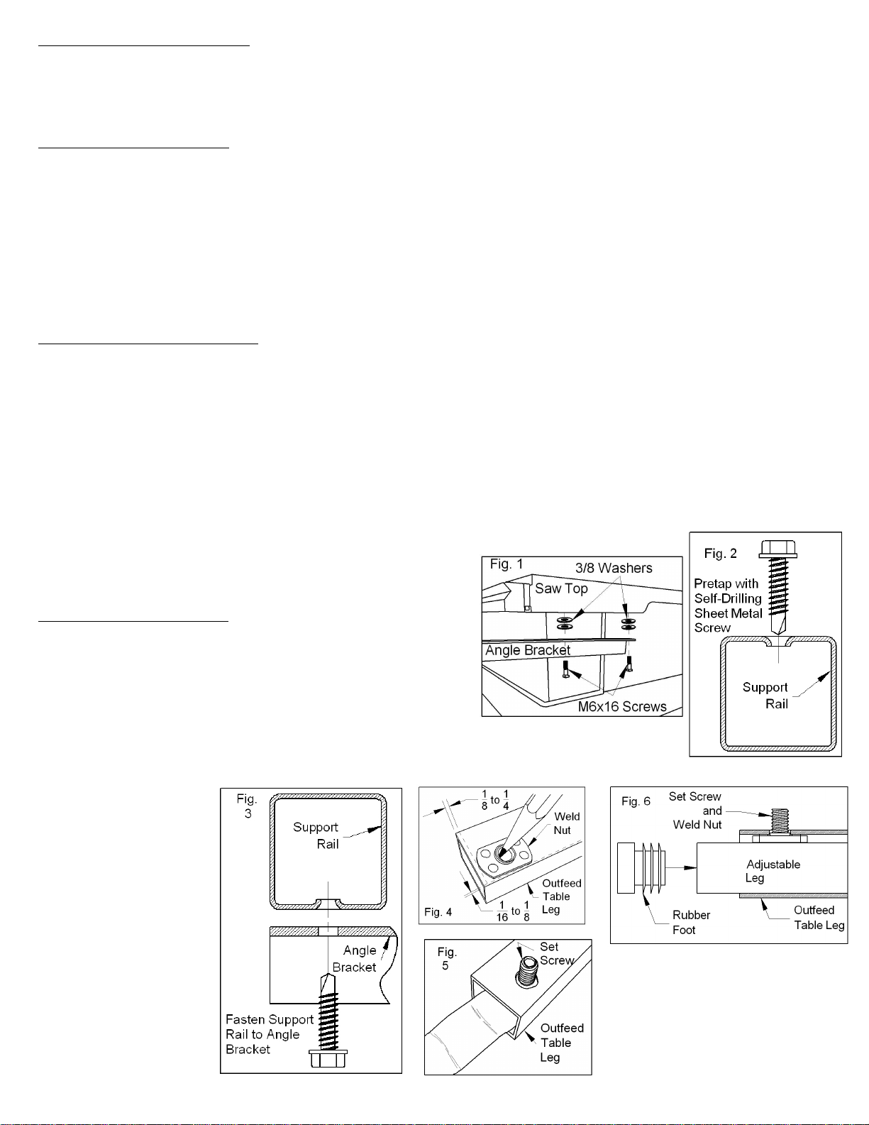
1. Attach Angle Brackets to the existing M6 tapped holes under the Saw Top using the M6x16 Screws and 5/16 Washers
supplied. See Fig. 1. Note the Angle Brackets face the same way. One bracket goes on each side of the saw. The Washers
are to space the leading edge of the Outfeed Top below the Saw Top. Fewer or more Washers can be used to raise or lower
the leading edge of the Outfeed Top as desired.
2. For easier assembly, pretap dimpled holes in Support Rail with Self Drilling Sheet Metal Screws provided. See Fig. 2.
Remove these screws and set the Support Rail on the Angle Braces attached to the Saw Top. Insert the Self Drilling Sheet
Metal Screws through the end holes in the Angle Braces and back into the Support Rail. See Fig. 3. Tighten all the screws.
3. Insert the protruding edges of the two 1½” End Caps into the ends of the Support Rail.
INSTALLING ADJUSTABLE LEGS
4. Use the Weld Nut provided for a template to locate the hole in the Outfeed Table leg. See Fig. 4. This hole can be on any
side of this leg. The outside is easier to get at for adjusting but the inside protects the set screw from damage. Another hole
can always be drilled later if the original location doesn’t work out. The Weld Nut is located against one side so it doesn’t turn
when tightening the set screw.
5. Center punch and drill 5/16 hole in both Outfeed Table legs.
6. Insert Rubber Feet into one end of each Adjustable Leg.
7. Screw the pointed end of the Set Screw into the protruding side of the Weld Nut until the point is flush with the flat side of
the Weld Nut. With the Set Screw in the Weld Nut, push the threads of the Set Screw through hole just made in the Outfeed
Table leg from the inside of the leg. See Fig. 5. While holding the Set Screw by the threads, insert
the end of an Adjustable Leg without a Rubber Foot into the
Outfeed Table leg and Tighten the Set Screw with 1/8” Allen
Wrench. Repeat for the other Outfeed Table leg. See Figure 6.
SETUP AND ADJUSTMENTS
1. Unfold saw table and place on level ground or floor surface.
Raise saw top to normal working level.
2. Set Rousseau Model 2720 Outfeed Table hooks onto 2721
Support Rail.
3. Loosen Set Screws and set back of Outfeed Table slightly above
saw top level. Tighten Set Screws.
4. Run a piece of straight test material over the saw top and onto the Outfeed Table. The test
material should clear the front edge of the Outfeed table, be supported by the center portion of the
Outfeed Table but not lift off the saw top as it reaches the back of the Outfeed Table. Add or remove
Washers and adjust the
Adjustable Legs as
needed.


