Ruff Cycles Ruffian Installation instructions

1
ORIGINAL OPERATING MANUAL

2

3
Manufacturer:
THE RUFF GmbH
Im Gewerbepark D36
93059 Regensburg
Germany
info@ru-cycles.com
www.ru-cycles.com
V1.1, March 2018
Layout, photographs and text: THE RUFF GmbH, Regensburg, Germany
Texts were provided with courtesy of HNF GmbH
The mentioned brand names are subject to copyrights and are the property of their legitimate
owners even without special indication. Any reprint or copy, even only in extracts, is only permitted
with our express written consent. Subject to misprints, errors and technical alterations. Please
note that the illustrated product may be dierent from the delivery condition of the product.

4
1.
Your Vehicle 6
1.1. Intended use 7
1.2. Vehicle overview 9
1.3. Delivery scope 10
1.4. Assembly of accessories 10
2. Commissioning 10
2.1. Handlebar alignment 11
2.2. Pedal assembly 11
2.3. Setting the saddle distance 12
2.4. Removal/Installation of the battery 13
2.5. Switching ON/OFF the drive 13
2.6. Adjusting support level 14
2.7. Switching ON/OFF the lamp 14
2.8. Initial engagement of brake discs 14
3. Before each ride 15
3.1. Check tires 15
3.2. Checking the brake system 15
3.3. Checking the chain 16
3.4. Battery: Checking the fixation and charging status 16
3.5. Checking the fork 16
3.6. Checking the screw connections 17
3.7. Checking the lights 17
4. Operating 18
4.1. NuVinci hub gear 18
4.2. Drive units 19
4.3.1. Belt Drive Units 19
4.3.2. Chain Drive Units 20
4.3. Brake system 20
4.4. Side stand 21
5. Ergonomic setting 21
5.1. Setting saddle position and inclination 21
5.2. Brake lever 22
5.2.1. Adjusting brake lever position 22
5.2.2. Brake grip angle 22
5.2.3. Adjusting brake lever distance 23
CONTENTS

5
6. Maintenance 23
6.1. Wear parts list 24
6.2. Recommended maintenance intervals 24
6.3. After an accident 25
6.4. Battery 25
6.5. Tires 26
6.6. Changing tires/tubes 26
6.6.1. Dismounting the front wheel 26
6.6.2. Dismounting the rear wheel 28
6.6.3. Changing tires/tube 29
6.6.4. Front wheel assembly 29
6.6.5. Rear wheel assembly 30
6.7. Setting the NuVINCI shifter cable play 31
6.8. Brakes 31
6.8.1. Wear of brake pads and discs 31
6.8.2. Checking the brake pads 32
6.9. Setting the headlight range 32
7. Cleaning and maintenance 32
8. Transport on/by car. 33
9. Technical data 34
9.1. Component list 34
9.2. Weights 35
9.3. Torque of screws 35
10. Liability for Material Defects 36
11. EC declaration of conformity 37
12. Disposal 38

6
Index and symbols in this User Manual
This User Manual contains important information for the enhanced safety and
prolonged service life of the Pedelec for an each time greater fun with your
Ruan.
Any neglect of the contents of this User Manual may lead to damages to the
vehicle as well as injuries.
The following symbols are used in the User Manual:
Warning!
This symbol indicates a possible danger.
Please observe the safety instructions!
Information
Here, you will find useful information on the maintenance of the
product.
Important information!
The User Manual of your Ruan is constantly checked and updated.
This instruction corresponds to our level of knowledge at the time of
publication. We recommend you to visit our website
www.ru-cycles.com,for any modifications. Here you can also
download the updated manual in PDF format.
1. YOUR VEHICLE

7
We congratulate you with the purchase of the BOSCH driving technology.
You have decided for a state-of-the-art means of transport, which allows you
brand-new mobile options. We have attached the greatest importance1to the
technical quality of the single components of your Pedelec, ensuring that you
will enjoy your Ruan for many years.
The Ruan is a bicycle with electrical power assistance for the driver. This
aid is adjusted via a controller that evaluates the data through three sensors
(speed, step rate and torque), regulating the motor according to the selected
support level. When reaching a speed of 15.53 miles/h (25 km/h), the electri-
cal motor switches o. But driving at a speed of 15.53 miles/h (25 km/h) by
oneself is also possible.
In Germany, the Pedelec is lawfully equivalent to the bicycle2. No permit or
license plate are required. The driver does not need a driver license. We do
recommend that you wear an appropriate helmet and goggles for your own
safety.
1.1. INTENDED USE
Your Ruan is intended for the transport of one person on asphalt roads and
rideable forest and land routes. The additional allowable load
(Driver + Accessory + Baggage) amounts to 120 kg.
The Ruan is not intended for:
»Racing/Competition
»Cleaning with a water jet
»Transport in the rain by a car without covering the motor and dismantling the
battery and display
»Charging the Pedelec outdoors in a wet environment
1 Pedal Electric Cycle
2 § 1 Par.3 StVG (Street trac act)
YOUR VEHICLE

8
Intended use is also limited by:
»The safety instructions in this User Manual
»The „Technical data“ chapter in this User Manual
»The national regulations for street transport (StVO)
»The national regulations for the street transport permit ordinance (StVZO)
The following user groups should not use the Pedelec:
»Persons with a limited physical, sensory or mental capacity.
»Persons who due to their body size, cannot safely drive the bicycle.
Any changes to your Ruan increasing the motor output or maximum
support speed, will endanger your driving safety and convert the
vehicle from a Pedelec into a small motorcycle. You will be exposed
to sanctions in accordance with trac, licence and safety regulation
with penal consequences!
Rotating parts such as wheels, chain ring, sprocket, pedal crank or
pedals may draw into clothing, carried objects and even body parts,
e.g. your shawl or a bag attached to the handlebar may get caught
into the spokes during driving. When you slip your feet from the
pedals, they can get caught into the spokes. This may lead to severe
accidents!
-> Always wear tight-fitting clothes.
-> Wear shoes with non-slip, flat soles.
-> Do not attach objects onto the handlebar, as they may swing into
the front wheel.
A Pedelec always accelerates faster than a bicycle. Be always aware
that other trac participants cannot always predict your acceleration
performance.
-> Exercise your new Ruan first at a quiet location, before riding in
the busy streets.
-> Exercise the brakes. Please see also chapter 4.4. „Brake system“.
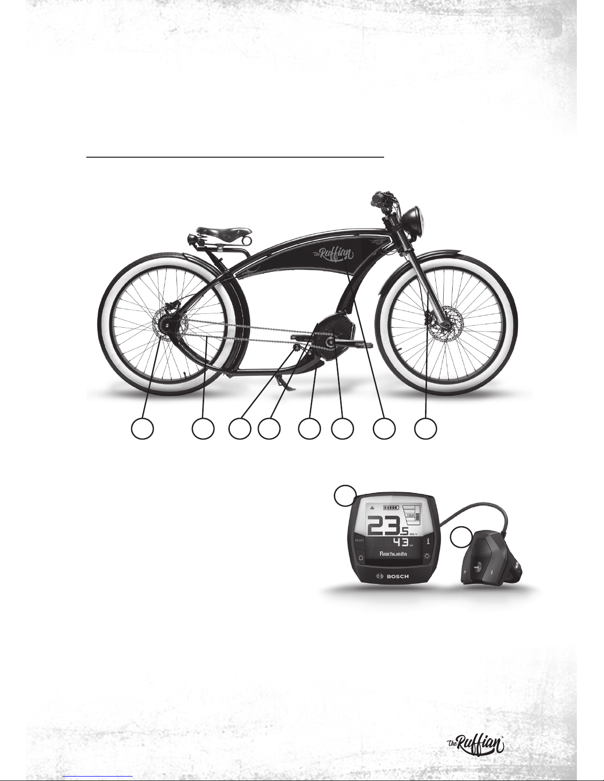
YOUR VEHICLE

9
The required active and passive illumination devices have been installed
according to the safety regulations applicable in Germany (StVZO). The tech-
nical design safety must be regularly checked and eventually be repaired by a
specialist.
1.2. VEHICLE OVERVIEW
The series number is found on the plate on the lower tube directly below the
motor. The type plate is located on top of the motor mounting holder.
Please note down the series number of the Ruan
here:__________________________________________
21 543 6 7
YOUR VEHICLE
9
1 NuVinci hub 6 Motor
2 Chain 7 Battery
3 Chain tensioner 8 Fork
4 Type plate 9 Display
5 Series number 10 Control unit
8
10

10
1.3. DELIVERY SCOPE
»Bosch charging device
»Bosch board computer
»Anti-theft safety screw on the board computer at the mounting support
»2 keys for securing the battery to the Pedelec
»2 transport fixations for the Shimano Deore brake
»or accessories for the fork
»Bosch hazardous material package for battery shipment (please store and
when appropriate, use this for the disposal or return of the defect battery)
»Delivery package (please store if you consider to cancel the purchase within
two weeks)
»User manuals of dierent component manufacturers
1.4. ASSEMBLY OF ACCESSORIES
For the assembly of the accessories, e.g. a child's seat or bicycle trailer, first
consult the accessory manufacturer or specialist dealer on their compability
with the Pedelec.
2. COMMISSIONING
This chapter explains how to prepare your Ruan for the ride.
Inflate the tires first. The air pressure volume is described in chapter 3.1.
Your Ruan is supplied as a part assembly and as a full assembly. In
the latter case, you can skip items 2.1. and 2.2.
If it is not a standard delivery, please read the following items for
„handlebar alignment“ and „Pedal assembly“.
YOUR VEHICLE

11
2.1. HANDLEBAR ALIGNMENT
The stem is a significant safety component. When tightening the bolts,
ensure that you use the torque as defined in the torque table under
9.3. Otherwise, there is a hazard of accident!
»Lift the vehicle by the front frame, so that it
no longer touches the ground. Turn the fork
leftwards and rightwards. The front wheel
must follow the movement. This simulated
steering operation should not be dicult.
»If the steering is not rotated easily, the ahead
bolt is tightened too fast (3). Loosen it by re-
leasing the 3 clamps on the top fork bridge(2).
Now you can adjust the compression of the
steering bearing with the ahead bolt. Readjust
the bolts of the fork bridge with a torque of 6-6 Nm.
»Finally, clamp the handlebar in the middle by tightening the bolts (1) at the
cross on the stem. Ensure a uniform front and rear gap between stem and
cover.
2.2. PEDAL ASSEMBLY
The right pedal has a right thread, the left pedal has a left thread
on the pedal axis. The right pedal is mounted clockwise and the left
pedal is mounted counter-clockwise. The pedals are marked with R
and L.
Pedals are important safety components. Make sure that you tighten
the pedal axis firmly, according to the manual. Otherwise, there is a
hazard of accident!
»Apply a thin layer of grease onto the thread of the pedal axis and the crank.
Next, screw the pedal by hand loosely into place. Consider the correct assem-
bly angles in order to avoid tilting.
COMMISSIONING
1
23

12
»Place the crank in a horizontal position, the
right pedal oriented towards the front wheel.
»Tighten the pedal with an SW 8 Allen key at
30 - 35 Newton meter.
2.3. SETTING THE SADDLE DISTANCE
The correct saddle distance is achieved when
you can place your football on the pedal with
your leg in extended position. The crank must
be aligned at an angle of approx. 45°.
To check the saddle distance, lean against a
wall while seated on the Pedelec, or have an-
other person hold the Pedelec.
The saddle distance is changed as follows:
»With a 13 open-end spanner, loosen both sad-
dle support clamping bolts to such a width
allowing the adjustment of the saddle.
»Retighten the bolt with the open-end wrench.
(value according to torque table in chapter
9.3.)
The saddle support clamping nut is tightened correctly, when the
saddle cannot be rotated or is slipped sideways under your body
weight.
COMMISSIONING

13
Do not pull the saddle support from
the seat tube if you want to change
the saddle height. The front part must
lie flush with the upper tube. If you
pull out the saddle support, both the
support or the upper end of the seat
tube may break. A hazard of accident
or injury exists!
2.4. REMOVAL/INSTALLATION OF THE BATTERY
1. Loosen the lower cover of the tank with a
SW3 Allen key and remove it.
2. Removing the battery:
Before removing the battery, ensure that the
system is disconnected. Turn the key in the
lock by 1/4 rotation while tilting the battery
from the upper bracket.
3. Pull the battery from the bracket.
»Installing the battery:
Install the battery with its contacts onto the
lower bracket and tilt it up to the stop into the
upper bracket, until the lock snaps in audibly.
»Remount the cover on the tank.
2.5. SWITCHING ON/OFF THE DRIVE
»Slide the supplied Intuvia board computer
onto the handlebar support.
»Press shortly the ON/OFF switch on the
Intuvia.
COMMISSIONING
1
2
3

14
COMMISSIONING
2.6. ADJUSTING SUPPORT LEVEL
For the adjustment of the support level, press
the „+“ button on the control unit until the
required support level is shown on the display.
To lower it, press the „–“ button.
2.7. SWITCHING ON/OFF THE LAMP
By pressing the light button, the LED head-
lamp and rear light are switched on and o.
Detailed information on the operation of the board computer is
found under 4.1.1. Intuvia board computer.
2.8. INITIAL ENGAGEMENT OF BRAKE DISCS
Your brake system is delivered with a weak break function, because the
surfaces of the brake discs and pads have not been engaged yet. With a new
Pedelec, and also when changing the brake discs and pads, you should en-
gage the brake discs as follows:
»Accelerate the Pedelec to approx. 15.53 miles/h (25 km/h)
»Brake the Pedelec by both brakes until standstill
(avoid to block the wheels!)
»Repeat this procedure as often as required in order to achieve an optimal
brake performance.
If you force too much the front wheel brake, a hazard of tipping over
exists. Your rear wheel might lift and have you fall over the handlebar.
-> Pull a little less at the left brake lever, or fully release the brake
lever, when you notice that the rear wheel is lifted.

15
3. BEFORE EACH RIDE
3.1. CHECK TIRES
Air pressure:
The allowed pressure range of the Cruzo Classic 76-559 is between 1 and 2.5
bar.
The following applies: The higher your weight, the higher the air pressure
to be used.
If you are not a light-weight person, set the pressure
of your rear tire at 2.5 bar.
We recommend to check the pressure every 2 - 4 weeks, since there
is an inevitable constant pressure loss of the inner tubes.
With too a low tire pressure, a puncturing hazard exists (snakebites).
This will result in a flat tire.
A tire that is damaged by tears or punctured by a sharp object may
loose its pressure. A hazard of accident exists!
-> Check that your tires are without tears or any foreign objects.
3.2. CHECKING THE BRAKE SYSTEM
»Before each ride, check your brakes at standstill. For this purpose, pull the
brake lever towards the handlebar with two fingers for a normal braking
force. The brake lever must not touch the handlebar grip
»Move the Pedelec while pulling the front and rear brakes. A too strong a play
is not allowed. If you notice any play, identify the cause. The brake calliper or
brake disc may not be tightened firmly. Tighten according to the torques in
the torque table in chapter 9.3.
»If hydraulic brake discs are used, the pressure point must be stable at the
brake lever. If the pressure point is not reached after 2/3 travel of the lever,
pull the lever several times in a row ("pumping"). Check whether the pressure
point has stiened. If so, or when the pressure point changes during the ride,
bleed the brake system by a specialist workplace.
BEFORE EACH RIDE

16
»The brake discs must be oil-free. Any oil on the brake discs is removed with
alcohol. Do not use a conventional brake disc cleaning solution!
The pressure point is the lever position of the travel at which the
brake is engaged. If brakes function smoothly - there are no air bub-
bles in the hydraulic line - the pressure point is situated at the same
lever position at each braking action.
Do not touch the brake discs with your hands. The thin grease film
on your skin is transmitted to the brake discs and aects its func-
tions.
3.3. CHECKING THE CHAIN
The chain is a product subject to wear. Please check regularly the following
items:
»Are there any foreign objects (twigs) between the chain links?
-> If so: Remove them.
»Is the chain very dirty?
-> If so: Rinse it with water or a proper cleaning solution. Then use a first
class chain lubricant.
»Lubricate the chain at regular intervals, even when it is not dirty, in order to
prevent it from significant wear.
3.4. BATTERY: CHECKING THE FIXATION AND CHARGING STATUS
Check whether the battery is secured in the lock and see whether the charg-
ing status is sucient for your planned ride.
3.5. CHECKING THE FORK
Before each ride, check the fork for:
»Breakage and deformations
»Secure fixation of the protective plate
»Firm screwing connection of the fork bridge
BEFORE EACH RIDE

17
3.6. CHECKING THE SCREW CONNECTIONS
Before each ride, check the firm screw connections for
»Quick release of the front wheel
»Screw axis of the rear wheel
Also check that the following parts do not rotate:
»Saddle
»Saddle support
»Handlebar
»Stem
Lift the vehicle slightly up and let it fall onto the ground by the tires. Check
whether you see or hear any loose parts. Identify the cause of any loose parts
and check if their torque is correct. If required, consult a specialist dealer.
3.7. CHECKING THE LIGHTS
Before each ride, check the function of the lights Ensure that the headlamp
is directed according to the lighting range defined by the national regula-
tions. See chapter 6.9.
BEFORE EACH RIDE

18
4. BEFORE EACH RIDE
4.1. NUVINCI HUB GEAR
The NuVinci gear system allows the stepless adjustment of the transmission
via a twist grip.
Changing gear during the ride
»For starting or riding up a hill, change to a
low gear ratio: Turn the Nfinity Controller
twist grip to the "Mountain" display direction
(A).
»For higher speeds, change to a higher gear
ratio: Turn the Nfinity Controller twist grip to
the "Level" display direction (B).
„Change gear“ at standstill
NuVinci Optimized hub gears do not allow the whole transmission
range for changing gear during standstill.
Normally, 50-70% of the transmission gear range is allowed during
standstill. The other transmissions can be set during the ride.
OPERATION
A
B

19
4.2. DRIVE UNITS
4.2.1. BELT DRIVE UNITS
At delivery, the belt is optimally tensioned and is not to be re-tensioned, nei-
ther after the prolonged use of the drive. When mounted correctly, a high load
can be placed on the belt in pulling direction. The carbon fibers embedded in
the belt are very flexible, but react very sensitively to
OPERATION
knicking twisting bending backwards
turning upside down binding together use as a strap
wrench
pulling up by the sprocket wheel pulling up by the lever

20
OPERATION
4.2.2. CHAIN DRIVE UNITS
At delivery, the chain is optimally tensioned and must not be re-tensioned,
neither after the prolonged use of the drive. The chain is continuously sub-
mitted to tensile load by muscle and motor power. This will extend it over
time. Optimal chain tension is maintained by the chain tensioner which also
prevents the chain from sagging. However, check the chain at a specialist
worksite at regular intervals by, since a worn-out chain will damage the chain
ring and sprocket.
4.3. BRAKE SYSTEM
Your Ruan is equipped with hydraulic brake discs for a fast and safe stop-
ping action. Use both brakes simultaneously for an optimal and safe braking.
The left brake lever has an eect on the front wheel brake, the right brake
lever has an eect on the rear wheel brake.
The brake system is provided with a fully automated lining compensation.
This osets the wear of the brake pads, while the brake pressure point re-
mains equal.
The front wheel brake has a stronger delay eect than the rear
wheel brake. Exercise the purposeful use of the front wheel brake,
so that you become familiar with its force.
If you force too much the front wheel brake, a hazard of tipping over
exists. Your rear wheel might lift and have you fall over the handlebar.
-> Pull a little less at the left brake lever, or fully release the brake
lever, when you notice that the rear wheel is lifted.
After braking, specially after long rides down the hill, the brake discs,
brake calliper and quick release and axis nuts can become very hot.
-> Do not touch the brake discs after intense braking action. You
could burn yourself.
Other manuals for Ruffian
2
Table of contents