9
STARTING UP
WARNING Pay attention to the mains voltage! The mains voltage must
correspond to the voltage indicated on the technical data identification
place (1).
DANGER Before any intervention on the electrical tool take the plug out
from the socket
BEFORE STARTING THE TOOL
Before starting-up the tool, ensure that:
- the packaging is complete and does not show signs of having been damaged
during storage or transport;
- the tool is complete; check that the number and type of components comply
with that reported in this instruction booklet;
- the power supply and socket outlet can support the load reported in the table
and that indicated on the tool identification plate reproduced;
- the power supply cable and plug are in perfect condition;
- the ON/OFF (2) switch works properly though with the power supply
disconnected;
- all the parts of the tool have been assembled in the proper manner and that
there are no signs of damage;
- the ventilation slots (8) are not obstructed;
- the tool must be connected to a suitable and efficient aspiration device.
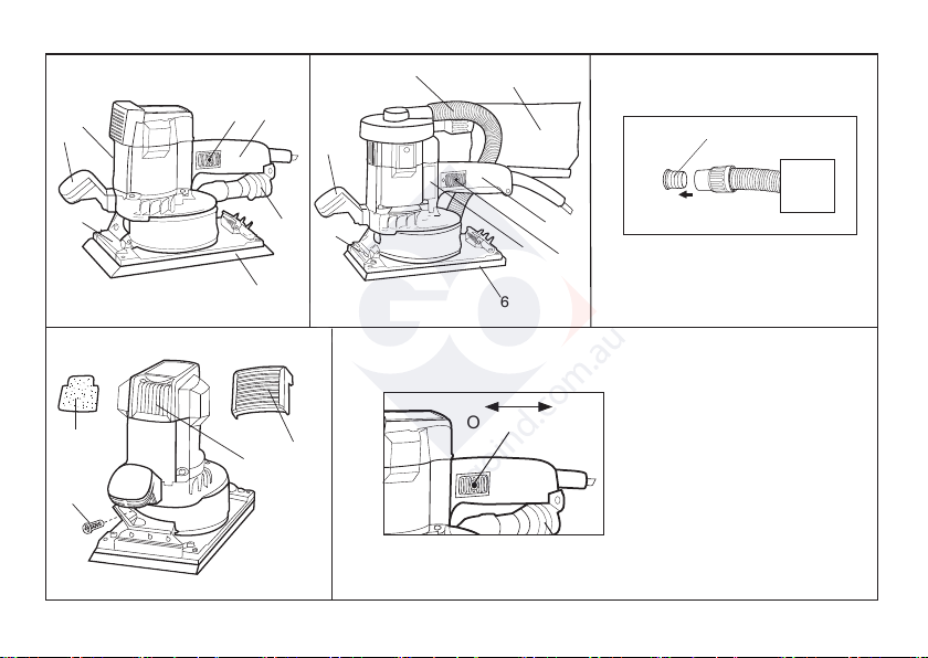
ASSEMBLY/REPLACEMENT OF THE ABRASIVE PAPER SHEET
ASSEMBLY:
ABRASIVE VELCRO PAPER
- Press the velcro backed abrasive paper in position, ensuring that the holes in
the paper coincide with the suction holes in the prefored rubber plate (6);
- make sure that there is no dust or other matter on the prefored rubber plate (6).
ABRASIVE PAPER
- insert the abrasive paper clamping lever (7) by pressing the lever release;
- repeat this operation on the opposite side of the plate, keeping the abrasive
paper taut and checking that the edges are parallel with the edges of the
prefored rubber plate (6) before releasing the paper clamping lever (7);
Sound pressure level / Sound power level 3 axis vibration level
LPA LWA Uncertainty ah Uncertainty
dB(A) m/s2
SL42AES 86 97 3 5,75 1,5
INFORMATOIN NOISE / MEAN ACCELERATION VALUE
The tools are suppressed in accordance for the prevention and elimination of radio
disturbances measured in accordance with standard: EN 62841
DANGER The indicate measurements refer to new power tools.
Daily usa causes the noise and vibration values to change.
Displayed emission values are comparative and are to be employed for
a provisional assessment of the operator’s risk exposure during the work period.
Appropriate evaluation of work period must also include tool’s idle and stop
periods. These emission values represent the tool’s main applications.
If the tool is used for other applications, with other accessories, or if it does not
undergo regular maintenance, emission values can significantly increase
during operations.
Use hearing protection!
PARTS OF THE TOOL
1 - Technical data identification label
2 - ON/OFF switch
3 - Speed control
4 - Dust extraction flow control
5 - Auxiliary handle
6 - Rubber drilled velcroed plate,
7 - Paper clamping lever
8 - Motor ventilation slots
9 - 29 mm Ø suction port
10 - Heat protection
11 - Heat protection fixing screws
9
STARTING UP
WARNING Pay attention to the mains voltage! The mains voltage must
correspond to the voltage indicated on the technical data identification
place (1).
DANGER Before any intervention on the electrical tool take the plug out
from the socket
BEFORE STARTING THE TOOL
Before starting-up the tool, ensure that:
- the packaging is complete and does not show signs of having been damaged
during storage or transport;
- the tool is complete; check that the number and type of components comply
with that reported in this instruction booklet;
- the power supply and socket outlet can support the load reported in the table
and that indicated on the tool identification plate reproduced;
- the power supply cable and plug are in perfect condition;
- the ON/OFF (2) switch works properly though with the power supply
disconnected;
- all the parts of the tool have been assembled in the proper manner and that
there are no signs of damage;
- the ventilation slots (8) are not obstructed;
- the tool must be connected to a suitable and efficient aspiration device.
ASSEMBLY/REPLACEMENT OF THE ABRASIVE PAPER SHEET
ASSEMBLY:
ABRASIVE VELCRO PAPER
- Press the velcro backed abrasive paper in position, ensuring that the holes in
the paper coincide with the suction holes in the prefored rubber plate (6);
- make sure that there is no dust or other matter on the prefored rubber plate (6).
ABRASIVE PAPER
- insert the abrasive paper clamping lever (7) by pressing the lever release;
- repeat this operation on the opposite side of the plate, keeping the abrasive
paper taut and checking that the edges are parallel with the edges of the
prefored rubber plate (6) before releasing the paper clamping lever (7);
Sound pressure level / Sound power level 3 axis vibration level
LPA LWA Uncertainty ah Uncertainty
dB(A) m/s2
SL42AES 86 97 3 5,75 1,5
INFORMATOIN NOISE / MEAN ACCELERATION VALUE
The tools are suppressed in accordance for the prevention and elimination of radio
disturbances measured in accordance with standard: EN 62841
DANGER The indicate measurements refer to new power tools.
Daily usa causes the noise and vibration values to change.
Displayed emission values are comparative and are to be employed for
a provisional assessment of the operator’s risk exposure during the work period.
Appropriate evaluation of work period must also include tool’s idle and stop
periods. These emission values represent the tool’s main applications.
If the tool is used for other applications, with other accessories, or if it does not
undergo regular maintenance, emission values can significantly increase
during operations.
Use hearing protection!
PARTS OF THE TOOL
1 - Technical data identification label
2 - ON/OFF switch
3 - Speed control
4 - Dust extraction flow control
5 - Auxiliary handle
6 - Rubber drilled velcroed plate,
7 - Paper clamping lever
8 - Motor ventilation slots
9 - 29 mm Ø suction port
10 - Heat protection
11 - Heat protection fixing screws
Sound pressure level Uncertainty Sound power level Vibration level [m/s2]
[dB(A)] [dB(A)] [dB(A)] 3 axis Uncertainty
LpA K LwA ahK
SSPF 84 3 95 3.80 1,5
SSCA 84 3 95 3.80 1.0
1 - Étiquette d’identification
2 - Interrupteur de mise en marche - arrêt
3 - Poignée
4 - Poignée auxiliaire
5 - Vis de fixation poignée auxiliaire
6 - Plaque caoutchou perforée a velcro, plaque caoutchou perforée,
plaque caoutchou standard (selon le modèle)
7 - Levier de blocage du papier
8 - Outil perforateur de papier abrasif (optional)
9 - Grille porte-filtre (SSPF - SSCA)
10 - Filter anti-poussière (SSPF - SSCA)
11 - Fentes pour ventilation moteur
12 - Bouche d’aspiration Ø 29 mm
13 - Tuyau de raccord plaque - turbine d’aspiration (SSCA)
14 - Sac à poussière (SSCA )
REPLACEMENT:
ABRASIVE VELCRO PAPER
- Used abrasive paper can be removed by simply tearing them off;
- new velcro abrasive paper are mounted (see “ASSEMBLY”)
ABRASIVE PAPER
- Lift the paper clamping lever (7) by pressing the release device and remove
the used abrasive paper;
- apply the new abrasive paper following the instructions in the chapter on
“INSERTING THE ABRASIVE PAPER”.
Start the tool and check that there are no unusual vibration, no dismatching
movement of the abrasive disc. Otherwise switch-off the tool immediately and
eliminate the cause.
STARTING AND STOPPING
- Starting: push the slide of the ON/OFF (2) forward; if the tool is to be locked in
the ON position, apply pressure to the front part of the slide switch at the same
time.
- Stopping: release the slide ON/OFF (2).
If locked, press the ON/OFF switch in the lower partdownwards and release it
in the OFF position.
WARNING: after an interruption of the electrical energy, if the
ON/OFF switch is inserted, it is necessary to release the switch
(see Stopped).
ELECTRONIC RPM REGULATION
The rpm can be adjusted by rotating the wheel speed adjustment wheel (3)
located on the rear of the tool. The choice of speed depends on the
characteristics of the abrasive paper disc and the material to be worked.
ADJUSTING THE DUST EXTRACTION FLOW
The extraction flow can be adjusted by rotating the control flow adjustment
control (4).
ACCESSORIES
- Sheets of abrasive paper with suction holes.
- Sheets of abrasive paper with suction holes 400x70 mm.
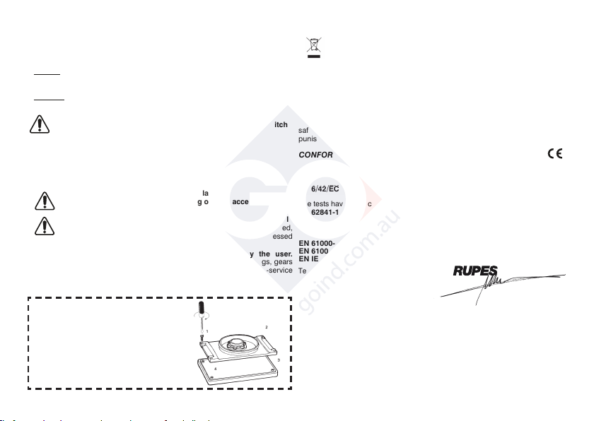
MAINTENANCE
Immediately replace the damaged rub plate.
Optimal results are achieved only using original accessories.
All maintenance operations are carried out with the power supply
disconnected. At the end of each work session, or when required,
remove any dust from the body of the tool using a jet of compressed
air, paying particular attention to the motor ventilation slots.
No other maintenance operations must be undertaken by the user.
Maintenance and cleaning of the inner parts, like brushes, ball bearings, gears
etc. or others, must be carried out only by an authorized customer-service
workshop or on www.rupes.com.
Use only the original RUPES parts or accessories.
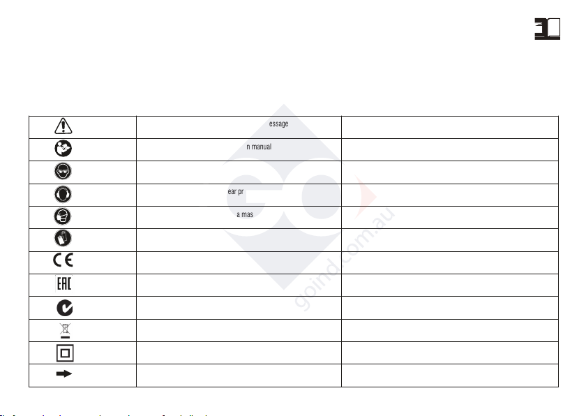
DISPOSAL (WEEE DIRECTIVE)
For EU countries only: According to the European Directive on Waste
from electrical and electronic equipment and its implementation in
conformity with national standards, exhausted electrical equipment
EN 50581: 2012
Vermezzo (MI), 01/01/2015
IL PRESIDENTE
G. Valentini
S.p.A
must be collected separately, in order to be recycled in an environmentally friendly
way. The product, when it reaches the end of its life, must not be dispersed in the
environment or thrown away as household waste. It must be disposed at
authorized recycling centres (contact your local authorities to know where to
dispose of the product according to the law). The correct disposal of the product
contributes to the health and preservation of the environment.
Illegal disposal of the product will entail penalties against the offenders.
Disposing of the product correctly contributes to protecting human health and
safeguarding the environment. Any illegitimate disposal of the product will be
punishable by law .
CONFORMITY DECLARATION
We declare on our responsability that the hand-held motor operated tool, which
is mentioned in the present operating manual, is in comformity with the Essential
Requirements of Safety of the following Directives:
2006/42/EU; 2004/108/EU; 2011/65/EU.
The tests have been carried out in accordance with following Standards:
EN 60745-1: 2009 + A11: 2010
EN 60745-2-4:2009+ A11:2011.
EN 55014-1: 2006 + A1: 2009 + A2: 2011
EN 55014-2: 1997 + A1: 2001 + A2: 2008
EN 61000-3-2: 2006 + A1: 2009 + A2: 2009
EN 61000-3-3: 2008
Technical file at:
RUPES S.p.A.
Via Marconi, 3A
20080 VERMEZZO (Mi) - Italy
TYPE
INSULATION CLASS
ABSORBET POWER W
ELECTRONIC OVERLOAD
ELECTRONIC SPEED CONTROL
n0 Empty RPM /min
Ø ORBITAL mm
VELCROED DRILLED RUBBER PLAT
PLATE DIMENSION mm
VACUUM SISTEM (*)
DUST EXTRACTION FLOW CONTROL
WEIGHT kg according to EPTA-Procedure 01/2003
SL42AES
/ II
550
•
•
3.000÷7.000
4,8
•
400 x 70
CENTRALIZED
YES
2,9
8
TECHNICAL DATA
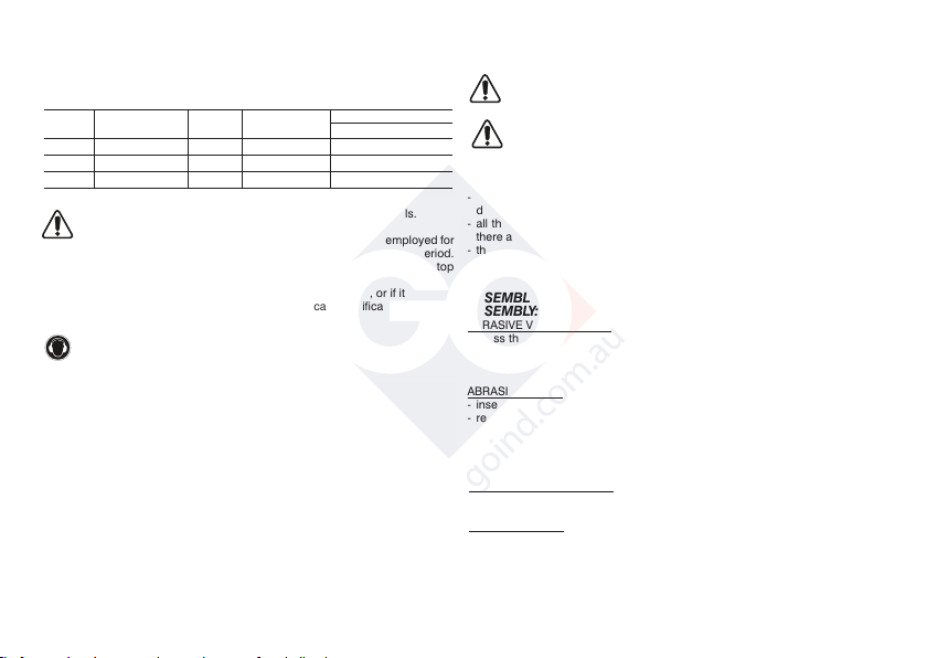
GENERAL WARNINGS
All instructions concerning safety and the prevention of industrial accidents
can be found in file SAFETY INSTRUCTIONS, that forms integral part of this
documentation. This INSTRUCTION MANUAL only contains additional
information that specifically explain how to use the machine.
SPECIFIC USE
This electrical tool is designed to operate as a sander, suitable for dry
sanding of wood, plastic, metal, plaster and painted surfaces. Read all
safety warnings, instructions, illustrations and specifications supplied with
this tool. Failure to respect all instructions indicated below can cause an
electric shock, fire and/or a serious accident. Grinding, polishing, metal
brushing or cutting operations are not recommended with this tool.
Failure to follow all the instructions provided below may result in serious injuries.
Do not use accessories that are not specifically designed for the intended
use of the tool or that have not been recommended by the manufacturer.
The fact that an accessory can be fixed to the tool does not imply that it can be
used safely.
The rated speed of accessories must be at least equivalent to the maximum
speed of the tool. If operated at a greater speed than the rated one,
accessories may break and cause the ejection of chips.
The external diameter and thickness of accessories must be appropriate to
guarantee the protection and safety of the tool. Accessories with incorrect
dimensions cannot be adequately protected or controlled.
The conformation of the accessories must be correctly adapted to the
spindle of the tool. The accessories equipped with holes of the shaft that
do not correspond to the assembly components on the tool, will not remain
in balance, they will vibrate excessively and can cause a loss of control.
Do not use a damaged accessory. If the tool or accessory has suffered a fall,
examine any damages or install an accessory that is no damaged. After
examining and installing an accessory, all persons present, must keep a safe
distance from the rotating accessory and operate the tool at maximum empty
speed for one minute. Damaged accessories generally break during this test
period.
Use the electric tool only for dry sanding. The use of water or other liquid
coolants can cause electrocution or an electric shock.
Do not operate the electrical tool in the proximity of flammable material. The
sparks generated by sanding metal material can ignite these materials.
Avoid overheating the material being processed and in sanding.
Before taking a break, always empty the container of dust. The abrasion dust
in the dust collection bag or in the dust intake filter can set on fire under
unfavourable conditions, such as a trail of sparks produced while sanding the
metal.
Connect the tool to a device suitable dust extraction. To protect the health
wear masks
Use clamps to secure the work piece. Under no circumstances should you
hold the work piece with one hand and the electrical tool with the other hand,
while it is being used. By securing the work piece with clamps, you can have
both hands free to better operate the electrical tool.
The values shown are based on a nominal voltage of 230V/50Hz. In the case of voltages and frequencies of different power values may vary.
Refer to the label technical specifications to the nominal values of the tool.
(*) The tool must be connected to a suitable dust extraction system (not supplied).