Rupes RA150A Wiring diagram

RA150A
Levigatrice rotorbitale pneumatica con aspirazione
Random-orbital pneumatic sander with dust extraction
Ponceuse rotorbitale pneumatique avec aspiration
Pneumatische Exzenterschleifer mit Staubabsaugung
Lijadora rotórbitale neumática con aspiración
Pneumatisch roterend excentrische schuurmachine
met stofafzuiging
Пневматические вращательно-орбитальные шлифовальный
машины с пылеудалением
ISTRUZIONI ORIGINALI PER L'USO
TRANSLATION OF ORIGINAL OPERATING INSTRUCTIONS
CONVERSION DES INSTRUCTIONS DE FONCTIONNEMENT ORIGINAL
ÜBERSETZUNG DES URSPRÜNGLICHEN BEDIENUNGSANLEITUNG
TRADUCCIÓN DE MANUAL DE INSTRUCCIONES ORIGINAL
VERTALING VAN ORIGINELE GEBRUIKSAANWIJZING
ПЕРЕВОД ИНСТРУКЦИИ ПО ЭКСПЛУАТАЦИИ
Via Marconi, 3A - 20080 VERMEZZO (Mi) - ItalyTel. 02/946941 - Fax 02/94941040
9.2562 RA150A_giu2015:libretto RA90A-RA125A-RA150A OK.qxd 12/06/2015 8.52 Pagina 1

MAX OFF
RA150A
6
VACUUM
SYSTEM
1
4
8
9
10
7
3
6
5
2
9.2562 RA150A_giu2015:libretto RA90A-RA125A-RA150A OK.qxd 12/06/2015 8.52 Pagina 2

TECHNICAL DATA
TYPE RA150A
WORKING PRESSURE bar/PSI 6.2/90
AIR CONSUMPTION l/min 380
SPEED CONTROL YES
RPM 0 ÷ 11.000
Ø ORBITAL DIAMETER mm 5
Ø DISC PAD DIAMETER mm 150
EXTRACTION SYSTEM CENTRALIZED
WEIGHT Kg 0,950
ENGLISH TRANSLATION OF ORIGINAL OPERATING INSTRUCTION 8
Warning symbol/ Warning messageI SO7010 - W001
Read instruction manual ISO7010 - M002
Wear eye protection ISO7010 - M004
Wear ear protection ISO7010 - M003
Wear a mask ISO7010 - M016
Wear a gloves ISO7010 - M009
CE compliant
EurAsian Mark
Arrow Act in the direction indicated by the arrow direction
SIMBOLS
Some of the following symbols may be used on your tool. Please study them and learn their meaning. Proper interpretation of these
symbol will allow you to operatethe tool better and safer.
9.2562 RA150A_giu2015:libretto RA90A-RA125A-RA150A OK.qxd 12/06/2015 8.53 Pagina 8

9
GENERAL WARNINGS
The tool must be connected to a suitable dust extraction system
(not supplied).
SAFETY AND ACCIDENT PREVENTION INSTRUCTIONS
The safety and accident prevention instructions are reported in the
“SAFETY INSTRUCTION” booklet which forms an integral part of
these documents; the operating instructions indicate the
additional information required specifically for use of the tool.
Never use the tools without the safety guards.
Any operations carried out on the tool must be effected with the
tool disconnected.
Before starting the tool, ensure that it is held tightly and not in
contact with the work surface.
The electric tool must be connect to a suitable dust extraction unit
and applicable safety regulations must be observed if dusts
dangerous to health are likely to occur during sanding.
Due to risks that may arise during sanding, we recommend the
constant use of P.S.D. (personal safety devices such as gloves,
headphones, goggles, face masks, etc.) according to laws in
force to prevent or reduce accident probability.
Warning! Carry out the lubrication process outlined in the
maintenance paragraph. The appliance continues to work for a
few seconds after it has been switched off.
CORRECT USAGE
The sanders are designed for sanding wood, plastic, composite
materials, paint/varnish, filling material and similar materials.
Metal and materials with an asbestos content must not be
processed with these tools.
The tools must not be damp nor operated in a damp environment
for electrical safety reasons.
The tools may only be used for dry sanding.
Make sure the work piece is sufficiently fastened.
In the event of improper use, the user is fully liable for any
damages or accidents.
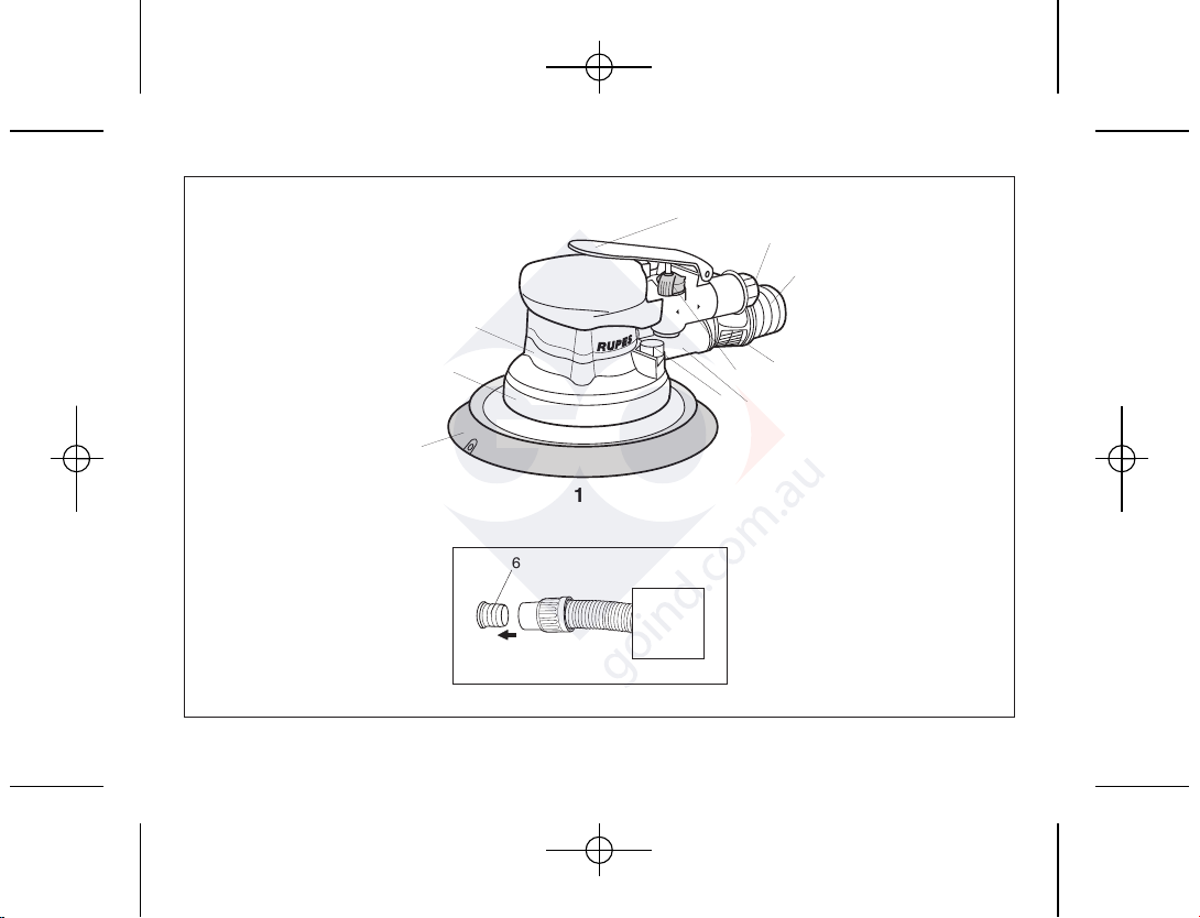
PARTS OF THE TOOL
1 - Identification plate
2 - Compressed air on/off lever
3 - Speed control
4 - Tool body
5 - Compressed air connection
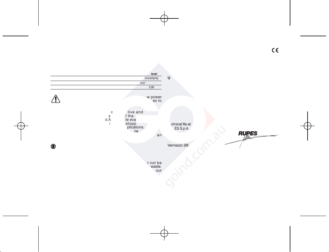
6 - 29 mm. int. Ø suction pipe connection
7 - Dust extraction flow control
8 - Suction cowling
9 - Backing pad
10 - Backing pad release button
STARTING UP
Before starting-up the tool, ensure that:
- the packaging is complete and does not show signs of having
been damaged during storage or transport;
- the tool is complete; check that the number and type of components
comply with that reported in this instruction booklet;
- the available compressed air production and distribution plant is
capable of satisfying the requirements reported on the tool’s
identification plate.
ASSEMBLING THE TOOL
Assemble the compressed air connection (not supplied) by
screwing it into its seating (5).
COMPRESSED AIR CONNECTION
The tool is supplied without the compressed air connection; the
user can use either a quick release coupling or hose type
connection according to his needs, purke they have an hole of air
passing mm. 8. In the latter case the air line must be fixed to the
nozzle by a hose clip.
9.2562 RA150A_giu2015:libretto RA90A-RA125A-RA150A OK.qxd 12/06/2015 8.53 Pagina 9

10
In the latter case the air line must be fixed to the nozzle by a hose
clip.
REMOVING AND MOUNTING THE BACKING PAD
1.Press the lock button (10);
2.screw the backing pad on by hand while keeping the release
button pressed;
3.reverse the procedure when removing the backing pad.
FITTING ABRASIVE PAPER DISCS
Press the abrasive disc into the pad ensuring that the holes in the
abrasive paper coincide with extraction holes in the disc pad.
BEFORE STARTING THE TOOL
Ensure that:
- the speed control (3) is in MAX position;
- the compressed air feed line and connection are in perfect
working order;
- the start lever is working properly. This must be done with the air
supply switched off;
- all the components of the tool are mounted correctly and do not
show any signs of damage;
- the tool must be connected to a suitable and efficient aspiration
device.
STARTING AND STOPPING
- Starting: push the control lever (2) forward towards the body of
the tool and keep it pressed.
- Stopping: release the control lever.
TEST RUN
Start the tool and check that there are no unusual vibration, no
dismatching of the abrasive paper disc.
Otherwise switch-off the tool immediately and eliminate the
cause.
SELECTING THE RPM
The number of revolutions can be adjusted by using the speed
control (3) from MAX to OFF. The choice of speed depends on the
characteristics of the abrasive paper disc and the material to be
worked.
ADJUSTING THE DUST EXTRACTION FLOW
The extraction flow can be adjusted by rotating the control (7);
REPLACING THE ABRASIVE PAPER DISCS
- Used discs can be removed by simply tearing them off;
- new velcro discs are mounted by simply pressing them into the
backing pad, making sure that the holes cut in the disc coincide
with those in the backing pad.
USABLE DISCS
velcro backed abrasive paper discs Ø 150 mm with dust extraction
holes.
MAINTENANCE
All maintenance operations are carried out with the tool
disconnected from the compressed air supply.
At the end of each work session, or when required, remove any
dust from the body of the tool using a jet of compressed air.
Lubricate the machine regularly (every 50 hours of operation) by
inserting 2/3 drops of specific oil into the compressed air
connection, keeping the device in a vertical position, with the
connection facing upwards. After this operation, connect the
machine to the power supply and set it in motion for a few
seconds.Lubricate the machine as described above before storing
it for long periods of inactivity.All damages deriving from incorrect
or inadequate lubrication are excluded from the warranty.
No other maintenance operations must be undertaken by the user.
Maintenance and cleaning of the inner parts, must be carried out
only by an authorized customer-service workshop.
9.2562 RA150A_giu2015:libretto RA90A-RA125A-RA150A OK.qxd 12/06/2015 8.53 Pagina 10

11
INFORMATOIN NOISE / MEAN ACCELERATION VALUE
The tools are suppressed in accordance for the prevention and
elimination of radiodisturbances measured in accordance with
standard:
UNI EN ISO 15744 - EN ISO 28927.
Sound pressure level / Sound power level 3 axis vibration level
LPA LWA Uncertainty ahUncertainty
dB(A) m/s
2
RA150A 77 88 3 2,50 0,80
DANGER The indicate measurements refer to new power
tools.Daily usa causes the noise and vibration values to
change.
Displayed emission values are comparative and are to be
employed fora provisional assessment of the operator’s risk
exposure during the work period.Appropriate evaluation of work
period must also include tool’s idle and stopperiods. These
emission values represent the tool’s main applications. If the tool
is used for other applications, with other accessories, or if it does
notundergo regular maintenance, emission values can
significantly increaseduring operations.
Use hearing protection!
DISPOSAL
The product, when it reaches the end of its life, must not be
dispersed in theenvironment or thrown away as household waste.
It must be disposed atauthorized recycling centres (contact your
local authorities to know where todispose of the product
according to the law). The correct disposal of the
productcontributes to the health and preservation of the
environment.Illegal disposal of the product will entail penalties
against the offenders.Disposing of the product correctly
contributes to protecting human health andsafeguarding the
environment. Any illegitimate disposal of the product will
bepunishable by law.
CONFORMITY DECLARATION
We declare on our responsibility that the hand-held power tool, which is
mentioned in the present operating manual, is in conformity with the
Essential Requirements of Safety of the following Directive:
2006/42/CE Macchine
he tests have been carried out in accordance with following Standards:
UNI EN ISO 11148-8 - UNI EN ISO 15744 - UNI EN ISO 28927
Technical file at:
RUPES S.p.A.
Via Marconi, 3A
20080 VERMEZZO (Mi) - Italy
Vermezzo (MI), 03/02/2014
IL PRESIDENTE
G. Valentini
S.p.A
9.2562 RA150A_giu2015:libretto RA90A-RA125A-RA150A OK.qxd 12/06/2015 8.53 Pagina 11

RUPES S.p.A.
Via Marconi, 3A
20080 VERMEZZO (Mi) - Italy
Tel. 02/946941
Fax 02/94941040
Uff. Vendite e assistenza clienti
Tel. 02/94694312
e-mail: [email protected]
web: http://www.rupes.com
COD. ART. 9.2562 - GIUGNO 2015
9.2562 RA150A_giu2015:libretto RA90A-RA125A-RA150A OK.qxd 12/06/2015 8.54 Pagina 32
Other manuals for RA150A
1
Table of contents
Other Rupes Sander manuals