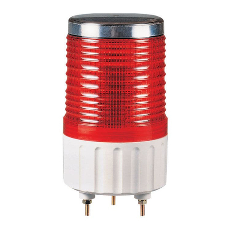
RusAutomation S100D Series User manual

1
5020
54
105
HORN
5030
Signal/ Warning Light and Alarm Sounder Combinations
S100D series
S100D - WA - 220 - R
[Model number] [Sound] [Voltage] [Color]
| | | |
• S100DLR
• S100DL
• S100DS
• S100D
• WS- Warning sounds
• WM- Melodies
• WA- Alarms
• WV- Customizable sounds
• 12-DC12V
• 24-DC24V
• 110- AC110V
• 220- AC220V
R-Red
A-Amber
G-Green
B-Blue
Ordering Specications
Thank you for purchasing Qlight’s products. Please read this user
manual carefully prior to installation and operation to ensure safe and correct use.
Precautions for Safety
Failure to follow the instructions below may cause a loss of life or serious physical injury.
1. Please remove any objects that can interrupt ventilation around the product.
2. Please turn o the power of the product immediately if it fails to operate properly.
3. Carefully wire the product according to each product’s specication.
4. Please be careful in preventing chemicals such as thinner, benzene, etc. in contact with the surface of the product.
5. Do not apply excessive force/impact to the product.
6. Failure to follow any of the instructions above may cause malfunction or damage to the product, re, and electric shock.
Precautions for Correct Use
Failure to follow the proper instructions may cause damage to property, the product, and or malfunction of the
product that would void the warranty.
1. During wiring or maintenance, please completely turn o the power of the product. (Failure to follow this may lead to an electric shock.)
2. Do not install the product in locations that subjects it to excessive dust or water other than the conditions designated by the IP protection
ratings indicated for each product. (Failure to follow these instructions may cause a re to the product, electric shock, physical injury,
malfunction or damage to the product.)
3. Do not alter or repair this product. If maintenance or repair service is required, please contact your local Qlight contact point. (Failure to
follow these instructions may lead to re, electric shock, or product damage.)
4. Please apply the correct voltage to the product. (Failure to follow these instructions may lead to re, electric shock, or product damage.)
5. When the product is applied to a condition that may impact lives or property, please make sure to have a double safety device. (Failure to
follow this may cause damage to property, re, electric shock and loss of life.)

2
Ø119
94112
226
15
Ø10
CABLE ENTRY
Ø101
360°/3-M5 BOLT
PCD70
S100D/ S100DL/ S100DLR/ S100DS
• Protection rating :IP54
• Ambient operating temperature : -20°C to +50°C (S100D, S100DLR)
-30°C to +50°C (S100DL, S100DS)
Model number Voltage Current
Bulb specications
Sound pattern and volume
Certicates
Weight Color
Volts/Watts
Conguration
Part#
S100D
DC12V 1.266A
12V10W T16x35 15S 9
• WS- 5
Warning Sounds
: 105dB
• WM- 5 Melodies : 105B
• WA- 5 Alarms : 103dB
• WV- 5
Customizable sounds
: 95dB
0.96Kg
R-Red
A-Amber
G-Green
B-Blue
DC24V 0.766A
24V10W T16x35 15S 10
AC110V 0.187A
12V10W T16x35 15S 9
1.38Kg
AC220V 0.094A
12V10W T16x35 15S 9
Model number Voltage Current Sound pattern and volume
Certicates
Weight Color
S100DL
DC12V~24V Max. 0.410A
• WS- 5
Warning Sounds
: Max. 105dB
• WM- 5 Melodies : Max.105B
• WA- 5 Alarms : Max.103dB
• WV- 5
Customizable sounds
: Max.95dB
0.89Kg
R-Red
A-Amber
G-Green
B-Blue
AC110V 0.115A 1.27Kg
AC220V 0.060A
S100DLR
DC12V 0.483A 0.95Kg
DC24V 0.327A
AC110V 0.120A 1.16Kg
AC220V 0.060A
S100DS
DC12V~24V Max. 1.330A 0.76Kg
AC110V 0.230A 1.21Kg
AC220V 0.155A
※CE compliant : DC24V
Dimensions
(Units : mm)
Specications

3
Parts Denition/ Installation
•First, remove the ange nuts from bolts and place the product through the mounting surface holes.
•Fasten the ange nuts on the opposite side of the mounting surface until the product is tightened securely.
S100DLS100D S100DLR S100DS
Flange nut
Lens(AS)
LED Unit LED Unit
Reector
(Heat resistant ABS)
Light bulb
Cover connector
(ABS)
Rubber spacer
Resonator
(Material:ABS)
Xenon bulb
• The volume output of this product
is adjustable.
• Turn the volume dial clockwise to
increase the volume, and turn
counter clockwise to decrease the
volume.
• There will be no sound when the
dial is put at MIN.
Volume Dial
VOL.
MAX. MIN.
Volume Adjustment
Wiring Instructions
Sound Tone Combination of Standard Product
•External power line - UL1015 AWG18(0.75sq) x 2C 400mm
•External signal line - UL1007 AWG22(0.3sq) 400mm
S100D/ S100DL/ S100DLR/ S100DS-DC/AC
S100DL-DC/AC
EXTERNAL CONTACT
Fuse
Common
POWER
Fuse POWER
EXTERNAL TRANSISTOR-NPN
Common
Category Sound pattern Channel Sound tone Volume
(Max.)
WS
5 Warning
sounds
Ch1
Fire
105dB
Ch2
Emergency
Ch3
Ambulance
Ch4
Machinery Fault
Ch5
High Expansion
WM
5 Melodies
Ch1
Sweet Home
105dB
Ch2
For Elise
Ch3
Cuckoo's Waltz
Ch4
Piano Sonata
Ch5
Turkish March
WA
5 Alarms
Ch1
Beep Intermittent
103dB
Ch2
Door Chime
Ch3
Phone Ring
Ch4
PI.PI.PI Short
Ch5
Tripping Beat
WV
5 Customizable
sounds
Ch1-
Ch5
Available upon
request(customized
voice type)
95dB
Ch 1
Ch 2
Ch 3
Ch 4
Ch 5
Ch 1
Ch 2
Ch 3
Ch 4
Ch 5
Red(R)
Amber(A)
Green(G)
Blue(B)
White(W)
White(W)
Black(BK)
Black(BK)
Red(R)
Amber(A)
Green(G)
Blue(B)
White(W)
White(W)
Black(BK)
Black(BK)

4
360°/3-
Ø6
HOLES
Min. Ø5
CABLE ENTRY
PCD70
①
②
▶
LF : Flashing
▶
L : Steady
Installation Environment and Protection Rating
• This product is designed for use with protection rating of IP54.
• If the product is installed in locations that subject it to excessive dust or water other than the designated IP protection rating
indicated(IP54), it may cause malfunction or damage to the product.
• In case of outdoor applications, install the product in the upright position. Do not install the product horizontal or upside-
down positions where water can potentially penetrate into the product and impact it’s operation.
•For further information, please visit our website (www.qlight.com).
• Machine holes on the mounting surface referring to the
diagram below.
• Please refer to the chart below to use light function
selection switch located inside the product.
• Default function is set at steady LED. Select the desired
function for your application during installation.
Assemble bulb
Disassemble bulb
Light Function Selection/ Mounting Hole Specications
Light bulb/ Xenon Bulb Replacement lnstructions
■
Light Function Selection(100DL only)
■
Bulb Replacement Instructions(S100D model only)
■
Mounting Hole Specications
■
Xenon Bulb Replacement instructions(S100DS only)
①
②
•Please wait at least 30 mimutes after turning o the power before
replacing the xenon bulb.
•Please pull out the entire xenon bulb structure ① to disassemble.
• For xenon bulb assembly, please ensure the connector portion of
the xenon bulb structure matches the pin location②.
Disassemble
xenon bulb Assemble
xenon bulb
• Please wait at least 1 minute after turning o the power
before replacing the bulb.
• In order to dissemble the bulb, please push down the bulb(①)
lightly and screw it counterclockwise.
• In order to put the bulb in to the unit, please place the bulb(①)
in the socket(②) and screw it clockwise while lightly pushing
down the bulb.
ООО “РусАвтоматизация”
454010 г. Челябинск, ул. Гагарина 5, оф. 507
тел. 8-800-775-09-57 (звонок бесплатный), +7(351)799-54-26, тел./факс +7(351)211-64-57
This manual suits for next models
4
Table of contents
Other RusAutomation Security System manuals