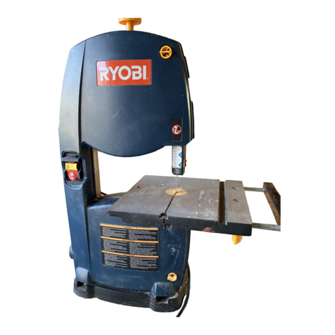
Ryobi RBS904 User manual

FRONT PAGE
RBS904
EN
FR
DE
ES
IT
NL
PT
DA
SV
FI
NO
RU
PL
CS
HU
RO
LV
LT
ET
HR
SL
SK
BG
UK
TR
EL

Fig. 1
10
12
9
15
17
13
14
8
11
24
OFF
16
23
5
3
2
2
6
18
22
20
1
19
21
4
7

Fig. 2
Fig. 3 Fig. 5
Fig. 4
7
12
31
28
29
30
19
39
31
37
35
38
33
36
25 26 27
32
33
34
40
32
33
34
19

Fig. 6
Fig. 8 Fig. 9
Fig. 7
35
36
33
31
12
10
10
41
31
12
42
14
13
12
9
27
13
37
43
29

Fig. 10
Fig. 14
Fig. 11
Fig. 12
1
44 45
Fig. 15
1
3
17
2
Fig. 13 Fig. 16
18
5
39
40
19
48
10
47
46
7
12
9
19

Fig. 18
Fig. 17 Fig. 19
1
49
51
42
50
15
17
52
53
13
14 42
6

Fig. 21
Fig. 22
54
55
13
60
54
65
51
56
55
61
56
59
6
58
57
62 63
64
Fig. 20

Fig. 23 Fig. 24
24

EN
FR
DE
ES
IT
NL
PT
DA
SV
FI
NO
RU
PL
CS
HU
RO
LV
LT
ET
HR
SL
SK
BG
UK
TR
EL
Important!
It is essential that you read the instructions in this manual before assembling, maintaining and operating
the product.
Attention!
Il est essentiel que vous lisiez les instructions contenues dans ce manuel avant d’assembler, d’entretenir
et d’utiliser le produit.
Achtung!
Es ist wichtig, dass Sie vor Zusammenbau, Wartung und Benutzung des Produktes die Anweisungen in
dieser Anleitung lesen.
¡Atención!
Resulta fundamental que lea este manual de instrucciones antes de realizar el montaje, el mantenimiento
y de utilizar este producto
Attenzione!
E’ importante leggere le istruzioni contenute nel presente manuale prima di montare il prodotto, svolgere
le operazioni di manutenzione sullo stesso e metterlo in funzione.
Let op!
Het is van essentieel belang dat u de instructies in deze gebruiksaanwijzing leest voor u het product
monteert, onderhoudt en gebruikt.
Atenção!
É fundamental que leia as instruções deste manual antes da montagem, manutenção e operação do
aparelho.
OBS!
Det er vigtigt, at man læser instrukserne i denne brugsanvisning, inden man samler, vedligeholder og
betjener produktet.
Observera!
Det är viktigt att du läser instruktionerna i manualen före montering, användning och underhåll av
produkten.
Huomio!
On tärkeää, että luet tämän käsikirjan ohjeet ennen tuotteen kokoamista, huoltoa ja käyttöä.
Advarsel!
Det er viktig at du leser instruksjonene i denne manualen før sammensetning, vedlikehold og bruk av produktet
Внимание!
Необходимо прочитать инструкции в данном руководстве перед сборкой, обслуживанием и
эксплуатацией этого изделия.
Uwaga!
Koniecznie należy przeczytać instrukcje zawarte w tym podręczniku przed montażem, obsługą oraz
konserwacją produktu.
Důležité
upozornění!
Neinstalujte, neprovádějte údržbu ani nepoužívejte tento výrobek dříve, než si přečtete pokyny uvedené
v tomto návodu.
Figyelem!
Fontos, hogy a termék összeszerelése, karbantartása és használata előtt elolvassa a kézikönyvben
található utasításokat.
Atenţie!
Este esențial să citiți instrucțiunile din acest manual înainte de asamblare, efectuarea întreținerii și
operarea produsului.
Uzmanību!
Ir svarīgi izlasīt šīs rokasgrāmatas instrukcijas pirms uzstādīšanas, apkopes un preces darbināšanas.
Dėmesio!
Prieš surenkant, prižiūrint ir naudojant gaminį, būtina perskaityti šiame vadove pateiktus nurodymus.
Tähtis!
Enne masina kokkupanekut, hooldamist ja kasutama hakkamist tuleb käesolevas juhendis esitatud
juhised kindlasti läbi lugeda.
Upozorenje!
Vrlo je važno da ste prije sklapanja, održavanja i rada s ovim proizvodom pročitali upute u ovom priručniku.
Pomembno!
Pomembno je da pred montažo vzdrževanjem in uporabo tega izdelka preberete navodila v tem
priročniku.
Upzornenie!
Je dôležité, aby ste si pred montážou, údržbou a obsluhou produktu prečítali pokyny v tomto návode.
Важно!
Изключително важно е да прочетете инструкциите в настоящото ръководство, преди да преминете
към сглобяване, поддръжка или работа с продукта.
Важливо!
Дуже важливо, щоб ви прочитали інструкції в цьому керівництві перед складанням, обслуговуванням
та експлуатацією цієї машини.
Dikkat!
Ürünün montajını, bakımını yapmadan ve ürünü çalıştırmadan önce bu kılavuzda yer alan talimatları
okumanız önemlidir.
Προσοχή!
Είναι πολύ σημαντικό να διαβάσετε τις οδηγίες στο παρόν εγχειρίδιο πριν συναρμολογήσετε, συντηρήσετε
ή λειτουργήσετε το προϊόν.
Subject to technical modication | Sous réserve de modications techniques | Technische Änderungen vorbehalten | Bajo
reserva de modicaciones técnicas | Con riserva di eventuali modiche tecniche | Technische wijzigingen voorbehouden
| Com reserva de modicações técnicas | Med forbehold for tekniske ændringer | Med förbehåll för tekniska ändringar |
Tekniset muutokset varataan | Med forbehold om tekniske endringer | могут быть внесены технические изменения |
Z zastrzeżeniem modykacji technicznych | Změny technických údajů vyhrazeny | A műszaki módosítás jogát fenntartjuk
| Sub rezerva modicaţiilor tehnice | Paturam tiesības mainīt tehniskos raksturlielumus | Pasiliekant teisę daryti techninius
pakeitimus | Tehnilised muudatused võimalikud | Podloæno tehniëkim promjenama | Tehnične spremembe dopuščene
| Právo na technické zmeny je vyhradené | Подлежи на технически модификации | Є об’єктом для технічних змін |
Teknik değişiklik hakkı saklıdır | Υπό την επιφύλαξη τεχνικών τροποποιήσεων
DESCRIPTION
1. Blade tension knob
2. Cover locking screw
3. Tracking view window
4. Work light
5. Blade guard
6. Saw blade
7. Mitre gauge
8. Dust exhaust port
9. Scale indicator
10. Angle adjustment knob
11. Scale
12. Table lock lever
13. Lock knob
14. Blade guide adjustment knob
15. Blade tension lever
16. Throat plate
17. Tracking knob
18. ON/OFF switch
19. Saw table
20. Front-lower panel
21. Front-upper panel
22. Rip fence
23. Work light switch
24. Push stick
25. Phillips screwdriver (not included)
26. Adjustable wrench (not included)
27. Small combination square (not included)
28. Hex key, 3 mm
29. Hex key, 4 mm
30. Hex key, 5 mm
31. Washer
32. Cap nuts
33. Washers
34. Feet
35. Lock bolts
36. Hex nuts
37. Support extension
38. Holes in saw base
39. D-nut
40. Wing screw
41. Saw table bracket
42. Blade guide assembly
43. Adjusting bolt
44. To decrease tension
45. To increase tension
46. Lock knob
47. Mitre gauge slot
48. Phillips screws
49. Upper wheel
50. Lower blade guides
51. Lower wheel
52. Unlock
53. Lock
54. Thrust bearing
55. Thrust bearing screw
56. Blade guide support screw
57. Upper blade guide support
58. Blade guide
59. Blade guide set screw
60. Blade guide screw
61. Lower blade guide support
62. Brush
63. Washer
64. Screw
65. Tire
10 Original Instructions

Safety, performance, and dependability have been
given top priority in the design of your band saw.
INTENDED USE
The band saw is intended for straight line cutting, scroll
cutting and circle cutting of wood and wood-made
products.
The product is intended to be used only by adult
operators who have read the instruction manual and
understand the risks and hazards.
The product is to be used in dry conditions, with excellent
ambient lighting and adequate ventilation.
The product is intended for consumer use and should
only be used as described above and is not intended for
any other purpose.
GENERAL SAFETY WARNINGS
WARNING
When using electric tools, basic safety precautions
should always be followed to reduce the risk of fire,
electric shock and personal injury. Read all these
instructions before attempting to operate this product
and save these instructions.
■Keep work area clear. Cluttered areas and benches
invite injuries.
■Consider work area environment. Do not expose
tools to rain. Do not use tools in damp or wet
locations. Keep work area well lit. Do not use tools in
the presence of flammable liquids or gases.
■Guard against electric shock. Avoid body contact
with earthed or grounded surfaces (e.g., pipes,
radiators, ranges, refrigerators).
■Keep other persons away. Do not let persons,
especially children, be involved in the work, touch
the tool or the extension cord, and keep them away
from the work area.
■Store idle tools. When not in use, tools should
be stored in a dry locked-up place, out of reach of
children.
■Do not force the tool. It will do the job better and
safer at the rate for which it was intended.
■Use the right tool. Do not force small tools to do
the job of a heavy duty tool. Do not use tools for
purposes not intended, for example, do not use
circular saws to cut tree limbs or logs.
■Dress properly. Do not wear loose clothing or
jewellery, they can be caught in moving parts.
Non-skid footwear is recommended when working
outdoors. Wear protective hair covering to contain
long hair.
■Use protective equipment. Use safety glasses.
Use face or dust mask if working operations create
dust.
■Connect dust extraction equipment. If the tool is
provided for the connection of dust extraction and
collecting equipment, ensure these are connected
and properly used.
■Do not abuse the cord. Never yank the cord to
disconnect it from the socket. Keep the cord away
from heat, oil and sharp edges.
■Secure work. Where possible, use clamps or a vice
to hold the work. It is safer than using your hand.
■Do not overreach. Keep proper footing and balance
at all times.
■Maintain tools with care. Keep cutting tools sharp
and clean for better and safer performance. Follow
instruction for lubricating and changing accessories.
Inspect tool cords periodically and if damaged, have
them repaired by an authorized service facility.
Inspect extension cords periodically and replace if
damaged. Keep handles dry, clean and free from oil
and grease.
■Disconnect tools. When not in use, before servicing
and when changing accessories such as blades, bits
and cutters, disconnect tools from the power supply.
■Remove adjusting keys and wrenches. Form the
habit of checking to see that keys and adjusting
wrenches are removed from the tool before turning
it on.
■Avoid unintentional starting. Ensure switch is in
“off” position when plugging in.
■Use outdoor extension leads. When the tool is
used outdoors, use only extension cords intended
for outdoor use and so marked.
■Stay alert. Watch what you are doing, use common
sense and do not operate the tool when you are
tired.
■Check damaged parts. Before further use of tool, it
should be carefully checked to determine that it will
operate properly and perform its intended function.
Check for alignment of moving parts, binding of
moving parts, breakage of parts, mounting and any
other conditions that may affect its operation. A guard
or other part that is damaged should be properly
repaired or replaced by an authorized service centre
unless otherwise indicated in this instruction manual.
Have defective switches replaced by an authorized
service centre. Do not use the tool if the switch does
not turn it on and off.
■Warning. The use of any accessory or attachment
other than the one recommended in this instruction
manual may present a risk of personal injury.
■Have your tool repaired by a qualified person.
This electric tool complies with the relevant safety
rules. Repairs should only be carried out by qualified
persons using original spare parts otherwise this
may result in considerable danger to the user.
BAND SAW SAFETY WARNINGS
■Firmly clamp or bolt the saw to a work bench or
leg stand at approximately hip height.
■Never operate the saw on the floor.
■Avoid awkward operations and hand positions
ENGLISH
EN
FR
DE
ES
IT
NL
PT
DA
SV
FI
NO
RU
PL
CS
HU
RO
LV
LT
ET
HR
SL
SK
BG
UK
TR
EL
11
Original Instructions

where a sudden slip could cause your hand to move
into the blade. Always make sure you have good
balance.
■Allow the motor to come up to full speed before
starting a cut to avoid binding or stalling.
■Do not use tool if switch does not turn it on
and off. Have defective switches replaced by an
authorised service centre.
■Replacement parts. All repairs, whether electrical
or mechanical, should be made by a qualified
service technician at an authorised service centre.
■When servicing use only identical replacement
parts. Use of any other parts may create a hazard or
cause product damage.
■Keep hands away from cutting area. Do not hand
hold pieces so small that your fingers go under the
blade guard. Do not reach underneath work or in
blade cutting path with your hands and fingers for
any reason.
■Never cut more than one piece at a time or stack
more than one workpiece on the saw table at a time.
■Do not feed the material too quickly. Do not force
the workpiece against the blade.
■Use only correct blades. Use the right blade size
and style for the material and the type of cut. Blade
teeth should point down toward the table.
■Always support large workpieces while cutting to
minimize risk of blade pinching and kickback. Saw
may slip, walk or slide while cutting large or heavy
boards.
■Do not remove jammed cutoff pieces until blade
has stopped.
■Do not use saw bands which are damaged or
deformed.
■Replace the table insert when worn.
■Connect the product to a dust collecting device
when sawing wood.
■Do not operate the product when the guard
protecting the saw band is open.
■Select the saw band and the speed depending on
the material to be cut.
■Do not clean the saw band whilst it is in motion.
■Wear gloves when handling the saw band and
rough material.
■Use a push stick when straight cutting small
work pieces using the fence.
■Transport the product with the band guard fully
down and close to the table.
■Place the fence on the lower side of the table
when bevel-cutting with the table inclined.
■Use a suitable holding device when cutting
round or irregular shaped timber to prevent
twisting of the work piece.
■Do not use guards for handling or transportation
■Adjust the adjustable guard as close to the work
piece as practicable.
■Never touch blade or other moving parts during
use.
■Before changing the setup and removing covers,
guards or blades, unplug the saw from the power
source.
■Hold the workpiece firmly against the saw table.
■To avoid accidental blade contact, minimize blade
breakage, and provide maximum blade support,
always adjust the blade guide assembly to just clear
the workpiece.
■Keep blades clean, sharp, and with sufficient set.
Sharp blades minimize stalling and kickbacks.
■Always turn off saw before disconnecting it to avoid
accidental starting when reconnecting to a power
source.
■Make sure work area has ample lighting to see
the work and that no obstructions will interfere with
safe operation before performing any work using
your saw.
■The blade guides have been preset at the factory.
These settings are functional for some applications.
We recommend that you check and adjust blade
guide settings before first use of your saw. Refer
to Adjusting thrust bearings and blade guide
support procedures explained in the Adjustments
section of this operator’s manual.
■Do not use tool to cut metal.
■This tool should have the following markings:
●wear eye protection.
●keep fingers away from the blade.
●do not remove jammed or cutoff pieces until the
blade has stopped.
●be sure blade is installed with teeth pointing
down.
●maintain proper adjustment of the blade tension,
blade guides, and thrust bearings.
●adjust the upper guide to just clear the workpiece.
●hold the workpiece firmly against the table when
cutting.
■If the power supply cord is damaged, it must
be replaced only by the manufacturer or by an
authorised service centre to avoid risk.
■Save these instructions. Refer to them frequently
and use them to instruct other users. If you loan
someone this tool, loan them these instructions also.
ELECTRICAL
EXTENSION CORDS
Use only 3-wire extension cords that have 3-prong
grounding plugs and 3-pole receptacles that accept
the product’s plug. When using a power tool at a
considerable distance from the power source, use an
extension cord heavy enough to carry the current that
the product will draw. An undersized extension cord will
cause a drop in line voltage, resulting in a loss of power
and causing the motor to overheat.
Before using an extension cord, inspect it for loose or
12 Original Instructions

exposed wires and cut or worn insulation.
WARNING
Keep the extension cord clear of the working area.
Position the cord so that it will not get caught on
lumber, tools, or other obstructions while you are
working with a power tool. Failure to do so can result
in serious personal injury.
WARNING
Check extension cords before each use. If damaged
replace immediately. Never use the product with a
damaged cord since touching the damaged area
could cause electrical shock resulting in serious injury.
ELECTRICAL CONNECTION
This product is powered by a precision-built electric
motor. It should be connected to a power supply that is
230-240 V, AC only (normal household current), 50
Hz. Do not operate this product on direct current (DC). A
substantial voltage drop will cause a loss of power and
the motor will overheat. If the product does not operate
when plugged into an outlet, double check the power
supply.
SPEED AND WIRING
The no-load speed of this product is approximately 11
m/s. This speed is not constant and decreases under
a load or with lower voltage. For voltage, the wiring in a
shop is as important as the motor’s input power rating.
A line intended only for lights cannot properly carry a
power tool motor. Wire that is heavy enough for a short
distance will be too light for a greater distance. A line
that can support one power tool may not be able to
support two or three products.
GROUNDING INSTRUCTIONS
This product must be grounded. In the event of a
malfunction or breakdown, grounding provides a path
of least resistance for electric current to reduce the
risk of electric shock. This product is equipped with an
electric cord having an equipment-grounding conductor
and a grounding plug. The plug must be plugged into a
matching outlet that is properly installed and grounded in
accordance with all local codes and ordinances.
Do not modify the plug provided. If it will not fit the outlet,
have the proper outlet installed by a qualified electrician.
Repair or replace a damaged or worn cord immediately.
RESIDUAL RISKS
Even when the product is used as prescribed, it is still
impossible to completely eliminate certain residual
risk factors. The following hazards may arise and the
operator should pay special attention to avoid the
following:
■kick-back of work pieces or parts of work pieces due
to improper adjustment or handling
■damage to the respiratory system
NOTE: Wear respiratory protection masks containing
filters appropriate to the materials being worked.
Ensure adequate workplace ventilation. Do not eat,
drink or smoke in the work area.
■damage to hearing if effective hearing protection is
not worn.
SPECIFICATIONS
Product Specifications
Input voltage 230-240 V, 50 Hz.
Power 350 W
Motor type Induction
No load speed 11 m/sec
Blade width 6.35 mm (1/4")
Blade length 1572 mm (62")
Frame to blade capacity 230 mm (9")
Cutting thickness capacity 80 mm (3-1/8")
Table size 305 mm x 305 mm
(12" x 12")
Dust port 53 mm (2-1/8")
Work-light power 15 W, 230 V
Net weight 19.6 kg
Measured values determined according to EN61029
A-weighted sound pressure
level Lp= 84.0 dB(A)
Uncertainty K 3 dB(A)
Measured values determined according to EN61029
A-weighted sound power
level LW= 89.5 dB(A)
Uncertainty K 3 dB(A)
Replacement parts
Band saw blade 6TPI 5132003123
Band saw blade 14TPI 5132003114
KNOW YOUR BAND SAW
See Figure 1.
The safe use of this product requires an understanding of
the information on the tool and in this operator’s manual
as well as a knowledge of the project you are attempting.
Before use of this product, familiarize yourself with all
operating features and safety rules.
ANGLE ADJUSTMENT KNOB
Tilts the saw table for bevel cutting.
ENGLISH
EN
FR
DE
ES
IT
NL
PT
DA
SV
FI
NO
RU
PL
CS
HU
RO
LV
LT
ET
HR
SL
SK
BG
UK
TR
EL
13
Original Instructions

BLADE GUARD
Protects the operator from coming in contact with the
blade.
BLADE GUIDE ADJUSTMENT KNOB
Use the blade guide adjustment knob to adjust the blade
guide assembly up and down, and to keep the blade
from twisting or breaking. Always lock the blade guide
assembly in place before turning on the band saw.
BLADE GUIDES
Upper and lower blade guides helps keep the blade from
twisting during operation.
DUST EXHAUST PORT
A 53 mm (2-1/8") dust exhaust port makes dustless
cutting possible. Attach a dust bag (not included) or a
shop vac to the dust exhaust port.
COVER LOCKING SCREW
Allows front cover to be opened for making adjustments.
MITRE GAUGE
This gauge aligns the wood for a crosscut. The easy-to-
read indicator shows the exact angle for a mitre cut at
15°, 30°, 45° and 60°.
RAPIDSET™ BLADE TENSION LEVER
Controls blade tension when changing blades and
making adjustments for various sawing applications.
SAW BLADE
Saw comes with a standard 6.35 mm (1/4”) blade.
SAW TABLE WITH THROAT PLATE
Your band saw has a saw table with tilt control. The
throat plate, installed in the saw table at the factory,
allows for blade clearance.
SCALE AND SCALE INDICATOR
The scale and scale indicator show the angle or degree
the saw table is tilted for bevel cutting.
TABLE LOCK LEVER
Loosening the table lock lever allows the saw table to be
tilted at different angles. Tightening the table lock lever
locks the saw table in place.
TRACKING KNOB
Adjusts tracking to keep blade centred on the wheels.
TRACKING VIEW WINDOW
The tracking view window makes tracking adjustments
easier to see.
PUSH STICK
Always use the push stick to feed the workpiece until it
is clear of the table.
LOOSE PART LIST
Description Quantity
Washers 7
Table lock lever 1
Hex key, 3 mm 1
Hex key, 4 mm 1
Hex key, 5 mm 1
Mitre gauge 1
Acorn nuts 4
Feet 4
Saw table 1
Locking bolts 2
Hex nuts 2
Extension support 1
Rip fence 1
Push stick 1
Operator's manual 1
ASSEMBLY
UNPACKING
This product requires assembly.
■Carefully lift the saw from the carton and place on a
level work surface.
WARNING
Do not use this product if any parts on the Loose Part
List are already assembled to your product when
you unpack it. Parts on this list are not assembled
to the product by the manufacturer and require
customer installation. Use of a product that may have
been improperly assembled could result in serious
personal injury.
■Inspect the tool carefully to make sure no
breakage or damage occurred during shipping.
NOTE: This saw has been shipped with no blade
tension. Do not turn this saw on until blade tension
has been properly set.
■Do not discard the packing material until you have
carefully inspected and satisfactorily operated the
tool.
■If any parts are damaged or missing, please call your
service centre for assistance.
14 Original Instructions

WARNING
If any parts are damaged or missing do not operate
this product until the parts are replaced. Use of this
product with damaged or missing parts could result in
serious personal injury.
WARNING
Do not attempt to modify this tool or create accessories
not recommended for use with this tool. Any such
alteration or modification is misuse and could result
in a hazardous condition leading to possible serious
personal injury.
WARNING
Do not connect to power supply until assembly is
complete. Failure to comply could result in accidental
starting and possible serious personal injury.
MOUNTING BAND SAW TO WORKBENCH
If the band saw is to be used in a permanent location,
the band saw must be mounted to a firm supporting
surface such as a workbench. Four bolt holes have been
provided in the saw’s base for this purpose. Bolts (not
included) should be of sufficient length to accommodate
the saw base, lock washers (not included), hex nuts (not
included), and the thickness of the workbench. Tighten
all four bolts securely.
Carefully check the workbench after mounting to
make sure that no movement can occur during use.
If any tipping, sliding, or walking is noted, secure the
workbench to the floor before operating.
■Place band saw on the workbench. Using the saw
base as a pattern, locate and mark the holes where
the band saw is to be mounted.
■Drill holes through the workbench.
■Place band saw on the workbench aligning holes in
the saw base with the holes drilled in the workbench.
■Insert bolts (not included) and tighten securely
with lock washers and hex nuts (not included).
NOTE: all bolts should be inserted from the top.
Install the lock washers and hex nuts from the
underside of the bench.
CLAMPING BAND SAW TO WORKBENCH
See Figure 4.
If the band saw is to be used as a portable tool, it is
recommended that you fasten it permanently to a
mounting board that can easily be clamped to a
workbench or other supporting surface. The mounting
board should be of sufficient size to avoid tipping of saw
while in use. Any good grade plywood or chipboard with
a 19 mm (3/4”) Thickness is recommended.
If lag bolts are used, make sure they are long enough to
go through holes in the saw base and material the saw
is being mounted to. If machine bolts are being used,
make sure bolts are long enough to go through holes in
the saw base, the material being mounted to, and the
lock washers and hex nuts.
NOTE: it may be necessary to countersink hex nuts and
washers on bottom side of mounting board.
■Mount saw to board using holes in saw base as a
template for hole pattern. Locate and mark the holes
where the band saw is to be mounted.
■Follow the last three steps in the section Mounting
Band Saw to Workbench, shown above.
MOUNTING THE SAW TABLE
See Figures 5, 7.
■Remove the d-nut, washers, and wing screw on the
saw table.
■Standing at the front of the band saw, slide the saw
table past the blade and through the slot moving
from the right side of the saw table to the left.
■Holding the saw table with your left hand while
pulling the angle adjustment knob away from the
saw frame, align the teeth on the saw table bracket
into the teeth on the angle adjustment knob. Release
the knob.
■Fit the pins on the frame into the slots of the saw
table bracket.
■Insert the washer on the threaded end of the table
lock lever. Tighten the saw table to the saw frame by
turning the table lock lever clockwise.
■Attach the d-nut, washers, and wing screw to the
saw table.
NOTE: the wing screw goes below the saw table.
INSTALLING EXTENSION SUPPORT
See Figure 6.
■Insert the tubes of the extension support into the
holes in the saw base from the rear.
■Align the holes on the tubes and those on the saw
base.
■Insert locking bolts and tighten with washers and hex
nuts.
SQUARING THE SAW TABLE TO THE BLADE
See Figures 8 - 9.
■Turn the lock knob counterclockwise to unlock the
blade guide assembly. Turning the blade guide
adjustment knob clockwise, raise the blade guide
assembly as far as it will go. Turn the lock knob
clockwise to retighten.
■Place a small combination square on the saw table
beside the blade.
■Loosen the table lock lever and rotate the angle
adjustment knob to tilt the saw table up or down to
align table 90° to blade (0° position). Retighten the
table lock lever.
■Turn the adjusting bolt until the bolt just touches the
saw housing.
■Check squareness of the saw table to the blade.
Make readjustments if necessary.
ENGLISH
EN
FR
DE
ES
IT
NL
PT
DA
SV
FI
NO
RU
PL
CS
HU
RO
LV
LT
ET
HR
SL
SK
BG
UK
TR
EL
15
Original Instructions

■Set scale indicator to zero and tighten screw with a
phillips screwdriver.
NOTE: always make a test cut to insure the squareness
of the blade prior to beginning any new project. If not
square, it may be necessary to loosen the screws under
the saw table to make the adjustment (mitre slot must
be parallel to the saw blade). Once square, retighten
screws.
ADJUSTING BLADE TENSION
See Figures 10-11.
■Switch off the saw.
■Before using the band saw, turn the blade tension
knob on the top of the saw clockwise to engage
tension.
■Note: adjustments of blade tension can be made at
anytime.
■Pluck the back straight edge of the saw blade like a
guitar string while turning the tension knob.
Sound becomes higher pitched as tension increases.
Never increase blade tension so tight as to completely
compress the spring. When completely compressed, the
spring can no longer act as a shock absorber.
Too much tension may cause the blade to break. Thicker
workpieces require higher tension; maximum tension is
not needed for all cuts. Too little tension may cause the
blade to slip on the wheels.
TRACKING THE BLADE
See Figure 11.
Adjust blade tension properly before making tracking
adjustments. Check that blade guides do not interfere
with the blade. Blade gullet (the deepest part of the
blade tooth) should be in the centre of the tire.
To adjust:
Disconnect from power. Open front covers by
unscrewing the cover locking screw. Watch the blade’s
position on the upper tire as, by hand, you slowly turn
the upper wheel clockwise. If the blade moves away
from the centre of the tire, the tracking must be adjusted.
If the blade has moved left or right of centre:
■Turn the blade tracking knob (clockwise if blade has
moved left; counterclockwise if blade has moved
right) while turning the wheel by hand until the blade
moves back and rides in the centre of the tire.
■Check the position of the blade on the lower tire. The
blade should be completely on the tire (gullet of the
blade teeth in the centre). If not, adjust the tracking
until the blade is on both tires.
■Rotate the upper wheel by hand in a clockwise
direction for a few more turns. Make sure the blade
stays in the same location on the tires. Readjust, if
necessary, until blade is tracking properly.
■Close front covers and tighten cover locking screw.
■Switch on the saw.
■Verify saw blade is centred on the tire (through the
tracking view window). If not centred, repeat above
steps.
WARNING
The blade guides have been preset at the factory.
These settings are functional for some applications.
We recommend that you check and adjust blade
guide settings before first use of your saw. Refer
to Adjusting Blade Guide Support and Thrust
Bearings procedures explained in the "Adjustment"
section of this operator’s manual.
INSTALLING THE RIP FENCE
■Place the rip fence on the left side of the saw table,
with the lock handle at the front.
■Push down the lock handle to lock the position of
the rip fence.
■Turn the lock handle to adjust tightness of the
clamps.
OPERATION
WARNING
Do not allow familiarity with the product to make you
careless. Remember that a careless fraction of a
second is sufficient to inflict serious injury.
WARNING
Always wear eye protection. Failure to do so could
result in objects being thrown into your eyes, resulting
in possible serious injury.
WARNING
Do not use any attachments or accessories not
recommended by the manufacturer of this product.
The use of attachments or accessories not
recommended can result in serious personal injury.
WARNING
To avoid blade contact, adjust the blade guide
assembly to just clear the workpiece. Failure to do so
could result in serious personal injury.
WARNING
Never operate saw without the blade guard secured
and the front covers locked. To do so could result in
serious personal injury.
16 Original Instructions

BASIC OPERATION OF THE BAND SAW
A band saw is basically a “curve cutting” machine that
can also be used for straight-line cutting operations
like cross cutting, mitring, beveling, compound cutting,
and resawing. When using the band saw for straight
line cutting, the user can install a fence using an
appropriately sized piece of wood clamped to the table
with “C” clamps. It is not capable of making inside or
non-through cuts.
Before starting a cut, watch the saw run. If you
experience excessive vibration or unusual noise, stop
immediately. Turn the saw offand unplug the saw. Do
not restart until locating and correcting the problem.
CUTTING PROCEDURES
■Hold the workpiece firmly against the saw table.
■Use gentle pressure and both hands when feeding
the work into the blade. Do not force the work; allow
the blade to cut.
■The smallest diameter circle that can be cut is
determined by blade width. A 6.35 mm (1/4”) wide
blade will cut a minimum diameter of 38 mm (1-1/2”).
■Keep your hands away from the blade. Do not hand
hold pieces so small your fingers will go under the
blade guard.
■Avoid awkward operations and hand positions where
a sudden slip could cause serious injury from contact
with the blade. Never place hands in blade path.
■Use extra supports (tables, saw horses, blocks, etc.)
when cutting large, small, or awkward workpieces.
■Never use a person as a substitute for a table
extension or as additional support for a workpiece
that is longer or wider than the basic saw table.
■When cutting irregularly shaped workpieces, plan
your work so it will not pinch the blade. For example,
a piece of molding must lay flat on the saw table.
Workpieces must not twist, rock, or slip while being
cut.
When backing up the workpiece, the blade may bind
in the kerf (cut). This is usually caused by sawdust
clogging the kerf or when the blade comes out of the
guides. If this happens:
■Switch off the saw. Wait until the saw has come to
a full and complete stop. Unplug the saw from the
power source.
■Wedge the kerf open with a flat screwdriver or
wooden wedge.
■Open front cover and turn the upper wheel by hand
while backing up the workpiece.
RELIEF CUTS
Relief cuts are made when an intricate curve (too small
a radius for the blade) is to be cut. Cut through a scrap
section of the workpiece to curve in pattern line then
carefully back the blade out. Several relief cuts should
be made for intricate curves before following the pattern
line as sections are cut offof curve “relieving” blade
pressure.
SCROLL CUTTING
For general type scroll cutting, follow the pattern lines
by pushing and turning the workpiece at the same time.
Do not try to turn the workpiece while engaged in the
blade without pushing it – the workpiece could bind or
twist the blade.
REMOVING JAMMED MATERIAL
Never remove jammed cutoffpieces until the blade has
come to a full and complete stop.
■Switch off the saw. Wait until the saw has come to a
full and complete stop.
■Unplug the saw from the power source before
removing jammed material.
AVOIDING INJURY
■Make sure saw is level and does not rock. Saw
should always be on a firm, level surface with plenty
of room for handling and properly supporting the
workpiece.
■Bolt saw to the support surface to prevent slipping,
walking, or sliding during operations like cutting long,
heavy boards.
■Switch off the saw and unplug cord from the power
source before moving the saw.
■Do not remove jammed cutoff pieces until blade has
come to a full and complete stop.
■Choose the right size and style blade for the material
and type of cut you plan to do.
■Make sure that the blade teeth point down toward
the saw table, that the blade guides, thrust bearings,
and blade tension are properly adjusted, that the
blade guide knob is tight, and that no parts have
excessive play.
■To avoid accidental blade contact, minimize blade
breakage, and provide maximum blade support,
always adjust the blade guide assembly to just clear
the workpiece.
■Use only recommended accessories.
■With the exception of the workpiece and related
support devices, clear everything off the saw table
before turning the saw on.
■Properly support round materials such as dowel
rods or tubing because they have a tendency to roll
during a cut causing the blade to “bite”. To avoid this,
always use a “V” block or clamp workpiece to a mitre
gauge.
■Before removing loose pieces from the saw table,
switch off the saw and wait for all moving parts to
stop.
SWITCHING ON/OFF THE PRODUCT
See Figure 12.
■Press Ito switch on the product.
■Press Oto switch off the product.
BEFORE LEAVING THE SAW
See Figure 12.
ENGLISH
EN
FR
DE
ES
IT
NL
PT
DA
SV
FI
NO
RU
PL
CS
HU
RO
LV
LT
ET
HR
SL
SK
BG
UK
TR
EL
17
Original Instructions

■Switch off the saw. Wait until the saw has come to a
full and complete stop.
■Unplug the saw from the power source.
■Make workshop childproof.
■Release the tension from the saw blade using the
Rapidset™ blade tension lever to prolong the life of
the blade.
■Lock the shop.
SWITCHING ON/OFF THE WORK LIGHT
See figure 13.
■Press to switch on work light.
■Press Oto switch off work light.
TILTING THE TABLE
See Figure 14.
■Loosen the table lock knob slightly.
■Turn the angle adjustment knob, tilting the saw table
until it reaches the desired angle.
■Using the scale indicator, check angle markings.
■Retighten the table lock knob to hold saw table
securely in place.
USING THE MITRE GAUGE
See Figures 15 - 16.
The mitre gauge can be set 60° maximum to the right
or left.
■Loosen the lock knob on the mitre gauge.
■With the mitre gauge in the mitre gauge slot, rotate
the gauge until the desired angle is reached on the
index scale.
■Retighten the lock knob.
USING THE RIP FENCE
The rip fence is used for all ripping operations. Never rip
freehand without the fence in place and securely locked.
■Position the fence to the desired width of the rip and
lock it in place.
■Before starting to rip, be sure the rip fence is parallel
to the saw blade. When ripping long boards or large
panels, always use a work support.
■Hold the piece against the fence and feed it through
the saw blade with a smooth, steady pressure.
ADJUSTMENTS
WARNING
Before performing any adjustment, make sure the tool
is unplugged from the power supply and the switch is
in the offposition. Failure to heed this warning could
result in serious personal injury.
WARNING
To avoid personal injury, maintain proper adjustment
of blade tension, blade tracking, blade guides, and
thrust bearings.
INSTALLING AND ADJUSTING THE BLADE
See Figure 17.
■Loosen and remove the wing screw, washers, and
D-nut from the saw table.
■Open the front covers by unscrewing the cover
locking screw.
■Turn the lock knob counterclockwise to unlock the
blade guide assembly. Turning the blade guide
knob (clockwise raises the blade guide assembly;
counterclockwise lowers it), position the blade guide
assembly about halfway between the saw table and
saw housing. Retighten the lock knob.
■Open the blade guard by pulling the left side of the
guard out and away from the wheel.
■Release all blade tension from the blade.
■Carefully remove the old blade.
■Wearing gloves, carefully uncoil the new blade at
arms length. If the new blade was oiled to prevent
rusting, it may need to be wiped to keep the oil from
your workpiece. Carefully wipe in the same direction
the teeth are pointing so the rag does not catch on
the teeth of the saw blade.
NOTE: The blade may need to be turned inside out if the
teeth are pointing in the wrong direction. Hold the blade
with both hands and rotate it inward.
■With the teeth of the blade toward the left of the saw
and facing downward, place the blade through the
lower blade guides and around both wheels.
■Slowly turn the upper wheel to the right or clockwise
by hand to centre the blade on the rubber tires.
■Re-engage the RapidSet™ blade tension lever then
adjust the blade tension; check or adjust the blade
tracking.
■Adjust both upper and lower blade guides and
thrust bearings as explained later in this Operator’s
Manual.
■Reattach the wing screw, washers, and D-nut.
Tighten securely.
■Close the blade guard and front cover. Tighten the
cover locking screw.
ADJUSTING BLADE GUIDE ASSEMBLY
See Figures 18 - 19.
To prevent the blade from twisting or breaking, the blade
guide assembly should always be set approximately 3.2
mm (1/8”) above the workpiece.
■Turn the lock knob counterclockwise to unlock the
blade guide assembly.
■As a guide, use a scrap piece of the same wood
you are about to cut to set the height of the blade
guide assembly. Adjust the blade guide assembly by
18 Original Instructions

turning the blade guide knob.
■Lock blade guide assembly in place by turning the
lock knob clockwise.
■Always lock the blade guide assembly in place
before turning on the band saw.
ADJUSTING BLADE GUIDE SUPPORT AND
THRUST BEARINGS
See Figures 20 - 21.
NOTE: Tighten the lock knob and refer to Adjusting
Blade Tension and Tracking the Blade procedures
explained in the ASSEMBLY section of this operator’s
manual prior to making adjustments.
The upper and lower blade thrust bearings support and
bearing guides the saw blade during cutting operations.
The adjustment of the bearings and guides should be
checked whenever a different blade is installed.
To adjust thrust bearings:
The thrust bearings support the back edge of the blade
during cutting. The blade should not contact the thrust
bearings when you stop cutting. It is important that both
upper and lower thrust bearings be adjusted equally.
■Open the front covers and blade guard.
■Using a hex key, loosen the upper and lower thrust
bearing screws and push thrust bearings to the back
of the saw.
■Verify that saw blade is tracking correctly, then
slide the thrust bearing forward until the bearing is
within 0.4 mm (1/64”) of the blade. Tighten the thrust
bearing screw securely.
■Slide lower bearing forward until it has proper
clearance. Tighten the thrust bearing screw securely.
To adjust blade guide support:
■Loosen the blade guide support and blade guide set
screws using hex keys.
■Slide the upper blade guide support on the shaft until
the front edge of the guides contact the saw blade
behind the gullet. Tighten the screw securely.
■Push the right guide to contact the blade and release.
Slowly rotate wheel one full rotation. Tighten blade
guide set screws.
■Adjust left side guide to allow 0.4 mm (1/64”)
clearance between the blade and guide (about the
thickness of a playing card) by inserting a playing
card between left guide and blade.
■Apply pressure to left guide pin to hold the playing
card in place. Tighten set screw and remove the
playing card.
■Rotate, by hand, a full three rotations to make sure
blade will not bind.
■Close the blade guard and front cover. Lock with
screw.
Repeat this procedure for the lower blade guide support.
ADJUSTING THE RIP FENCE
■Loosen the lock handle by turning it counterclockwise.
■Move the rip fence to the desired position.
■Push down the lock handle to lock the position of
the rip fence.
■Turn the lock handle to adjust tightness of the
clamps.
MAINTENANCE
WARNING
When servicing, use only identical replacement parts.
Use of any other parts can create a hazard or cause
product damage.
WARNING
Always wear eye protection during product operation.
If operation is dusty, also wear a dust mask.
WARNING
Before performing any maintenance, make sure
the tool is unplugged from the power supply and
the switch is in the offposition. Failure to heed this
warning could result in serious personal injury.
GENERAL MAINTENANCE
Avoid using solvents when cleaning plastic parts. Most
plastics are susceptible to damage from various types of
commercial solvents and may be damaged by their use.
Use clean cloths to remove dirt, dust, oil, grease, etc.
WARNING
Do not at any time let brake fluids, gasoline,
petroleum-based products, penetrating oils, etc.,
come in contact with plastic parts. Chemicals can
damage, weaken or destroy plastic which may result
in serious personal injury.
■Keep your band saw clean.
■Remove sawdust from the inside frequently.
■Do not allow pitch to accumulate on the saw table,
blade guides, or thrust bearings. Clean them with
gum and pitch remover.
■Apply a thin coat of automobile type wax to the saw
table’s top so the wood slides easily while cutting.
Lubrication
All of the bearings in this tool are lubricated with a
sufficient amount of high grade lubricant for the life of
the unit under normal operating conditions. Therefore, no
further lubrication is required.
ENGLISH
EN
FR
DE
ES
IT
NL
PT
DA
SV
FI
NO
RU
PL
CS
HU
RO
LV
LT
ET
HR
SL
SK
BG
UK
TR
EL
19
Original Instructions

TIRES
Cleaning tires:
■Pitch and sawdust accumulates on tires and needs
to be removed with a fine wire brush or a piece
of wood. Do not use a sharp knife or any kind of
solvent.
Replacing tires:
■Open front cover and remove saw blade. See section
on Installing and Adjusting the Blade.
■Pry the worn tire away from the wheel carefully.
■Stretch the new tire around the wheel.
■Replace the saw blade and close the front cover.
BRUSH
See Figure 22.
There is a brush located inside the saw housing next to
the wheel. It helps protect the tire and wheel by brushing
offsaw dust. As the brush becomes worn, it will need to
be adjusted or replaced.
■Remove the screw and washer then pull the brush
off.
■Place the new brush in the groove.
■Reinstall using the washer and screw.
TRANSPORTATION AND STORAGE
See Figures 23 - 24.
■When transporting the product, disconnect the
power cord, lower the blade guard and unmount the
product. Store the push stick on the side of upper
housing. Lift the product by the upper housing as
shown. Store the product in a secure place which is
not accessible to children.
■Clean the product using a brush and vacuum cleaner
before storage.
SYMBOL
Safety alert
European Conformity Mark
British Conformity Mark
Ukraine Conformity Mark
EurAsian Conformity Mark
Please read the instructions carefully before
starting the product.
Wear eye protection.
Wear ear protection.
Danger! Sharp blade.
Lock
Unlock
Maximum cutting depth
Maximum cutting width
Maximum cutting angle
Operating speed
Blade size
The tool shall be disconnected from the
supply before maintenance.
Do not dispose of waste electrical and
electronic equipment as unsorted municipal
waste. Waste electrical and electronic
equipment must be collected separately.
Waste light sources have to be removed
from the equipment. Check with your local
authority or retailer for recycling advice
and collection point. According to local
regulations, retailers may have an obligation
to take back waste electrical and electronic
equipment free of charge. Your contribution
to the reuse and recycling of waste electrical
and electronic equipment helps to reduce
the demand of raw materials. Waste
electrical and electronic equipment contain
valuable and recyclable materials, which
can adversely impact the environment and
the human health if not disposed of in an
environmentally compatible manner. Delete
personal data from waste equipment, if any.
20 Original Instructions
Other manuals for RBS904
2
Table of contents
Languages:
Other Ryobi Saw manuals

Ryobi
Ryobi TS230 User manual

Ryobi
Ryobi EMS2431SCL Instructions for use

Ryobi
Ryobi RJ150V-02 User manual

Ryobi
Ryobi CSB124G User manual

Ryobi
Ryobi BS-230 Operation manual

Ryobi
Ryobi BTS211 Quick setup guide

Ryobi
Ryobi BT-256 Operation manual

Ryobi
Ryobi ECO2437RG User manual

Ryobi
Ryobi P551 User manual

Ryobi
Ryobi BS902 User manual

Ryobi
Ryobi TS1552LA Quick setup guide

Ryobi
Ryobi TS1342 Quick setup guide

Ryobi
Ryobi CSB144LZ User manual

Ryobi
Ryobi CSS1000 Operation manual

Ryobi
Ryobi RJS980 User manual

Ryobi
Ryobi TC4011 User manual

Ryobi
Ryobi RPLS18X User manual

Ryobi
Ryobi BTS10S User manual

Ryobi
Ryobi RY43160A User manual

Ryobi
Ryobi TS1142L User manual