SaMASZ KDF 301 W User manual

SaMASZ Sp. z o.o.
Poland, 16-060 Zabłudów, ul. Trawiasta 1
Established
–
1984
NIP PL-966-159-29-76
tel. (+48) (85) 664 70 31
fax (+48) (85) 664 70 41
e-mail: samasz@samasz.pl
www.samasz.pl
OPERATOR’S MANUAL
FRONT DISC MOWER
KDF 260 - 8' 6" KDF 340 - 11' 2"
KDF 300 - 9' 10" KDF 341 W - 11' 2"
KDF 301 W - 9' 10" KDF 341 S - 11' 2"
KDF 301 S - 9' 10" KDF 341 SL - 11' 2"
KDF 301 SL - 9' 10" KDF 390 - 12' 9"
W – Mowers with roller conditioner
S – Mowers with tine conditioner
SL - Mowers with light weight swath conditioner
IN229USA010
2017-02-20
EDITION No 10
Translation of original instructions
Serial No:

DO NOT
TURN THE DRIVE ON
IF THE MOWER IS NOT IN
WORKING POSITION
DO NOT
LIFT THE MOWER
BEFORE THE MOWING
DISCS HAVE COME TO
COMPLETE STANDSTILL
DO NOT
OPERATE WHEN ANY
PERSON REMAINS IN THE
DANGER AREA OF 170′.
WARNING:
Keep this manual for future use.
Well-proven design with thousands of machines in regular use in many countries and quality
materials ensure high durability and reliability of SaMASZ mowers.
We congratulate you on the purchase of your new SaMASZ mower and wish you much pleasure and
the very best work results through the years to come.
Recommended inclination 0 - 5° towards mowing direction.
Do not work in horizontal position.
Different inclination may damage the mower.

Operator’s manual
Front disc mowers
KDF
-
1
-
Contents page
1. IDENTIFYING THE MACHINE ...........................................................................................................................2
2. INTRODUCTION ....................................................................................................................................................2
3. PROPER AND INTENDED USE ...........................................................................................................................3
3.1. Technical data.......................................................................................................................................................4
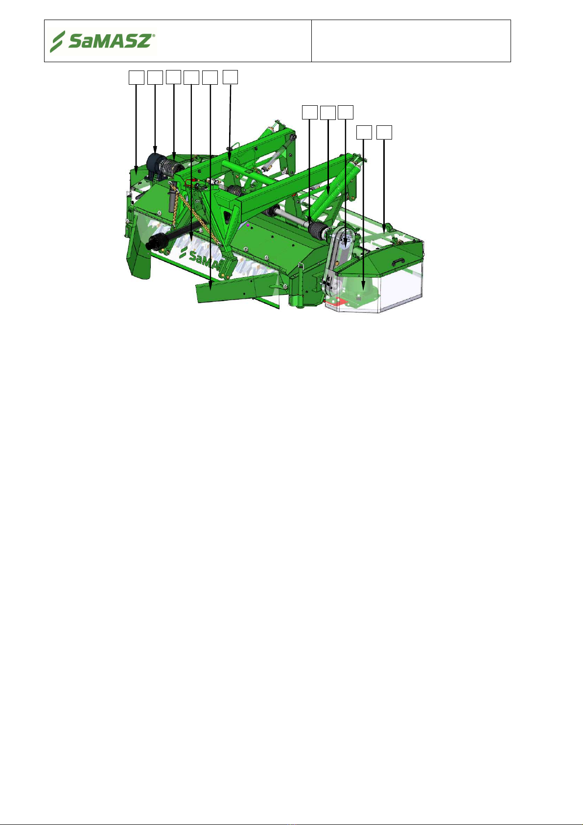
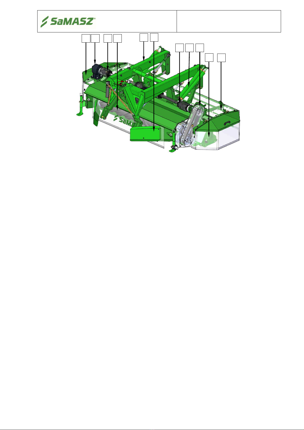
3.2. Design and working principle...............................................................................................................................5
3.3. Standard equipment and spare parts .....................................................................................................................7
4. SAFETY PRECATIONS .........................................................................................................................................8
4.1. General safety rules and regulations .....................................................................................................................9
4.2. Conditions of mounting mower on tractor.......................................................................................................... 10
4.3. Transport.............................................................................................................................................................10
4.3.1. Putting the mower onto another vehicle for transport ...................................................................................11
4.4. Working parts .....................................................................................................................................................12
4.5. PTO shaft............................................................................................................................................................ 12
4.6. Hydraulic assembly ............................................................................................................................................ 12
4.7. Safety curtains .................................................................................................................................................... 13
4.8. Residual risk .......................................................................................................................................................13
4.8.1. Danger of machine entanglement.................................................................................................................. 13
4.8.2. Danger of cutting injury ................................................................................................................................ 13
4.8.3. Danger of injury from liquid ejection out of hydraulic system .....................................................................13
4.8.4. Forbidden actions ..........................................................................................................................................13
4.9. Residual risk assessment..................................................................................................................................... 14
4.10. Safety labels and their meaning ..........................................................................................................................14
5. OPERATION.......................................................................................................................................................... 17
5.1. Attaching the mower to the tractor ..................................................................................................................... 17
5.2. Setting clearance between suspension frame and bumper base with indicator (option) ..................................... 19
5.3. Adjusting the length of support chains ...............................................................................................................19
5.4. Preparing the mower for transport ......................................................................................................................19
5.5. Mounting PTO shaft ...........................................................................................................................................20
5.6. Moving from transport to working position........................................................................................................21
5.7. Preparing the mower for work ............................................................................................................................21
5.8. Operation (mowing)............................................................................................................................................ 22
5.8.1. Essential information concerning mowing .................................................................................................... 22
5.8.2. Mower clogging ............................................................................................................................................24
5.8.3. Taking turns over swaths............................................................................................................................... 24
5.9. Dismounting mower from tractor ....................................................................................................................... 24
6. MOUNTING AND ADJUSTMENTS ...................................................................................................................25
6.1. Mounting and timing of the knives..................................................................................................................... 25
6.2. Replacing the knives...........................................................................................................................................25
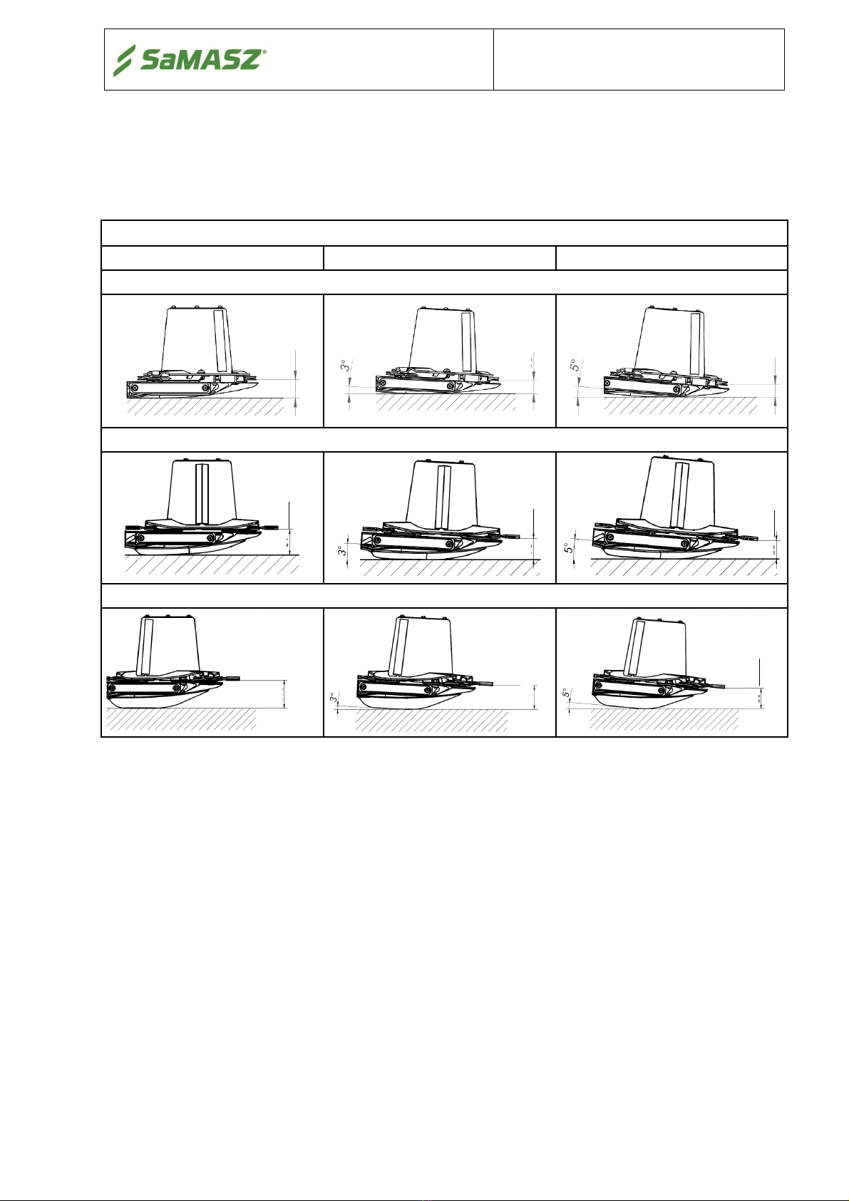
6.3. Adjusting the cutterbar........................................................................................................................................27
6.4. Adjusting the space between tine conditioner’s mask and its shaft .................................................................... 28
6.5. Replacing the conditioner’s tines........................................................................................................................ 28
6.6. Adjusting force of the pressure of roller conditioner..........................................................................................29
6.7. Adjusting pressure of the cutterbar using support springs ..................................................................................30
6.8. Maintenance and service.....................................................................................................................................31
6.8.1. Checking the knives and knife holders.......................................................................................................... 31
6.8.2. Control and tension of cogbelt ......................................................................................................................31
6.8.3. Daily maintenance.........................................................................................................................................32
6.8.4. After-season maintenance and storing of machine........................................................................................ 32
7. LUBRICATION .....................................................................................................................................................33
7.1. Cutterbar .............................................................................................................................................................33
7.2. Intersecting axis gears......................................................................................................................................... 34
7.3. Roller conditioner’s gearbox ..............................................................................................................................34
7.4. Bearings and joints .............................................................................................................................................35
8. MALFUNCTION AND THEIR REPAIRS.......................................................................................................... 37
9. DISASSEMBLY AND WITHDRAWAL FROM USE........................................................................................ 37
9.1. Scrapping ............................................................................................................................................................ 37
10. HYDRAULIC SCHEME ....................................................................................................................................... 38
11. WARRANTY CARD.............................................................................................................................................. 38
12. WARRANTY TERMS ........................................................................................................................................... 39
12.1. Warranty claims procedures ...............................................................................................................................39
12.2. Warranty repairs record ...................................................................................................................................... 40
APPENDIX CALCULATING AXIS LOAD ................................................................................................................41

Operator’s manual
Front disc mowers
KDF
-
2
-
1. IDENTIFYING THE MACHINE
Data plate is mounted to the mower’s main frame in the place shown below (Fig. 1).
Fig. 1. Data plate location Fig. 2. Data plate
Data plate includes:
-
name and adress of the manufacturer,
-
model year,
-
CE marking means, that the produce
-
version number,
conforms to 2006/42/EC Directive and
-
machine weight,
harmonized standards,
-
id number,
-
m
achine symbol,
-
barcode.
-
date of manufacture,
2. INTRODUCTION
This operator’s manual is essential for safe and proper use of this mower and should be read
before anyone operates this mower
.
It should be kept near the mower
for future use. If the
mower is used by other operator, it should be in working condition and include this operator’s
manual and all other basic equipment.
Operator’s manual is delivered with every machine so that the operator can familiarize himself
with the design, working principle, servicing and adjustment of the mower. The operator should
be familiar with common safety rules and procedures.
The mower is manufactured according to international safety rules.
Compliance with the safety precautions in this operator’s manual will enable safe operation.
Please contact your dealer if you have any queries relating to the operation and service of
the mower.

Operator’s manual
Front disc mowers
KDF
-
3
-
3. PROPER AND INTENDED USE
Mower KDF is equipped with the “Perfect Cut” cutting bar. In table 1 the mowing height
differences, depending on the inclination angle of the cutting bar are shown.
Tab. 1. Mowing height depending on cutterbar's inclination angle
„Perfect Cut” cutting bar
No tilt
3° tilt
5° tilt
Standard mowing height
Optional heights when using high mowing topping
Optional heights when using high mowing double topping
•The front mounted disc mower is intended for mowing green fodder such as grass and alfalfa
on permanent grassland (pastures), on crop fields without rocks, and forming loose rows of cut
fodder. The pasture or field being mown should be even and best if prepared by rolling. In
the event there is a majority of tall grass, the first and second mowing should be done at a
height of 2.4" - 2.8", while with a majority of short grass, at a height of 2". The last mowing
should be done a little higher - at 2.8" - 3.1" from the ground.
•
The front mounted disc mower with tine/roller conditioner is intended for mowing green fodder
such as grass and alfalfa on permanent grassland (pastures), on crop fields without rocks, and
forming loose rows of cut forage. As a result of the passing of the layers of the green fodder
through the flails or rollers, the grass stems are broken and a layer of wax is removed. This
facilitates and speeds up the drying process of the fodder by approximately 30 to 40%. The use
of rollers is especially recommended when mowing legumes such as alfalfa. The pasture or
field being mown should be even and best if prepared by rolling. This is especially true of
mowers with rollers as they tolerate rocks with a diameter of a few inches. If a larger stone is
picked up, stop and remove it as it could cause damage to the discs. With a majority of tall
grass, the first and second mowing should be done at a height of 2.4" - 2.8", while with
a majority of short grass it should be cut at a height of 2". The last cut should be done a little
higher - at 2.8" - 3.1"from the ground.
2.
8"
2
.1
"
1,7
"
2
.8
"
2
.4
"
4.3
"
3.5
"
3.1
"
3.6
"

Operator’s manual
Front disc mowers
KDF
-
4
-
WARNING
:
Use of the mower for purposes other than described above is forbidden. Improper
use can be dangerous and may lead to voiding the warranty. Mower should be
operated and repaired only by persons familiar with its detailed specifications and
with all applicable safety rules and regulations as well as the relative dangers.
Unauthorized modifications introduced to the mower will lead to voiding the
warranty
.
3.1. Technical data
Tab. 2. Specification of the mower KDF and KDF W
Model KDF 260 KDF 300 KDF 340 KDF 390 KDF 301W KDF 341 W
Working width
8
′
6
″
9
′
10
″
11
′
1
″
12
′
9
″
9
′
10
″
3,40 m
Number of knives [pcs.]
12 (6x2)
14 (7x2)
16 (8x2)
19 (9x2)
14 (7x2)
16 (8x2)
Tractor PTO rpm 1000 rpm
Tractor power required 54 kW
(70
HP
)
60 kW
(80
HP
)
66 kW
(90 HP
)
90 kW
(120
HP
)
74 kW
(100
HP
)
81 kW
(110
HP
)
Working capacity
V = 12 km/h
~ 2,8 ha/h ~ 3,5 ha/h
~ 4 ha/h ~ 4,6 ha/h
~ 3,5 ha/h ~ 4 ha/h
Swath width
2
′
11
″
-
3
′
7
″
4
′
3
″
-
4
′
11
″
4
′
3
″
-
5
′
3
″
4
′
3
″
-
5
′
11
″
4
′
3
″
-
4
′
11
″
4
′
3
″
-
4
′
11
″
Transport length
5
′
5
″
5
′
5
″
5
′
5
″
5
′
7
″
5
′
7
″
5
′
7
″
Transport width
8
′
6
″
9
′
10
″
11
′
1
″
12
′
9
″
9
′
1
0
″
9
′
10
″
Working width
10
′
4
″
11
′
8
″
12
′
11
″
14
′
5
″
11
′
8
″
13
′
3
″
Weight
1774 lbs.
2073 lbs.
2248 lbs.
2347
lbs.
2999 lbs.
3251 lbs.
Noise level
L
pA
101 ± 1 dB
100,5 ± 1 dB
L
Ama
x
112,5 ± 1 dB
112 ± 1 dB
L
Cpea
k
114 ± 1 dB
113,5 ± 1 dB
Tine/roller conditioner
shaft
- 818 rpm
W – Mowers with roller conditioner
Tab. 3.
Specification of the mower KDF S and KDF SL
Model KDF 301S
KDF 301SL KDF 341S
KDF 341SL
Working width
9
′
10
″
9
′
10
″
11
′
2
″
11
′
2
″
Number of knives [pcs.]
14 (7x2)
14 (7
x2)
16 (8x2)
16 (8x2)
Tractor PTO rpm
1000
rpm
Tractor power required 74 kW
(100
HP
)
74 kW
(100
HP
)
81kW
(110
HP
)
81kW
(110
HP
)
Working capacity
V = 12 km/h
~ 3,5 ha/h
~ 3,5 ha/h ~ 4 ha/h ~ 4 ha/h
Swath width
4
′7
″
-
5
′7
″
4
′7
″
-
5
′7
″
4
′7
″
-
5
′7
″
4
′7
″
-
5
′7
″
Tr
ansport length
5
′7
″
5
′7
″
5
′7
″
5
′7
″
Transport width
9
′
10
″
9
′
10
″
11
′
2
″
11
′
2
″
Working width
11
′
8
″
11
′
8
″
13
′
3
″
13
′
3
″
Weight
2777 lbs.
-
2954 lbs.
-
Number of conditioner’s
tines [pcs.]
58
108
68
128
Tine/roller conditioner shaft
818 rpm
Noise level
L
pA
99,5 ± 1 dB
L
Amax
111 ± 1 dB
L
Cpeak
113,5 ± 1 dB
S – Mowers with tine conditioner SL - Mowers with light weight swath conditioner
L
pA
– noise level related to 8 hour working time. Averaged in time acoustic pressure level corrected by
frequency characteristic A.
L
Amax
– maximum value corrected by frequency characteristic A of acoustic pressure level.
L
Cpeak
– peak level of acoustic pressure corrected by frequency characteristic C.

Operator’s manual
Front disc mowers
KDF
-
5
-
3
10
7
8
9
4
1
6
5
2
3.2. Design and working principle
Fig. 3a. Parts of SaMASZ front disc mower
1 – Suspension frame
2 – Main frame
3 – Cutterbar
4 – Intersecting axis gear I
5
–
Intersecting axis gear II
6 – Cutterbar drive shaft
7 – Swath discs
8 – Support springs
9 – Hydraulic cylinders
10
–
Safety guard
Drive from tractor’s rpm is transmitted through PTO shaft, intersecting axis gear I (4),
cutterbar drive shaft (6) and intersecting axis gear II (5) to the cutterbar (3). On the cutterbar, there
are discs with two knives each. The outer discs have additional forming drums. Cutterbar is
connected to the main frame (2) with suspension frame (1). On the suspension frame, there is the
mower’s triangle, which is designed to connect the mower to the tractor’s front 3-point linkage.
Over the cutterbar, there are safety guards (10).

Operator’s manual
Front disc mowers
KDF
-
6
-
Fig. 3b. Parts of SaMASZ front disc mower with tine conditioner
1 – Suspension frame
2 – Main frame
3 – Cutterbar
4 – Intersecting axis gear I
5 – Intersecting axis gear II
6 – Cutterbar drive shaft
7
–
Swath guide
8 – Support springs
9 – Hydraulic cylinders
10 – Safety guard
11 – Tine conditioner
12 – Tine conditioner drive shaft
13 – Gearbox
Drive from tractor’s rpm is transmitted through PTO shaft, intersecting axis gear I (4),
cutterbar drive shaft (6) and intersecting axis gear II (5) to the cutterbar (3). On the cutterbar, there
are discs with two knives each. The outer discs have additional forming drums. Apart from that,
drive from tractor’s rpm through intersecting axis gear I (4), tine conditioner driver shaft (12) and
gearbox (13) is transmitted to tine conditioner (11). Cutterbar is connected to the main frame (2)
with suspension frame (1). On the suspension frame, there is the mower’s triangle, which is
designed to connect the mower to the tractor’s front 3-point linkage. Over the cutterbar, there are
safety guards (10).
1
10
13
3
12
8
6
2
5
11
7

Operator’s manual
Front disc mowers
KDF
-
7
-
Fig. 3c. Parts of SaMASZ front disc mower with roller conditioner
1 – Suspension frame
2 – Main frame
3 – Cutterbar
4 – Intersecting axis gear I
5 – Intersecting axis gear II
6 – Cutterbar drive shaft
7
–
Swath guide
8 – Support springs
9 – Hydraulic cylinders
10 – Safety guard
11 – Roller conditioner
12 – Roller conditioner drive shaft
13 – Gearbox
Drive from tractor’s rpm is transmitted through PTO shaft, intersecting axis gear I (4),
cutterbar drive shaft (6) and intersecting axis gear II (5) to the cutterbar (3). On the cutterbar, there
are discs with two knives each. The outer discs have additional forming drums. Apart from that,
drive from tractor’s rpm through intersecting axis gear I (4), roller conditioner driver shaft (12) and
gearbox (13) is transmitted to roller conditioner (11). Cutterbar is connected to the main frame (2)
with suspension frame (1). On the suspension frame, there is the mower’s triangle which is
designed to connect the mower to the tractor’s front 3-point linkage. Over the cutterbar, there are
safety guards (10).
3.3. Standard equipment and spare parts
The mowers are sold with the following standard equipment:
warranty card,
operator’s manual with spare parts list,
cutting knives: additional set,
holders for warning plate and lights,
PTO shaft with friction clutch,
tractor’s triangle,
spray paint (150 ml).
Optional extra equipment:
warning plate with combined lights and reflectors,
warning triangle,
side shift adapter,
high mowing toppings / double toppings.
10
1
6
5
3
11
8
2
13
12
7

Operator’s manual
Front disc mowers
KDF
-
8
-
Tab. 4. Recommended PTO shafts for front disc mowers
Model Power
Length Moment Symbol Clutch Manufacturer
HP in Nm
KDF 260
74 33.46″-
50.63″520 8G5T085CE007001 Overrunning
clutch = 1200 Nm
Bondioli &
Pavesi
KDF 300
KDF 340
KDF 390
KDF 301 S/SL/W
100 39.76″-
60.75″710 8G7T101CE007002
KDF 341 S/SL/W
Fig. 4. PTO shaft lubrication points. Mounting directions
NOTICE:
Lubricate the PTO shaft with high quality multi-purpose grease every
50 shaft operating hours. The shaft should also be lubricated before and after
longer idle periods.
PTO shafts of other brands with equivalent parameters could be used afer SaMASZ permission.
NOTICE:
Optional extra equipment should be ordered separately.
The mower is equipped with such elements as holders and brackets used to mount warning lights
and plates. Combined lights and reflectors are mounted on the warning plates.
4. SAFETY PRECATIONS
The following precautions are for your safety. They must be read carefully
and followed by every person who operates or maintains the machine. Failure to follow these
safety precautions could result in serious injury or death to the operator, maintenance person or
bystanders and property damage to the machine and surrounding property.
Safety Signal Words
This manual and the safety labels attached to this equipment utilize signal words that signify
safety hazards with different levels of severity. Below are the words used and the definitions for
these words:
•DANGER indicates a hazardous situation which, if not avoided, will result in death
or serious injury
PTO shaft’s end without clutch
–
To be mounted on the
tractor’s side.
PTO shaft’s end with
overrunning clutch –
To be
mounted on mower’s side

Operator’s manual
Front disc mowers
KDF
-
9
-
•WARNING indicates a hazardous situation which, if not avoided, could result in
death or serious injury
•CAUTION indicates a hazardous situation which, if not avoided, could result in
minor or moderate injury
•NOTICE is used to address practices not related to physical injury
4.1. General safety rules and regulations
The following descriptions are for your safety: They must therefore be read
carefully and applied every time you use the machine.
The machine has been designed for use by one single operator.
When using, servicing, repairing, moving or storing the machine, the operator must wear safety
shoes, safety gloves plus ear protection and dust mask if necessary.
During use, the machine may give rise to dust, especially if the soil is dry. You are advised to
use a tractor with a cab fitted with filters in the ventilation system. Failing this, wear a dust
mask with filter to protect your respiratory tract.
Front axis of the tractor should be weighted to keep the balance. If need be, use front wheel
weights.
In order to keep steering conditions, impact on front axis should be at least 20% of the complete
tractor.
Be extremely careful whenever using hydraulic lift lever or buttons. Any operation with
hydraulic lift lever should be done from operator’s seat; DO NOT move the lever from outside
of a tractor.
In case of tractors equipped with EHR, operating with hydraulic lift is done by the buttons
mounted outside the tractor’s cabin. When operating be extremely careful.
When switching from mowing to transport position, remove the entire PTO shaft or at least one
end of the shaft from the tractor’s PTO so it cannot turn.
When attaching the mower to a tractor, the operator should wear protective gloves.
DO NOT operate the mower unless all safety guards are in place and operational. In addition,
any damaged protective aprons should be replaced with a new one
DO NOT exceed 1050 PTO rpm.
No person (except operator) should stand within danger area which is a minimum of 170’ from
any operating part, especially when operating near roads and in areas with stones and other
debris.
Be certain that children and animals are at a safe distance away from the machine
.
IMPORTANT: Maintenance and adjustment should ONLY be done after the following has
occurred:
tractor’s engine has been stopped
and ignition key has been taken out,
all rotating parts have come to complete standstill (NOTICE: cutting knives
will rotate for several minutes after engine is turned off),
the cutterbar is on the ground, and
Never tamper with or remove safety devices on the machine or make them inoperable.
Before starting work and periodically thereafter, replace any damaged, missing and/or worn
knives and knife holders.
When driving on public roads always comply with local traffic regulations, especially those
concerning warning lights.
When the mower is lifted for repair on 3-point linkage, it should be secured against falling by
mechanical support or by chain.
The bolts and other fasteners have to be periodically checked and, if necessary, tightened or
replaced. DO NOT work with damaged or worn fasteners.
Never lift the mower on tractor linkage when the drive is operating and the cutting discs are
rotating.

Operator’s manual
Front disc mowers
KDF
-
10
-
When operating the mower, the tractor should always be equipped with operator protection that
is required by laws and regulations.
Never start the mower when the mower blades are off the ground.
Before you start the tractor make sure that all drives are turned off and the levers that turn the
hydraulics are in neutral position.
Never leave tractor’s engine running without supervision. Before you leave the tractor, turn off
the engine and remove the key from tractor’s ignition.
DO NOT operate the mower when driving the tractor backwards.
Permissible inclination of the mower on a slope when working and during transport is 8°.
Exceeding this incline can result in mower tipover.
Never stand between tractor and mower unless tractor and mower are secured against moving
by the tractor’s brake.
If any maintenance must be done under an elevated mower, it must be blocked or otherwise
secured against falling.
When the parts of the mower need replacement, use only original spare parts as described in the
spare parts list. Pay particular attention to PTO shaft’s guards and mower’s and tractor’s spline
shaft guards.
Hydraulic hoses are potentially very dangerous. Do the following to minimize any hazards:
Hydraulic hoses should be periodically checked and if any damage to the hoses have
occurred or if they have been used more than 5 years, replace with new ones.
Never use scotch tape to repair hydraulic hoses.
When connecting hydraulic hoses to tractor’s hydraulic connectors, make sure that
the tractor’s or mower’s hydraulic system is not under pressure.
The mower should be stored under a roof and in a way as to not be hazardous bot people or
animals.
In the event of an accident involving this mower in a field or on a road, follow all applicable
first aid procedures and contact SaMASZ technical service.
Mower should be kept clean, so as to avoid danger of fire.
4.2. Conditions of mounting mower on tractor
Prior to the mounting operation, be sure that the tractor and mower hitches are compatible and
that the tractor's hitch load is adequate for the machine which is to be mounted or attached.
Prior to mounting the machine, examine the technical condition of the mower's hitch assembly
and tractor's 3-point linkage.
Use only genuine cotter pins to mount the mower on a tractor.
4.3. Transport
The lifting, handling and transporting operations can be very dangerous unless they are carried
out with the utmost caution. Have all persons not involved in the actual work move away from the
area and limit the zone where the operations are to be carried out. Also make sure that the area in
which the operations take place is clear and that there is a sufficient escape route, i.e. a free, safe
zone to which the operators can quickly move if the load should fall.
The safety hooks and ropes used to lift the machine must be of an adequate carrying capacity.
To minimize the risk of serious injury or death, do the following:
When the machine is converted from the transport position to the work position and vice versa,
you could be pinched or crushed by some of its parts. Take extra care when carrying out these
maneuvers and have all persons keep well clear of the danger zone.
Do not change position of the mower until there are no people or animals around (pay particular
attention to children).
While transporting the mower, put a warning plate with combined lights and reflectors and
warning triangle on the mower.

Operator’s manual
Front disc mowers
KDF
-
11
-
During transport, always put the mower in its proper and safe transport position. See section 5.3.
Before putting the mower in transport position, make sure that the tractor’s PTO is turned off
and all rotating parts have come to a complete stop.
Do not drive over 25 km/h (15 mph). Drive slower if road conditions are poor, especially on
irregular surfaces or steep slopes.
The behavior of the tractor on the road, such as its turning and braking capacities, are affected
by the implements mounted.
When driving on the road after work, check to make sure that the tires and soil working tools
are clean to prevent the road surface from becoming dirty.
Make sure that the machine is not damaged during transport.
4.3.1. Putting the mower onto another vehicle for transport
The driver and the carrier are responsible for the mower’s transport safety. Equipment and
parts must be secured during transport. To put the mower onto another vehicle in a safe way, please
obey the following rules:
Transport should be done by qualified and specifically trained personnel,
Grab the mower by any lifting devices only in places indicated by hook sign (Fig. 5),
For mower lifting, use only lifting devices with hoisting capacity larger than mower’s
weight shown in data plate. This also applies to ropes and chains used for lifting,
Do not lift if transport belts, belt suspensions, ropes are damaged. Whenever damage to
these parts occurs, replace with new ones,
When mounting slings, chains, handles etc., always set the machine's center of gravity
properly,
To safely support the machine, use ropes of adequate length so that the angle between them
is no greater than 120°, and the angle between the strand and the vertical is no greater than
60°,
Lift the machine with the utmost caution and move it slowly,
No one should be within the range of action of the lifting equipment when any transporting
operations are being carried out,
Collapsible parts should be blocked in transport position,
When the mower is on the vehicle’s trailer, the machine should be secured against moving.
Fig. 5. Transport holders
Transport holder

Operator’s manual
Front disc mowers
KDF
-
12
-
Fig. 6. Location of centre of gravity KDF mowers
Tab. 5. Location of centre of gravity
Dimension
[ft in]
Model
KDF
260
KDF
300
KDF
340
KDF 390 KDF 301
S(SL)
KDF 341
S(SL)
KDF 301
W
KDF 341
W
A 2′5″2′6″2′11″1′11″2′11″2′12″2′11″3′4″
B 2′1′11″2′3″2′7″1′10″1′11″1′11″1′11″
C 5′6″6′2″6′11″7′8″6′6′8″5′10″6′10″
D 4′9″5′5″6′6′9″5′7″6′3″5′9″6′1″
4.4. Working parts
Before operating the mower check knife’s and knife holder’s condition.
Worn or damaged knives or knife holders should be immediately replaced with new one.
4.5. PTO shaft
Before operating, read bar manufacturer's manual placed on the bar. Follow all safety
precautions in that manual.
Use only PTO shafts recommended by mower’s manufacturer with guards in good condition.
In order to operate safely, use only undamaged PTO shafts and shields. Damaged PTO shafts
and shields must be repaired or replaced with new ones before use.
4.6. Hydraulic assembly
Hydraulic assembly is under high pressure. Hydraulic oil under pressure may penetrate skin
and cause serious injury or death. Skin and eyes should be protected when working around this
assembly.
In case of injury caused by a liquid under pressure, call a doctor immediately.
Hydraulic hoses can be connected to the tractor's hydraulics provided that both the tractor’s and
the mower's hydraulic assemblies are not under pressure. To remove the pressure from the
hoses, start the tractor's hydraulic valves several times with the tractor off.
When looking for oil leaks, do so safely. Use a cardboard card. Do not touch any potential
leaks until the entire hydraulic assembly has been relieved of pressure.
Use only hydraulic oil featuring oil purity class 9 - 10 in accordance with NAS 1638.
When using hydraulic hoses:
Avoid stretching the hoses when operating.
Do not allow hydraulic hoses to get deflected.
Do not expose hydraulic hoses to contact with any sharp edges.
If damaged or worn, replace the hoses with new ones.
Useful life for hydraulic hoses is 5 years from their production date.
B
A
C
D

Operator’s manual
Front disc mowers
KDF
-
13
-
4.7. Safety curtains
SaMASZ mowers feature standard safety curtains (1) for self-mounting. In order to mount the guard
properly, put it on a mower and secure with catches (2) and front guard (3) Fig. 7. Examine
condition of guards and its mounting on a regular basis. Fix immediately if damaged and replace if
missing. Do not operate mower without safety curtains.
Fig. 7. Mounting safety curtains on the mower
4.8. Residual risk
Despite the fact that SaMASZ Białystok, the manufacturer of the mower, has taken great care
in the design and manufacturing of the mower, certain risks during mower operation and
maintenance are unavoidable. A major source of risk that could result in serious injury or death can
occur during the performance of these operations.
Major source of risk follows performance of these operations:
operation of mower by minors,
operation by individuals who have not read the operator's manual and safety labels,
operation of mower by persons under influence of alcohol or other substances,
not being cautious during transportation and moving mower during operation,
transport of persons who are on the machine,
presence of persons and animals within the mower operation range,
performing servicing and machine adjustments with the engine on.
4.8.1. Danger of machine entanglement
This risk occurs when (1) changing position of a mower, (2) operating near rotating parts, and
(3) working without safety guards. During operation, maintenance and adjustment, always wear
protective gloves, shoes and clothes without loose parts, belts and so on. Always comply with
safety labels placed on the mower.
4.8.2. Danger of cutting injury
This risk occurs during replacement of working parts with sharp edges. During any
maintenance work, always use safety gloves.
4.8.3. Danger of injury from liquid ejection out of hydraulic system
During connection of hydraulic hoses to hydraulic connectors, be sure that tractor’s or
mower’s hydraulic system is not under pressure. Regularly check hydraulic hoses for leaks.
4.8.4. Forbidden actions
During mower’s operation, do not do the following:
never unblock the mower, make any regulations or repairs of the mower while it is in
motion,
never change order of operation and maintenance activities described in operator’s manual,
3
1
2
4
4

Operator’s manual
Front disc mowers
KDF
-
14
-
never operate the mower when it is not in working order or has damaged safety guards,
never get your hands and legs close to rotating parts of the mower,
during repair and maintenance of the mower, always comply with descriptions included in
operator’s manual. Always do these activities when the tractor’s drive is off,
never operate the mower under influence of alcohol, drugs, or strong medicine that impair
your attention,
do not wear clothes or jewelry that are too loose or too tight. Too loose clothing or jewelry
may be pulled in by the rotating parts of the mower,
the mower should not be operated by children or by handicapped people,
When describing residual risk, the mower complies with the state of the art in technology on the
date it was manufactured.
4.9. Residual risk assessment
Residual risk occurs from not complying with the instructions and safety precautions. Such risk can
be minimized by doing the following:
thorough familiarizing yourself with operator’s manual,
allow no persons on the machine when operating,
allow no persons within the mower operation range,
adjust, maintain and lubricate the machine with the engine off,
only skilled persons should perform repairs of the machine,
children and strangers must keep away when the machine is operating,
When the risk of exposure to noise cannot be avoided or eliminated by any
protective means or organization of work, the employer (farmer) must:
1) provide the operator with individual means of noise protection if the noise
level in work place exceeds 80 dB.
2) provide the operator with individual means of noise protection and supervise
the correctness of its usage, if the noise level in work place reaches or exceeds
85 dB.
4.10. Safety labels and their meaning
Safety labels are critical to safe use of this mower. They must be read, understood and followed.
Also, be sure that:
All warning decals are clean and legible
All lost or damaged decals are replaced by ordering new decals from your dealer or supplier
All persons using this mower have read the section of this manual explaining the meanings of
these labels
All spare part used for repair of the mower should have all safety labels provided by the
manufacturer.
N-01
Be extremely careful when
PTO shaft is rotating!
N-02
Caution – cutting knives.
Approach during operation
is forbidden!
N-03
Caution – read the
operator’s manual before
putting the mower into
operation!
N-04
Caution – while making
repairs the machine must be
stopped

Operator’s manual
Front disc mowers
KDF
-
15
-
N-05
CAUTION – belt
transmission, be extremely
careful!
N-06
Caution – rotating parts
N-07
Operating is forbidden
when any person is within
the danger area of 170’!
N-09
Caution: rotor
N-11
N-14 N-15
N-23
Watch out: power lines
N-35
Cutterbar "Perfect Cut"
N-40
Signs indicating transport
holders
N-48
Lower side safety guards
before turning the drive on
N-49
Do not get too close to
the hoist of the tractor
during operation of the
hoist
N-50
Do not stay in the swinging
area of mower’s parts
N-113
N-117
Under pressure. Consult
technical manual for
service procedures
N-162 N-167
Do not remain on
the machine while
driving
N-168
Do not touch the
machine before the
rotating parts have
not come to a
complete standstill

Operator’s manual
Front disc mowers
KDF
-
16
-
N-204
Use the required Personal
Protective
N-205
Use the required Personal
Protective
N-206
Use the required Personal
Protective
N-175 N-212
Conditioner's rpm
N-213
Conditioner's intensity
N-224
Do not open and remove
safety guards with motor
operating
CAUTION:
Any spare part used for repair of the mower should have all warning decals
provided by the manufacturer.
Fig. 8a. Warning decals placed on the mower without conditioner
N-14; N-15
N-162; N-204
N
-
205; N
-
206
N-01; N-02; N-03
N-04; N-06; N-07
N-23; N-48; N-49
N-50; N-117
N-167; N-168
N-224
N-113
N-187
N-109

Operator’s manual
Front disc mowers
KDF
-
17
-
Fig. 8b. Warning decals placed on the mower with tine conditioner
Fig. 8c. Warning decals placed on the mower with roller conditioner
5. OPERATION
5.1. Attaching the mower to the tractor
WARNING:
Before beginning to use this machine, do the following:
- Read manual, especially safety precautions in section 4.
- Make sure you are familiar with all controls and functions.
- Make sure all safety devices are in place and working. Fix or replace if not
working or damaged.
- Replace protective cover if damaged.
WARNING:
- Only hitch and unhitch machine on a flat surface with compact dirt.
- Keep everyone away from area between mower and tractor.
- Be careful near link road zone of tractor's rear power lift. Contains sharp
parts.
N-175
N-212
N
-
213
N-14; N-15
N-162; N-204
N
-
205; N
-
206
N-01; N-02; N-03
N-04; N-05; N-
09
N-06; N-07 N-23;
N-48; N-49
N-50; N-117
N-167; N-168
N-113
N
-
175
N-14; N-15
N-162; N-204
N
-
205; N
-
206
N-01; N-02; N-03
N-04; N-05; N-
09
N-06; N-07 N-23;
N-48; N-49
N-50; N-117
N-167; N-168
N-113

Operator’s manual
Front disc mowers
KDF
-
18
-
The mower is attached directly onto hitch triangle which is mounted to tractor's front 3-point
linkage (hitch triangle, Cat. II is delivered as mower's standard equipment).
Mount triangle (1) on tractor's lower arms, connect with pins (2), and then secure with spring
cotters (3). Next install upper connector (4), connect with pins (5) and secure both with spring
cotters (3) (Fig. 9).
Fig. 9. Mounting hitch triangle, cat. II
After the mower has been attached to tractor, check the balance and steerability of tractor-
mower set. To do this, calculate to formulas given in the appendix or weigh the set, and then drive
on the scales only with front axis of the tractor (the mower must be in transport position – lifted
upwards). If the pressure on the rear axis is at least 20% of the whole set’s pressure, it means the set
is stable. If not, the rear axis should be balanced. After having mounted the hitch triangle on the 3-
point linkage drive perpendicularly to the mower, using upper strand set the hitch triangle so it is
parallel to the machine's triangle (Fig. 10), lift the 3-point linkage until the mower is in the air and
the triangle in place. Secure the hitch triangle with pin and connect it with spring cotter. Finally
adjust the length of chains (it. 5.3).
Fig. 10. Mounting the mower on hitch triangle, cat. II
For front 3-point linkage lifters with forced pressure (cylinders of front lifter are under pressure
when being lowered) there is a risk that the machine is damaged when being lowered. Excess
pressure of the mower on the ground may cause damage to the mower's hitch, damage to the entire
machine, excess stretching or damaging the support chains.
1.
-
Hitch triangle Cat. II
2.
-
Lower strand pin
3.
-
Spring cotter
4.
-
Upper link
5.
-
Upper link pin
6.
- Safety pin for protection against machine
disconnection
4
3
1
2
5
6
3
Shafts end with
overrunning
clutch
Adjust, mount and
block the support
chain
Adjust the proper
inclunation by means
of upper link and
block it.
Adjust the space
between suspension
frameand rubber safety
bumper to about
30
cm
Secure the hitch
pin with cotter
Block the pins
This manual suits for next models
9
Table of contents
Other SaMASZ Lawn Mower manuals

SaMASZ
SaMASZ KBRP 160 User manual

SaMASZ
SaMASZ KDF 390 User manual

SaMASZ
SaMASZ KDD 861 User manual

SaMASZ
SaMASZ TORO 260 User manual

SaMASZ
SaMASZ SAMBA 240 User manual

SaMASZ
SaMASZ XT 390 User manual

SaMASZ
SaMASZ KBRP 160 User manual

SaMASZ
SaMASZ KDF 260 User manual

SaMASZ
SaMASZ KT 261 User manual

SaMASZ
SaMASZ KDT 180 User manual

SaMASZ
SaMASZ KDF 260 User manual

SaMASZ
SaMASZ KDC 260 S User manual

SaMASZ
SaMASZ KDTC 260 User manual

SaMASZ
SaMASZ KWT 550 User manual

SaMASZ
SaMASZ K2BF 210 User manual

SaMASZ
SaMASZ Z 010 User manual

SaMASZ
SaMASZ K2BF 210 User manual

SaMASZ
SaMASZ KDC 260 User manual

SaMASZ
SaMASZ Z 010/1 User manual

SaMASZ
SaMASZ KDD 860 User manual