SaMASZ KT 261 SL User manual

SaMASZ Sp. z o.o.
Poland, 16-060 Zabłudów, ul. Trawiasta 1
Established
–
1984
NIP PL-966-159-29-76
tel. (+48) (85) 664 70 31
fax (+48) (85) 664 70 41
e-mail: samasz@samasz.pl
www.samasz.pl
OPERATOR’S MANUAL
REAR DISC MOWER WITH
CENTRAL SUSPENSION
KT 261 - 8'7''
KT 261 H - 8'7''
KT 301 - 9'10''
KT 301 H - 9'10''
KT 341 - 11'2''
KT 341 H - 11'2''
KT 261 S - 8'7''
KT 261 SH - 8'7''
KT 261 SL - 8'7''
KT 261 SLH - 8'7''
KT 301 S - 9'10''
KT 301 SH - 9'10''
KT 301 SL - 9'10''
KT 301 SLH - 9'10''
KT 261 W - 8'7''
KT 261 WH - 8'7''
KT 301 W - 9'10''
KT 301 WH - 9'10''
S / SL – Swath conditioner/ light weight swath conditioner
H – Hydro-pneumatic suspension
W – Swath rollers
IN541USA006
29-03-2017
EDITION №6
Translation of original manual
Serial No.

DO NOT
TURN ON THE MOWER IF THE
MOWER IS NOT IN WORKING
POSITION
DO NOT
RESTORE THE MOWER INTO
TRANSPORT POSITION BEFORE
THE CUTTING DISCS HAVE NOT
COME TO A COMPLETE STOP
DO NOT
OPERATE THE MOWER WHEN
ANY PERSON REMAINS WITHIN
THE DANGER AREA OF 170’
FROM THE MOWER
NOTE:
Keep this manual for future reference.
Comprehensively tested construction and proper choice of materials ensure high reliability and
durability of our products.
Congratulations on your mower purchase and we know you will be satisfied from its use.
Recommended mower inclination towards the travel
direction is approx. 0°-5°. Mowing in the vertical position is
also allowed. Inclination of the mower in the opposite
direction will cause permanent damage to the cutterbar.

Operating manual
Rear disc mower with central suspension
- hydro-pneumatic or spring suspension
- 1 -
1. IDENTIFYING THE MACHINE ....................................................................................................................................2
2. INTRODUCTION .............................................................................................................................................................2
3. PROPER AND INTENDED USE.....................................................................................................................................3
3.1. Technical data ................................................................................................................................................................4
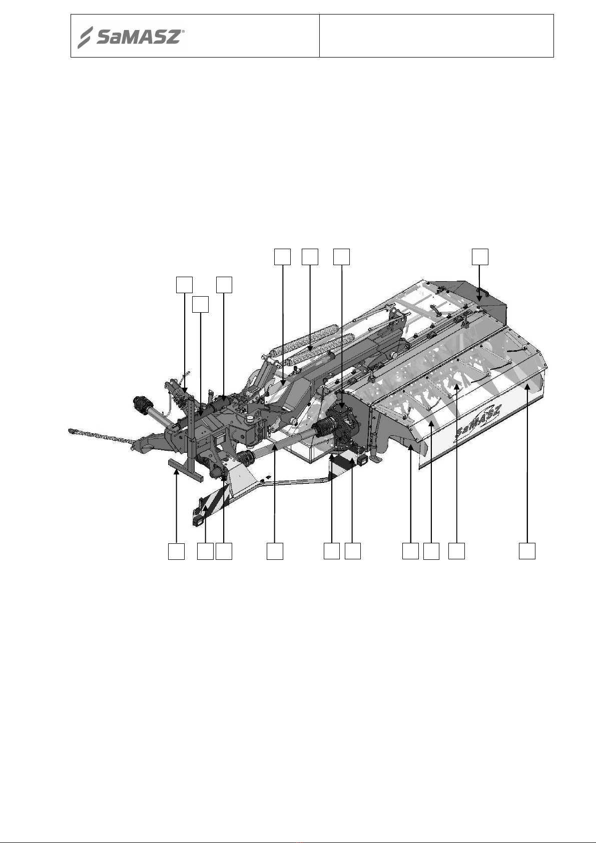
3.2. Design and working principle........................................................................................................................................6
3.3. Standard equipment and spare parts...............................................................................................................................9
4. SAFETY PRECAUTIONS..............................................................................................................................................10
4.1. General safety rules and regulations ............................................................................................................................11
4.2. Conditions of mounting mower on tractor ...................................................................................................................12
4.3. Transport......................................................................................................................................................................12
4.3.1. Placing the mower onto a transport vehicle ........................................................................................................13
4.4. Working parts .............................................................................................................................................................. 14
4.5. PTO shaft ..................................................................................................................................................................... 14
4.6. Safety curtains.............................................................................................................................................................. 14
4.7. Residual risk ................................................................................................................................................................15
4.7.1. Danger of machine entanglement........................................................................................................................15
4.7.2. Danger of cutting injury......................................................................................................................................15
4.7.3. Danger of injury from liquid ejection out of hydraulic system ...........................................................................15
4.7.4. Forbidden actions................................................................................................................................................ 15
4.7.5. Residual risk assessment ..................................................................................................................................... 15
4.8. Safety labels and their meaning ...................................................................................................................................16
4.9. Design and operation of hydraulic safety breakaway device .......................................................................................20
5. OPERATION OF THE MOWER ..................................................................................................................................21
5.1. Attaching the mower to the tractor...............................................................................................................................21
5.2. Mounting PTO shaft .................................................................................................................................................... 22
5.3. Preparing mower for operation – mower with hydro-pneumatic suspension ............................................................... 23
5.3.1. Gas pressure in the accumulator and in the entire system for each mower model .............................................. 24
5.4. Preparing mower for operation – mower with spring suspension ................................................................................ 24
5.5. Operating the mower....................................................................................................................................................25
5.5.1. Essential information concerning mowing.......................................................................................................... 25
5.5.2. Mower clogging ..................................................................................................................................................26
5.6. Preparing the mower for transport ...............................................................................................................................26
5.7. Preparing the mower for transport on public roads ......................................................................................................27
5.8. Moving from transport to working position................................................................................................................. 28
5.9. Disconnecting mower from tractor ..............................................................................................................................29
6. MOUNTING AND ADJUSTMENTS ............................................................................................................................29
6.1. Assembling / disassembling main frames ....................................................................................................................29
6.2. Mounting and timing of cutting blades ........................................................................................................................30
6.3. Blade replacement........................................................................................................................................................30
6.4. Adjusting the cutterbar................................................................................................................................................. 31
6.5. Setting mowing height ................................................................................................................................................. 33
6.6. Use and adjustment of load reducing chain..................................................................................................................34
6.7. Adjusting cutterbar’s pressure on the ground by means of support springs.................................................................34
6.8. Adjustment of the clearance between the cover and the roller of the conditioner........................................................35
6.9. Replacing conditioner tines..........................................................................................................................................35
6.10. Adjusting force of the pressure of roller conditioner ................................................................................................... 36
6.11. Maintenance and service..............................................................................................................................................37
6.11.1. Checking the blades and blade holders ...............................................................................................................37
6.11.2. Checking the tension of tine and roller conditioners’ driving chain.................................................................... 37
6.11.3. Daily maintenance...............................................................................................................................................38
6.11.4. After-season maintenance and storing of machine..............................................................................................38
7. LUBRICATION............................................................................................................................................................... 39
7.1. Cutterbar ......................................................................................................................................................................39
7.2. Intersecting axis gears..................................................................................................................................................39
7.3. Roller conditioner’s gearbox........................................................................................................................................40
7.4. Bearings .......................................................................................................................................................................41
7.5. Risks present when lubricating ....................................................................................................................................41
8. MALFUNCTIONS AND THEIR REPAIRS.................................................................................................................42
9. DISASSEMBLY AND WITHDRAWAL FROM USE .................................................................................................43
9.1. Scrapping .....................................................................................................................................................................43
10. HYDRAULIC SCHEME.................................................................................................................................................43
10.1. Hydraulic scheme of rear disk mower with swath conditioner ....................................................................................43
10.2. Hydraulic scheme of rear disk mower with hydro-pneumatic suspension ...................................................................44
11. WARRANTY CARD....................................................................................................................................................... 45
12. WARRANTY TERMS .................................................................................................................................................... 45
12.1. Warranty claims procedures.........................................................................................................................................45
12.2. Warranty repairs record ...............................................................................................................................................46
APPENDIX CALCULATING AXIS LOAD ..........................................................................................................................47

Operating manual
Rear disc mower with central suspension
- hydro-pneumatic or spring suspension
- 2 -
1. IDENTIFYING THE MACHINE
Data plate (Fig. 2) is mounted to the mower’s main frame in the place shown below in Fig. 1.
Fig. 1.
Data plate location
Fig. 2.
Data plate
Data plate includes:
-
name and adress of the manufacturer,
-
model year,
-
CE marking means, that the produce
-
version number,
conforms to 2006/42/EC Directive and
-
machine weight,
harmonized standards,
-
id number,
-
machine symbol,
-
barcode.
-
date of manufacture,
2. INTRODUCTION
This operator’s manual is essential for safe and proper use of this mower and should be read
before anyone operates this mower
.
It should be kept near the mower
for future use. If the
mower is used by another operator, it should be in working condition and include this
operator’s manual and all other basic equipment.
Operator’s manual is attached to every machine in order that the operator can familiarize
himself with design, working principles, service and adjustment of the mower. The operator
should be familiar with common safety rules and procedures.
The mower is manufactured according to international safety rules.
Compliance with the safety precautions in this operator’s manual will help to enable safe
operation.
Please contact your dealer if you have any queries relating to the operation and service of
the mower.
This operator’s manual is an indispensable part of any machine and is intended to
familiarize future user with principles of proper operation and use of the machine as well as
the risks involved.

Operating manual
Rear disc mower with central suspension
- hydro-pneumatic or spring suspension
- 3 -
3. PROPER AND INTENDED USE
Rear disc mower is equipped with the Perfect Cut cutterbar. Table 1 shows the mowing height
differences, depending on the tilt angle of the cutterbar.
Tab. 1. Mowing height depending on the kind of the cutterbar and its tilt angle
„Perfect Cut” cutting bar
No tilt
3° tilt
5° tilt
Standard mowing height
Optional heights when using high mowing topping
Optional heights when using high mowing double topping
The rear mounted disc mower is intended to mow green fodder: grass, alfalfa and such on
permanent grassland (pastures), on crop fields without rocks, and to form loose rows of cut
fodder. The pasture or field being mown should be even, best if prepared by rolling. In
the event of a majority of tall grass the first and second mowing should be done at a height of
2.4" - 2.8", while with a majority of short grasses at a height of 2". The last mowing should be
done a little higher - at 2.8" - 3.1" from the ground.
The rear mounted disc mower with crop scarifier/rollers is intended to mow green fodder:
grass, alfalfa and such on permanent grassland (pastures), on crop fields without rocks, and to
form loose rows of cut fodder. As a result of the passing of the layers of the green fodder
through the flails or rollers the grass stems are broken and a layer of wax is removed. This
facilitates and speeds up the drying process of the fodder by approximately 30 to 40%. The use
of rollers is especially recommended when mowing legumes such as alfalfa. Rollers are
particularly recommended for mowing grass legume such as alfalfa. The pasture or field being
mown should be even, best if prepared by rolling. This is especially true of mowers with rollers
as they tolerate rocks with a diameter of a few inches. If a larger stone is picked up stop and
remove it as it could cause damage of the discs. With a majority of tall grasses the first and
second mowing should be done at a height of 2.4" - 2.8", while with a majority of short grasses
at a height of 2". The last mowing should be done a little higher - at 2.8" - 3.1" from the
ground.
NOTE: Grass, which has not grown much should be mowed with zero angle inclination
.
2.
8
"
2
.1"
1.
7"
3.6
"
3.6
"
3.6
"
4.3
"
3.5
"
3.2

Operating manual
Rear disc mower with central suspension
- hydro-pneumatic or spring suspension
- 4 -
WARNING:
Use of the mower for purposes other than described above is forbidden. Improper
use can be dangerous and may lead to voiding of the warranty. Mower should be
operated and repaired only by people familiar with its detailed specifications and
with all applicable safety rules and regulations and with the relative dangers.
Unauthorized modifications to the mower will lead to voiding the warranty.
3.1. Technical data
Generally, KT mowers can divided into two groups:
- mowers with hydro - pneumatic suspension
- mowers with spring suspensions
The hydro-pneumatic suspension replaces the traditional springs. This significantly improves
the comfort of mower operation. The operator thus can quickly set the pressure of the cutterbar on
the ground with use of the tractor’s hydraulics. Additionally the latter is integrated with the
hydraulic safety device.
Emitted noise: up to 105 dB. Noise measured by noise meter from 3' 3" distance from
the machine in motion in final test area.
The technical specifications for the above mentioned groups are presented below.
Tab. 2. Technical data – Rear disk mower with support springs (with hydro-pneumatic suspension)
Mower type: KT 261 (H) KT 301 (H) KT 341 (H)
Wide conditioner
Mowing width
8' 7''
9' 10''
11' 2''
Number of blades [pcs]
12 (2 x 6)
14 (2 x 7)
16 (2 x
8)
Tractor PTO speed
540 rpm (
optional
:
1,000 rpm)
Tractor power
od 50 kW (70 HP)
od 58 kW (80 HP)
od 65 kW (90 HP)
Tractor 3
-
point linkage category
II
Working capacity
~ 2.8 ha/h
~ 3.5 ha/h
~ 4.0 ha/h
Transport height
10' 2''
11' 6''
13' 9''
Transpo
rt width
6' 7''
6' 7''
6' 7''
The width of
the
working system
15' 5''
16' 8''
18' 1''
Weight
2,205
lbs.
(2,106
lbs.
)
2,336
lbs.
(2,237
lbs.
)
2,491
lbs.
(2,403
lbs.
)
PTO shaft with unidirectional
clutch
540 Nm
Line cutting speed
86.2 m/s
Disc rotation
al speed
3
,
078 rpm
Noise level
L
pA
76.0 ± 1.5 dB
L
Amax
76.5 ± 1.5 dB
L
Cpeak
98.5 ± 1.5 dB
H – Mower with hydro-pneumatic suspension
L
pA
– noise level related to 8 hour working time. Averaged in time acoustic pressure level corrected by
frequency characteristic A.
L
Amax
– maximum value corrected by frequency characteristic A of acoustic pressure level.
L
Cpeak
– peak level of acoustic pressure corrected by frequency characteristic C.

Operating manual
Rear disc mower with central suspension
- hydro-pneumatic or spring suspension
- 5 -
Tab. 3. Technical data – Rear disk mower with support springs with swath conditioner / with light weight
swath conditioner (with hydro-pneumatic suspension)
Mower type: KT 261 S (H) KT 261 SL (H) KT 301 S (H) KT 301 SL (H)
Wide conditioner
Mowing width
8' 7''
8' 7''
9' 10''
9' 10''
Number of blades [pcs]
12 (2 x 6)
12 (2 x 6)
14 (2 x 7)
14 (2 x 7)
Tractor PTO speed
1,000 rpm
Tractor power od 66 kW
(90 HP)
od 66 kW
(90 HP)
od 66 kW
(90 HP)*
od 66 kW
(90 HP)
Tractor 3
-
point linkage category
II
Working capacity
~ 2.
8 ha/h
~ 2.8 ha/h
~ 3.5 ha/h
~ 3.5 ha/h
Transport height
10' 2''
10' 2''
11' 6''
11' 6''
Transport width
6' 7''
6' 7''
6' 7''
6' 7''
The width of
the
working system
15' 5''
15' 5''
16' 8''
16' 8''
Weight 2,866 lbs.
(2,843
lbs.
)
2,866 lbs.
(2,755
lbs.
)
3,120 lbs.
(
3,131
lbs.
)
2,976 lbs.
(
2,888
lbs.
)
PTO shaft with unidirectional
clutch
1,000 rpm
Line cutting speed
86.2 m/s
Disc rotational speed
3
,
078 rpm
Noise level
L
pA
76.0 ± 1.5 dB
L
Amax
76.5 ± 1.5 dB
L
Cpeak
98.5 ± 1.5 dB
* Minimum tractor weight – 11,023 lbs. is required.
S/SL – Mower
with swath conditioner
/
with light weight swath conditioner
Tab. 4. Technical data – Rear disk mower with swath rollers (with hydro-pneumatic suspension)
Mower type: KT 261 W (H) KT 301 W (H)
Wide conditioner
Mowing width
8' 7''
9' 10''
Number of blades [pcs]
12 (2 x 6)
14 (2 x 7)
Tractor PTO speed
1,000 rpm
Tractor power
od 66 kW (90 HP)
od 66 kW (90 HP)
*
Tractor 3
-
point linkage category
II
Working capacity
~ 2
.8 ha/h
~ 3.5 ha/h
Transport height
10' 2''
11' 6''
Transport width
6' 7''
6' 7''
The width of
the
working system
15' 5''
16' 8''
Weight
3,065 lbs.
(2,999 lbs.)
3,284 lbs.
(3,218 lbs.)
Articulated telescopic shaft with
unidirectional clutch
1,000 rpm
Line cutting speed
86.2 m/s
Disc rotational speed
3
,
078 rpm
Noise level
L
pA
76.0 ± 1.5 dB
L
Amax
76.5 ± 1.5 dB
L
Cpeak
98.5 ± 1.5 dB
* Minimum tractor weight – 11,023 lbs. is required.
W – Mower with swath rollers
L
pA
– noise level related to 8 hour working time. Averaged in time acoustic pressure level corrected by
frequency characteristic A.
L
Amax
– maximum value corrected by frequency characteristic A of acoustic pressure level.
L
Cpeak
– peak level of acoustic pressure corrected by frequency characteristic C.

Operating manual
Rear disc mower with central suspension
- hydro-pneumatic or spring suspension
- 6 -
3.2. Design and working principle
The linkage frame (1) enables connecting the mower to the 3-point hitch of the tractor. The
power from the PTO of the tractor is transmitted by the drive shaft, the miter gear (3) to the drive
shaft (7), which through the miter gear (8) powers the cutterbar (4). On the cutterbar (4), there are
discs with two cutting blades each. Hydraulic lifting cylinder (2) fed from the tractor external
hydraulics is used to adjust the mower to working position. 3-point linkage frame, onto which
spring-suspended cutterbar (4) is set. The mower is also equipped with a rotational cylinder (10),
which has two functions. The first one is possibility to fold the mower backwards which, in many
cases, significantly simplifies the transportation, while the second is the factory-calibrated hydraulic
safety device (11). The swath guides (5) and safety cover (6) are also installed on the main frame.
Support foot (12) is mounted to 3-point linkage frame (1). Optional equipment: warning plate with
combined lights and reflectors (13).
Fig. 3a. Parts of SaMASZ rear disc mower
(KT 261 (H), KT 301 (H), KT 341 (H))
1 – Linkage frame
2 – Lifting cylinder
3 – Miter gear I
4 – Cutterbar
5 – Crop guides
6 – Safety guard
7 – PTO shaft I
8 – Miter gear II
9 – Spring suspension
10 – Rotational cylinder
11 – Hydraulic safety device
12 – Support foot
13 –
Warning plate with combined
lights and reflectors
1
2
4
6
8
9
3
5
7
12
10
11

Operating manual
Rear disc mower with central suspension
- hydro-pneumatic or spring suspension
- 7 -
The linkage frame (1) enables connecting the mower to the 3-point hitch of the tractor.
Drive from tractor rpm is transmitted through PTO shaft, intersecting axis gear (8) onto driving
shaft (7), which drives the cutterbar (4) through intersecting axis gear (9). Moreover drive from the
tractor rpm is transmitted onto
crop scarifier
(3) through intersecting axis gear (9), PTO shaft (7),
intersecting axis gear (9). On the cutterbar (4) there are discs with two cutting blades each.
Hydraulic lifting cylinder (2) fed from the tractor external hydraulics is used to adjust the mower to
working position. 3-point linkage frame, onto which spring suspended cutterbar is set (13). The
mower is also equipped with a rotational actuator (10), which has two functions. The first one is the
ability to fold the mower backwards which, in many cases, significantly simplifies transport, while
the second is the factory calibrated hydraulic safety device (11). On the 3-point linkage frame there
is safety guard (6) mounted. The crop guides (5) are installed on the upper cover of the scarifier.
Support foot (12) is mounted to 3-point linkage frame (1). Optional equipment: warning plate with
combined lights and reflectors (14).
Fig. 3b. Parts of SaMASZ rear disc mower with swath conditioner
(KT S/SL (H))
1 – Linkage frame
2 – Lifting cylinder
3 – Swath conditioner
4 – Cutterbar
5 – Swath guides
6 – Safety guard
7 – PTO shaft I
8 – Miter gear I
9 – Miter gear II
10 – Rotational cylinder
11 – Hydraulic safety device
12 – Support foot
13 – Spring suspension
14 –
Warning plate with combined
lights and reflectors
1
2
6
9
10
11
13
3
4
5
5
7
8
12
5
14
14

Operating manual
Rear disc mower with central suspension
- hydro-pneumatic or spring suspension
- 8 -
The linkage frame (1) enables connecting the mower to the 3-point hitch of the tractor. The
power from the PTO shaft on the tractor is transferred by the drive shaft, miter gear (7) to the drive
shaft (9), which through the miter gear (8) powers the cutterbar (4). Additionally, power from the
PTO shaft of the tractor is transferred through the miter gear (7), the drive shaft (9), miter gear (8)
and the chain drive (13) to the swath rollers (3). On the cutterbar (4), there are discs with two
cutting blades each. The hydraulic lifting cylinder (2) powered by the external hydraulic system of
the tractor is used to move the mower into working position. The main frame on which the cutterbar
is mounted is supported by the spring suspension (14). The mower is also equipped with a rotational
cylinder (10), which has two functions. The first one is possibility to fold the mower backwards
which, in many cases, significantly simplifies the transportation, while the second is the factory-
calibrated hydraulic safety device (11). Swath guides (5) are installed on the upper cover of the
conditioner. On the 3-point linkage frame, there is a safety guard (6) mounted. Support foot (1) is
mounted to the 3-point linkage frame (1). Optional equipment: warning plate with combined lights
and reflectors (15).
Fig. 3c. Parts of SaMASZ rear disc mower with swath rollers
(KT 260 W, KT 300 W)
1 – Linkage frame
2 – Lifting cylinder
3 – Swath rollers
4 – Cutterbar
5 – Swath guides
6 – Safety guard
7 – Miter gear I
8 – Miter gear II
9 – PTO shaft I
10 – Rotational cylinder
11 – Hydraulic safety device
12 – Support foot
13 – Chain drive
14 – Spring suspension
15 –
Warning plate with combined
lights and reflectors
10
1
11
8
2
6
12
7
4
9
14
13
5
3
15
15

Operating manual
Rear disc mower with central suspension
- hydro-pneumatic or spring suspension
- 9 -
All KT disk mowers are also offered with hydro-pneumatic support.
Hydraulic lifting cylinder (1) and hydro-pneumatic suspension fed from the tractor external
hydraulics and hydraulic accumulators (3) are used to move the mower to working position. 3-point
linkage frame, onto which cutterbar is set features hydro-pneumatic support (2).
The abovementioned suspension enables controlling the mower’s pressure on the ground by
adjusting the pressure in hydraulics.
Fig. 3d. Parts of SaMASZ rear disc mower with hydro-pneumatic support (all KT disc mowers)
1 –
Hydraulic lifting cylinder
2 –
Hydro-pneumatic support
3 –
Hydraulic accumulators
3.3. Standard equipment and spare parts
The mowers are sold with the following standard equipment:
warranty card,
operating manual and spare parts list,
cutting blades: KT 261 (H) – 1 set, KT 261 S/SL/W(H) – 1 set, KT 301 (H) – 2 sets,
KT 301 S/SL/W (H) – 2 sets, KT 261 S (H), KT 341 (H) – 2 sets,
wrench for blade replacement,
PTO shaft,
spray paint (150 ml).
Optional extra equipment:
hydro-pneumatic suspension,
warning plate with combined lights and reflectors,
working disc with instep,
high mowing toppings / double toppings,
double rubber swath guide (for mower: KT 341),
two working discs with a drum (for mower: KT 341),
2
1
3

Operating manual
Rear disc mower with central suspension
- hydro-pneumatic or spring suspension
- 1 0 -
Tab. 5. Recommended PTO shafts for KT mowers
Mower Power
Length Torque
Symbol Clutch Manufacturer
Remarks
kW
Ft.
in.
Nm
All models
50 3' 4''
-
4' 8''
620 7G5N101CE0071A1A Unidirectional
friction clutch
Bondioli-
Pavesi
Shaft connecting
tractor and mower
PTO SHAFTS INSTALLED IN THE MOWER
All models
47 2' 9''
-
3' 9''
620 7G5T084FX007007RTA
- Bondioli-
Pavesi
540 rpm shaft
installed
54 2'11''
-
4'
520 7G5T088FX007007PTA
- Bondioli-
Pavesi
1000 rpm shaft
installed
Fig. 4. PTO shaft lubrication points. Mounting directions
PTO shafts of other brands with equivalent parameters could be used after first obtaining SaMASZ
permission.
NOTE:
Optional extra equipment should be ordered separately.
The mower is equipped with optional equipment such as holders and brackets used to mount
warning lights and plates. Combined lights and reflectors are mounted on warning plates.
4. SAFETY PRECAUTIONS
The following precautions are for your safety. They must be read carefully and
followed by every person who operates or maintains the machine. Failure to follow these safety
precautions could result in serious injury or death to the operator, maintenance person or
bystanders and property damage to the machine and surrounding property.
Safety Signal Words
This manual and the safety labels attached to this equipment utilize signal words that signify
safety hazards with different levels of severity. Below are the words used and the definitions
for these words:
•DANGER indicates a hazardous situation which, if not avoided, will result in death
or serious injury
•WARNING indicates a hazardous situation which, if not avoided, could result in
death or serious injury
•CAUTION indicates a hazardous situation which, if not avoided, could result in
minor or moderate injury
•NOTICE is used to address practices not related to physical injury
Shaft end without clutch –
Connect to tractor
Shaft end with unidirectional right
clutch –
Connect
to the mower

Operating manual
Rear disc mower with central suspension
- hydro-pneumatic or spring suspension
- 1 1 -
4.1. General safety rules and regulations
The following descriptions are for your safety: They must therefore be read
carefully and applied every time you use the machine.
The machine has been designed for use by one single operator.
When using, servicing, repairing, moving or storing the machine, the operator must wear
safety footwear, safety gloves plus ear protection and dusk mask if necessary.
During use, the machine may give rise to dust, especially if the soil is dry. You are advised
to use a tractor with a cab fitted with filters in the ventilation system. Failing this, wear a
dust mask with filter to protect your respiratory tract.
Front axis of the tractor should be weighted to keep the balance. If need be, use front wheel
weights.
In order to keep steering conditions, impact on front axis should be at least 20% of
the complete tractor.
Be extremely careful whenever using hydraulic lift lever or buttons. Any operation with
hydraulic lift lever should be done from operator’s seat; DO NOT move the lever from
outside of a tractor.
In case of tractors equipped with EHR, operating with hydraulic lift is done by the buttons
mounted outside the tractor’s cabin. When operating be extremely careful.
When moving from working to transport position, remove the entire PTO shaft or at least
one end of the shaft from the tractor’s PTO so it cannot turn.
When attaching the mower to a tractor, the operator should wear protective gloves.
DO NOT operate the mower unless all safety guards are in place and operational. In
addition, any damaged protective aprons should be replaced with a new one.
No person (except operator) should stand within danger area which is a minimum of 170'
from any operating part, especially when operating near roads and in areas with stones and
other debris.
Be certain that children and animals are at a safe distance away from the
machine
.
IMPORTANT: Maintenance and adjustment should ONLY be done after the following has
occurred:
tractor’s engine has been stopped
and ignition key has been taken out,
all rotating parts have come to complete standstill (NOTE: cutting knives will
rotate for several minutes after engine is turned off),
the cutterbar is on the ground
.
Never tamper with or remove safety devices on the machine or make them inoperable.
Before starting work and periodically thereafter, replace any damaged, missing and/or worn
blades and bladee holders.
When driving on public roads always comply with local traffic regulations, especially those
concerning warning lights.
When the mower is lifted for repair on 3-point linkage, it should be secured against falling
by mechanical support or by chain.
The bolts and other fasteners have to be periodically checked and, if necessary, tightened or
replaced. DO NOT work with damaged or worn fasteners.
Never lift the mower on tractor linkage when the drive is operating and the cutting discs are
rotating.
When operating the mower, the tractor should always be equipped with operator protection
that is required by laws and regulations.
Never start the mower when the mower blades are off the ground.
Before you start the tractor make sure that all drives are turned off and the levers that turn
the hydraulics are in neutral position.

Operating manual
Rear disc mower with central suspension
- hydro-pneumatic or spring suspension
- 1 2 -
Never leave tractor’s engine running without supervision. Before you leave the tractor, turn
off the engine and remove the key from tractor’s ignition.
DO NOT operate the mower when driving the tractor backwards.
Permissible inclination of the mower on a slope when working and during transport is 8°.
Exceeding this incline can result in mower tipover.
Never stand between tractor and mower unless tractor and mower are secured against
moving by the tractor’s brake.
If any maintenance must be done under an elevated mower, it must be blocked or otherwise
secured against falling.
When the parts of the mower need replacement, use only original spare parts as described in
the spare parts list. Pay particular attention to PTO shaft’s guards and mower’s and tractor’s
spline shaft guards.
Hydraulic hoses are potentially very dangerous. Do the following to minimize any hazards:
Hydraulic hoses should be periodically checked and if any damage to the hoses have
occurred or if they have been used more than 5 years, replace with new ones.
Never use scotch tape to repair hydraulic hoses.
When connecting hydraulic hoses to tractor’s hydraulic connectors, make sure that
the tractor’s or mower’s hydraulic system is not under pressure.
The mower should be stored under a roof and in a way as to not be hazardous to both people
or animals.
In the event of an accident involving this mower in a field or on a road, follow all applicable
first aid procedures and contact SaMASZ technical service.
Mower should be kept clean, so as to avoid danger of fire.
4.2. Conditions of mounting mower on tractor
Prior to the mounting operation, be sure that the tractor and mower hitches are compatible
and that the tractor's hitch load is adequate for the machine which is to be mounted or
attached.
Prior to mounting the machine, examine the technical condition of the mower's hitch
assembly and tractor's 3-point linkage.
Use only genuine cotter pins to mount the mower on a tractor.
4.3. Transport
The lifting, handling and transporting operations can be very dangerous unless they are
carried out with the utmost caution. Have all persons not involved in the actual work move
away from the area and limit the zone where the operations are to be carried out. Also make
sure that the area in which the operations take place is clear and that there is a sufficient escape
route, i.e. a free, safe zone to which the operators can quickly move if the load should fall.
The safety hooks and ropes used to lift the machine must be of an adequate carrying
capacity.
To minimize the risk of serious injury or death, do the following:
When the machine is converted from the transport position to the work position and vice
versa, you could be pinched or crushed by some of its parts. Take extra care when carrying
out these maneuvers and have all persons keep well clear of the danger zone.
Do not change position of the mower until there are no people or animals around (pay
particular attention to children).
While transporting the mower, put a warning plate with combined lights and reflectors and
warning triangle on the mower.

Operating manual
Rear disc mower with central suspension
- hydro-pneumatic or spring suspension
- 1 3 -
During transport, always put the mower in its proper and safe transport position.
See section 5.6.
Before putting the mower in transport position, make sure that the tractor’s PTO is turned
off and all rotating parts have come to a complete stop.
Do not drive over 25 km/h (15 mph). Drive slower if road conditions are poor, especially on
irregular surfaces or steep slopes.
The behavior of the tractor on the road, such as its turning and braking capacities, are
affected by the implements mounted.
When driving on the road after work, check to make sure that the tires and soil working
tools are clean to prevent the road surface from becoming dirty.
Make sure that the machine is not damaged during transport.
4.3.1. Placing the mower onto a transport vehicle
The driver and the carrier are responsible for the mower’s transport safety. Equipment and
parts must be secured during transport.
To put the mower onto another vehicle in a safe way, please obey the following rules:
Transport should be done by qualified and specifically trained personnel,
Grab the mower by any lifting devices only in places indicated by hook sign (Fig. 5),
Fig. 5. Transport holders
For mower lifting, use only lifting devices with hoisting capacity larger than mower’s weight
shown in data plate. This also applies to ropes and chains used for lifting,
Do not lift if transport belts, belt suspensions, ropes are damaged. Whenever damage to these
parts occurs, replace with new ones,
When mounting slings, chains, handles etc., always set the machine's center of gravity
properly,
To safely support the machine, use ropes of adequate length so that the angle between them is
no greater than 120°, and the angle between the strand and the vertical is no greater than 60°,
Lift the machine with the utmost caution and move it slowly,
No one should be within the range of action of the lifting equipment when any transporting
operations are being carried out,
Collapsible parts should be blocked in transport position,
When the mower is on the vehicle’s trailer, the machine should be secured against moving.
Max. 120°
A
B

Operating manual
Rear disc mower with central suspension
- hydro-pneumatic or spring suspension
- 1 4 -
Fig. 6. Location of center of gravity
Tab. 6. Location of center of gravity KT mowers
Dimension
[ft. in]
Model
KT 261/
KT 261 H
KT 261 S/
KT 261 SH
KT 261 SL/
KT 261 SLH
KT 261 W /
KT 261 WH
X
4'
10"
/
4'8"
5'
9"
/
5'
8"
5' 6" / 5' 5"
5' 8" /
5' 7"
Y
2'5" / 2'
5"
2'7" / 2'
10"
2' 8" / 2' 7"
2' 8" /
2' 9"
Z
1'
8"
/
1'
7"
1'11" / 1'
10"
1' 10" / 1' 11"
1' 9" /
1' 8"
Dimension
[mm]
Mowers
KT 301 /
KT 301 H
KT 301 S /
KT 301 SH
KT 301 SL /
KT 301 SLH
KT 301 W /
KT 301 WH
KT 341/
KT 341 H
X
5' 8" /
5' 6"
6' 5" /
6' 4"
6' 2"
/
6' 1"
6' 4" / 6' 3"
6'1"
/
6' 2"
Y
2
' 5" /
2' 5"
2' 10" /
2' 10"
2' 9" /
2' 9"
2' 9" / 2' 8"
2' 5" / 2' 5"
Z
1' 9"
/
2'
1' 8"
/
2'
1' 9"
/
2'
2' / 2' 3"
2' / 1' 9"
4.4. Working parts
Before operating the mower, check blades’ and blade holders’ condition.
Worn or damaged blades or blade holders should be immediately replaced with new ones.
4.5. PTO shaft
Before operating, read bar manufacturer's manual placed on the bar. Follow all safety
precautions in that manual.
Use only PTO shafts recommended by mower’s manufacturer with guards in good condition.
In order to operate safely, use only undamaged PTO shafts and shields. Damaged PTO shafts
and shields must be repaired or replaced with new ones before use.
4.6. Safety curtains
SaMASZ mowers feature standard safety curtains (1) for self-mounting. In order to mount
the guard properly, put it on a mower and secure with catches (2) and front guard (3), Fig. 7.
Examine condition of guards and its mounting on a regular basis. Fix immediately if damaged and
replace if missing. Do not operate mower without safety curtains.
Fig. 7. Mounting safety curtain guard on the mower
S
1
2
3

Operating manual
Rear disc mower with central suspension
- hydro-pneumatic or spring suspension
- 1 5 -
4.7. Residual risk
Despite the fact that SaMASZ, the manufacturer of the mower, has taken great care in the design
and manufacturing of the mower, certain risks during mower operation and maintenance are
unavoidable. A major source of risk that could result in serious injury or death can occur during the
performance of these operations.
Major source of risk follows performance of these operations:
operation of mower by minors,
operation by individuals who have not read the operator's manual and safety labels,
operation of mower by persons under influence of alcohol or other substances,
not being cautious during transportation and moving mower during operation,
transport of persons who are on the machine,
presence of persons and animals within the mower operation range,
performing servicing and machine adjustments with the engine on.
4.7.1. Danger of machine entanglement
This risk occurs when (1) changing position of a mower, (2) operating near rotating parts, and
(3) working without safety guards. During operation, maintenance and adjustment, always wear
protective gloves, shoes and clothes without loose parts, belts and so on. Always comply with
safety labels placed on the mower.
4.7.2. Danger of cutting injury
This risk occurs during replacement of working parts with sharp edges. During any
maintenance work, always use safety gloves.
4.7.3. Danger of injury from liquid ejection out of hydraulic system
During connection of hydraulic hoses to hydraulic connectors, be sure that tractor’s or mower’s
hydraulic system is not under pressure. Regularly check hydraulic hoses for leaks.
4.7.4. Forbidden actions
During mower’s operation, do not do the following:
never unblock the mower, make any regulations or repairs of the mower while it is in motion,
never change order of operation and maintenance activities described in operator’s manual,
never operate the mower when it is not in working order or has damaged safety guards,
never get your hands and legs close to rotating parts of the mower,
during repair and maintenance of the mower, always comply with descriptions included in
operator’s manual. Always do these activities when the tractor’s drive is off,
never operate the mower under influence of alcohol, drugs, or strong medicine that impair your
attention,
do not wear clothes or jewelry that are too loose or too tight. Too loose clothing or jewelry may
be pulled in by the rotating parts of the mower,
the mower should not be operated by children or by handicapped people,
When describing residual risk, the mower complies with the state of the art in technology on the
date it was manufactured.
4.7.5. Residual risk assessment
Residual risk occurs from not complying with the instructions and safety precautions. Such risk
can be minimized by doing the following:
thorough familiarizing yourself with operator’s manual,
allow no persons on the machine when operating,
allow no persons within the mower operation range,

Operating manual
Rear disc mower with central suspension
- hydro-pneumatic or spring suspension
- 1 6 -
adjust, maintain and lubricate the machine with the engine off,
only skilled persons should perform repairs of the machine,
children and strangers must keep away when the machine is operating,
When the risk of exposure to noise cannot be avoided or eliminated by any
protective means or organization of work, the employer (farmer) must:
1) provide the operator with individual means of noise protection if the noise
level in work place exceeds 80 dB.
2) provide the operator with individual means of noise protection and supervise
the correctness of its usage, if the noise level in work place reaches or
exceeds 85 dB.
4.8. Safety labels and their meaning
Safety labels are critical to safe use of this mower. They must be read, understood and followed.
Also, be sure that:
All warning labels are clean and legible
All lost or damaged labels are replaced by ordering new decals from your dealer or supplier
All persons using this mower have read the section of this manual explaining the meanings of
these labels
All spare part used for repair of the mower should have all safety labels provided by the
manufacturer.
N-01
Be extremely careful when
PTO shaft is rotating
N-02
CAUTION: cutting knives.
Approach during operation
is forbidden
N-03
Read the operator’s manual
before putting the mower
into operation
N-04
While making repairs the
machine must be stopped
N-05
CAUTION: belt
transmission, be extremely
careful
N-06
CAUTION: pulling-in
parts
N-07
Operating is forbidden
when any person is within
the danger area of 50 m
N-09
CAUTION: rotor
N-11
Lubrication point
N-14 N-15

Operating manual
Rear disc mower with central suspension
- hydro-pneumatic or spring suspension
- 1 7 -
N-23
Watch out: power lines
N-28 N-29
N-40
Transport hook for lifting
of the mower
N-48
Stay away from mower’s
inclination area
N-49
Do not get too close to
the hoist of the tractor
during operation of the
hoist
N-50
Do not get under the
mower
N-52
Use protective gloves
N-55 N-63
N-83
N-88
N-96
(
For:
KT S/SL
)
N-109

Operating manual
Rear disc mower with central suspension
- hydro-pneumatic or spring suspension
- 1 8 -
N-117
Under pressure. Consult
technical manual for
service procedures
N-167
Presence of any
personnel on the
machine when driving is
forbidden
N-168
Do not touch the machine
before the rotating parts
have not come to a
complete standstill
N-201
Admissible transport
speed
N-150 N-213 – for KT (S/SL)
N-204
Use the required Personal
Protective
N-205
Use the required Personal
Protective
N-206
Use the required Personal
Protective
N-162 N-224
Do not open and remove
safety guards with motor
oper
ating
This manual suits for next models
17
Table of contents
Other SaMASZ Lawn Mower manuals

SaMASZ
SaMASZ NANO 150 User manual

SaMASZ
SaMASZ KWT 550 User manual

SaMASZ
SaMASZ KBRP 160 User manual

SaMASZ
SaMASZ KDF 260 User manual

SaMASZ
SaMASZ KDC 300 W User manual

SaMASZ
SaMASZ KDF 301 W User manual

SaMASZ
SaMASZ XT 390 User manual

SaMASZ
SaMASZ TORO 260 User manual

SaMASZ
SaMASZ EMU 160 User manual

SaMASZ
SaMASZ Z 010 User manual

SaMASZ
SaMASZ K2BF 210 User manual

SaMASZ
SaMASZ ALPINA 220 User manual

SaMASZ
SaMASZ KDF 260 User manual

SaMASZ
SaMASZ KDC 260 S User manual

SaMASZ
SaMASZ KDF 390 User manual

SaMASZ
SaMASZ K2BF 210 User manual

SaMASZ
SaMASZ SAMBA 240 User manual

SaMASZ
SaMASZ MIDO 140 User manual

SaMASZ
SaMASZ KT 261 User manual

SaMASZ
SaMASZ KBRP 160 User manual