SaMASZ XT 390 User manual

SaMASZ Sp. z o.o.
Poland, 16-060 Zabłudów, ul. Trawiasta 1
Established
–
1984
NIP PL-966-159-29-76
tel. (+48) (85) 664 70 31
fax (+48) (85) 664 70 41
e-mail: sama[email protected]
www.samasz.pl
OPERATOR'S MANUAL
REAR DISC MOWER WITH
CENTRAL SUSPENSION
XT 390 - 12′9″
IN2250USA001
2019.11.25
EDITION NO. 1
Translation of the original operator’s manual
– U.S. ENGLISH –
Serial no.:

DO NOT
TURN THE DRIVE ON IF THE MOWER
IS NOT IN WORKING POSITION.
DO NOT
LIFT THE MOWER BEFORE THE MOWING
DISCS HAVE COME TO COMPLETE
STANDSTILL.
DO NOT
OPERATE WHEN ANY
PERSON REMAINS IN THE
DANGER AREA OF 170 ft.
NOTE:
Keep this manual for future reference.
Well-proven design with thousands of machines in regular use in many countries and quality
materials ensure high durability and reliability of SaMASZ mowers.
We congratulate you on the purchase of your new SaMASZ mower and wish you much pleasure
and the very best work results through the years to come.
0 ÷ 3°
It is recommended to incline cutterbar by approx. 0 ÷ 3° towards mowing
direction. Other position leads to serious damaging of cutterbar.

Operator's manual
Rear disc mower
with central suspension
XT 390
`
-
1
-
Table of contents page
1. IDENTIFYING THE MACHINE..............................................................................................................3
2. INTRODUCTION.......................................................................................................................................3
3. INTENDED USE .........................................................................................................................................4
3.1. Technical data........................................................................................................................................5
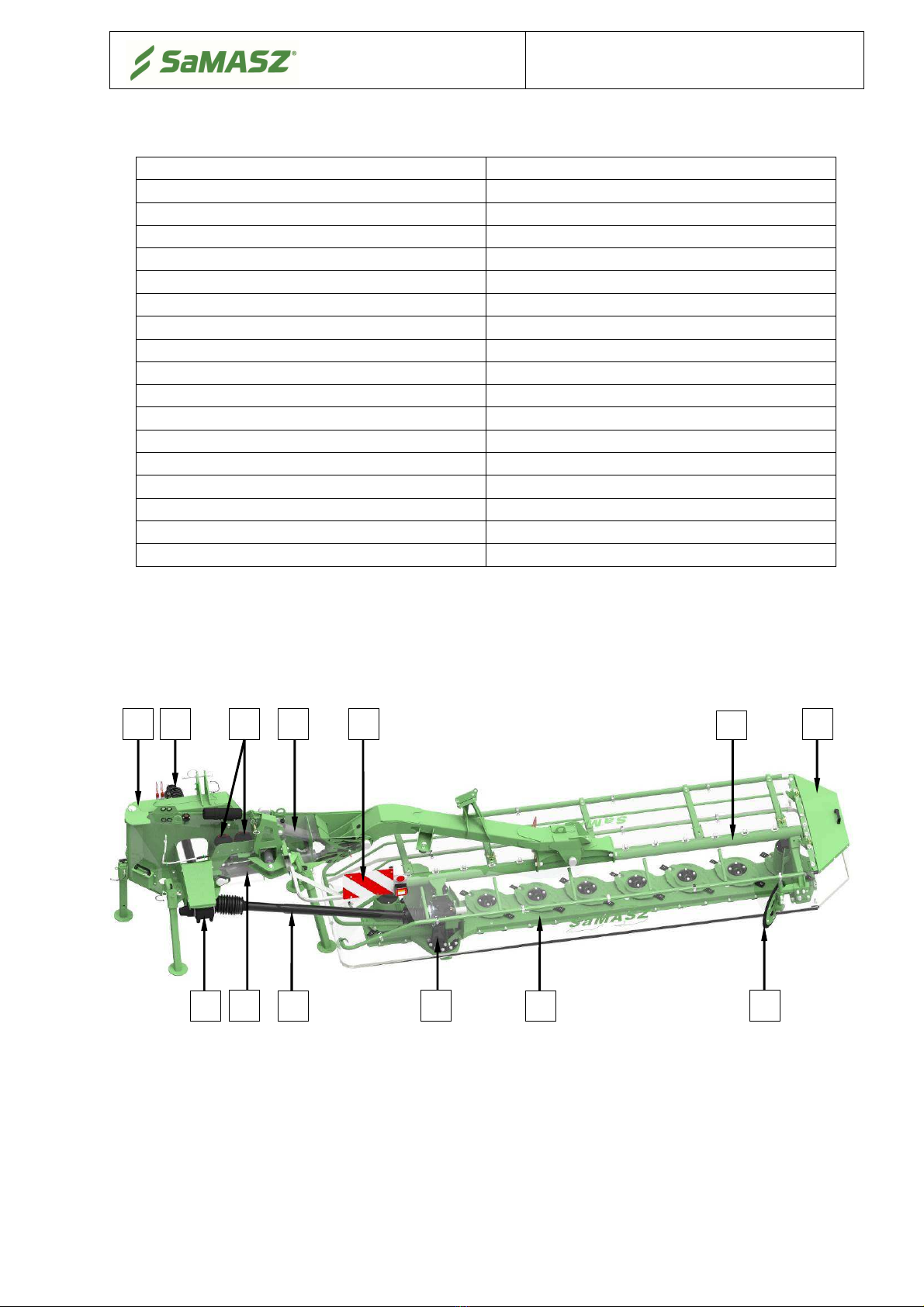
3.2. Design and working principle................................................................................................................5
3.3. Equipment and spare parts.....................................................................................................................6
4. SAFETY PRECAUTIONS .........................................................................................................................7
4.1. General safety rules and regulations......................................................................................................7
4.2. Qualifications of operator......................................................................................................................9
4.3. Conditions of mounting mower on tractor.............................................................................................9
4.4. Transport................................................................................................................................................9
4.4.1. Putting the mower onto another vehicle for transport....................................................................10
4.5. Working parts ......................................................................................................................................11
4.6. PTO shaft.............................................................................................................................................11
4.7. Hydraulic assembly .............................................................................................................................11
4.8. Safety curtains .....................................................................................................................................12
4.9. Residual risk ........................................................................................................................................12
4.9.1. Risk of machine entanglement .......................................................................................................12
4.9.2. Risk of injury, abrasion and damage of skin..................................................................................12
4.9.3. Risk of injury from liquid ejection out of hydraulic system ..........................................................12
4.9.4. Prohibited actions...........................................................................................................................13
4.9.5. Residual risk assessment ................................................................................................................13
4.10. Safety labels and their meaning ........................................................................................................13
4.11. Design and operations of hydraulic safety breakaway device ..........................................................16
5. USE OF MOWER .....................................................................................................................................16
5.1. Mounting mower on tractor.................................................................................................................17
5.1.1. Mounting PTO shaft ....................................................................................................................17
5.2. Control panel .......................................................................................................................................20
5.2.1. Setting hydro-pneumatic unloading of the mower.........................................................................20
5.2.2. Setting mower in position for driving on headlands and transport position...................................21
5.3. Preparing the mower for transport.......................................................................................................21
5.4. Preparing the mower for transport on public roads .............................................................................23
5.5. Changing the mower position from transport to operating position....................................................23
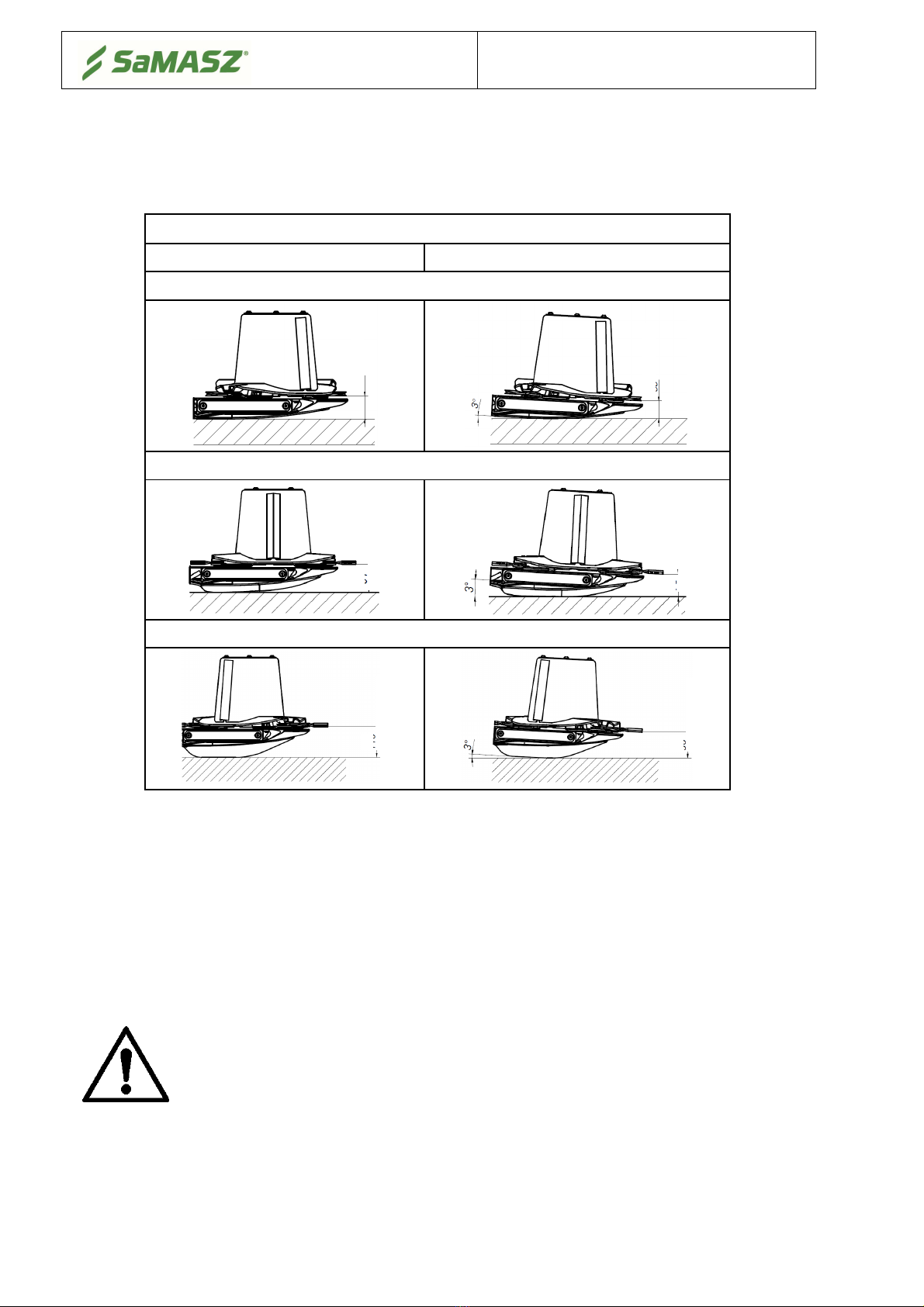
5.6. Preparing the mower for work.............................................................................................................24
5.7. Gas pressure in the accumulator and in the entire system ...................................................................25
6. OPERATING THE MOWER..................................................................................................................25
6.1. Taking turns over swaths.....................................................................................................................26
6.2. Removing clogging and jams ..............................................................................................................27
6.3. Dismounting machine from the tractor................................................................................................27
6.4. Storing machine...................................................................................................................................27
7. MOUNTING AND ADJUSTMENTS......................................................................................................28
7.1. Mounting knives..................................................................................................................................28
7.2. Checking condition of knives and holder pins ....................................................................................29
7.3. Replacing knives and holder pins........................................................................................................29
7.4. Swath width adjustment.......................................................................................................................31
7.5. Maintenance ........................................................................................................................................31
7.5.1. Daily maintenance .......................................................................................................................31
7.5.2. After -season maintenance and storing ........................................................................................32

Operator's manual
Rear disc mower with central suspension
XT 390
`
-
2
-
8. LUBRICATION ........................................................................................................................................33
8.1. Risks present when lubricating ............................................................................................................33
8.2. The cutterbar........................................................................................................................................33
8.3. Gear boxes ...........................................................................................................................................33
8.4. Lubrication points................................................................................................................................34
9. DEFECTS AND THEIR REPAIR...........................................................................................................35
10. REPAIR AND WITHDRAWAL FROM USE........................................................................................36
10.1. Repair ................................................................................................................................................36
10.2. Disassembly and withdrawal from use..............................................................................................36
11. ELECTRIC AND HYDRAULIC SCHEMES ........................................................................................37
12. WARRANTY CARD.................................................................................................................................39
13. WARRANTY TERMS..............................................................................................................................39
13.1. Warranty claims procedures..............................................................................................................39
13.2. Warranty repairs record.....................................................................................................................41
APPENDIX. DEFINING THE TOTAL WEIGHT, AXIS LOAD, TYRE LOAD CAPACITY AND
MINIMUM LOAD .........................................................................................................................................42

Operator's manual
Rear disc mower with central suspension
XT 390
`
-
3
-
1. IDENTIFYING THE MACHINE
Data plate (Fig. 2) is attached on the mower's main frame as shown below in Fig. 1.
Fig. 1.
Data plate
location
Fig. 2.
Data plate
Data plate includes:
name and adress of the manufacturer,
model year,
CE mar
kin
g
means, that the produce
conforms
to 2006/42/EC
version number,
Directi
ve and
harmonized standards,
machine weight,
machine symbol,
id number,
date of manufacture,
barcode.
NOTICE:
Should the contents of the herein manual be unclear, ask the manufacturer or your
dealer for more detailed information on the machine.
2. INTRODUCTION
This operator's manual should be considered the mower's basic equipment and should be kept for
further reference. If the mower is handed over to another user, it should be serviceable, and
include this operator's manual, CE declaration of conformity and its required basic equipment.
Before operating the mower its user must familiarize himself with this manual as well as current
work safety rules.
The mower is manufactured according to international safety rules.
Respecting recommendations herein shall ensure use safety.
Should you have any questions relating to the operation and service of the mower, please contact
the manufacturer.
This operator’s manual is an indispensable part of any machine and is intended to familiarize
future user with principles of proper operation and use of the machine as well as the risks
involved.
GENERAL PRECAUTION
When operating the machine always respect warnings and safety
rules marked with this sign.
WARNING!
Operating the mower without reading the contents of the manual, and by
unauthorized personnel, children in particular, is strictly forbidden.

Operator's manual
Rear disc mower with central suspension
XT 390
`
-
4
-
3. INTENDED USE
A mower XT is equipped with the „Perfect Cut” cutterbar. Tab. 1 shows the mowing height
differences, depending on the tilt angle of the cutterbar.
Tab. 1. Mowing height depending on the cutterbar type and its tilt angle
„Perfect Cut”
cutting bar
N
o tilt
3°
til
t
Standard mowing height
Optional heights when using high mowing topping
Optional heights when using high mowing double topping
NOTICE:
It is recommended to mow very rare grass with zero angle inclination.
The rear mounted disc mower is intended to mow green fodder: grass, alfalfa, etc. on permanent
grassland (pastures), crop fields without rocks, and to form loose rows of cut fodder. The pasture
or field being mown should be even, best if prepared by rolling. For the majority of tall grass the
first and second mowing should be done at height of 2.36″-2.75″(6-7cm), while for a majority
of short grasses at a height of 1.97″(5cm). The last mowing should be done a little higher - at
2.75″-3.15″(7-8cm) from the ground.
WARNING!
Do not use the mower for purposes other than those listed in this manual.
Otherwise it will be classified as misuse and could release the manufacturer
from responsibility for any damages. The mower should be used, serviced
and repaired only by personnel familiar with its characteristics and with
safety regulations. Tampering with the mower may release the manufacturer
from responsibility for any resulting malfunctions or damages.
72
mm /
2.83
''
9
1
mm /
3
.
58
''
70
mm /
2
.
76
''
110
mm /
4
.
33
''
54
mm /
2.
1
3
''
90
mm /
3
.
54
''

Operator's manual
Rear disc mower with central suspension
XT 390
`
-
5
-
3.1. Technical data
Tab. 2. General specification
Mower type XT 390
Mowing width [ft in / m] 12′9″/ 3.90
Number of blades [pcs] 18 (9x2)
Minimal cooperating tractor power 74 kW (100 HP)
Operating capacity at V = 12km/h ~ 4.5
Swath width [ft in / m] ~ 7′10″-8′8″/ 2.40 – 2.65
Transport width [ft in / m] ~ 8′6″/ 2.60
Working assembly width [ft in / m] ~ 20′/ 6.10
Transport length [ft in / m] ~ 5′1″/ 1.55
Machine height [ft in / m] ~ 12′4″/ 3.77
Weight [lbs / kg] 2866 / 1300
Tractor 3-point linkage category II/III
Tractor PTO speed [rpm] 1000
Line cutting speed [m/s] 88.4
Disc rotational speed [rpm] 3156
Emitted noise level [dB] L
pA
103 ± 1
L
Amax
109 ± 1
L
Cpeak
112 ± 1
L
pA
– noise level related to 8 hour working time. Averaged in time acoustic pressure level corrected by frequency
characteristic A.
L
Amax
– maximum value corrected by frequency characteristic A of acoustic pressure level.
L
Cpeak
– peak level of acoustic pressure corrected by frequency characteristic C.
3.2. Design and working principle
Fig. 3. Overview of rear disk mower
1
–
Suspension frame
8
–
Hydraulic cylinder
I
2
–
Main frame
9
–
Hydraulic cylinder
II
3
–
Cutterbar
10
–
Hydraulic accumulators
4
–
PTO shaft
I
11
–
Swath
guide
5
–
PTO shaft
II
12
–
Warning plate
s
and lights
6
–
Gearbox
I
13
–
Safety guard
7
–
Gearbox
II
2
7
1
8
9 12
13
6
5 3
10
11
4

Operator's manual
Rear disc mower with central suspension
XT 390
`
-
6
-
The suspension frame (1) allows the mower to be connected to the three-point hitch of
the tractor. Drive from tractor rpm is transmitted through PTO shaft I (4) and gearbox I (6) onto
PTO shaft II (5), which drives the cutterbar (3) through gearbox II (7). On the cutterbar (3) there are
discs with two cutting blades each. Extreme most discs are fitted with additionally mounted swath
guiding drums.
Hydraulic lifting cylinder I (8) and hydro-pneumatic suspension, fed from the tractor external
hydraulics and hydraulic accumulators (10) are used to adjust the mower to working position. Main
linkage frame (2), onto which cutterbar (3) is set features hydro-pneumatic cylinder II (9).
The abovementioned suspension enables the mower’s impact to the ground to be controlled oil
pressure adjustment in hydraulic cylinders.
The swath guide (11) and safety guard (13) are also installed on the main frame (2). A
standard equipment of the mower includes warning plate with combined lights and reflectors (12).
3.3. Equipment and spare parts
Mowers are sold with the following standard equipment:
warranty card,
operator's manual with spare part list and declaration of conformity,
cutting knives l=105 mm (4.13″): 2 sets (24 pcs.),
control panel,
knife mounting lever,
PTO shafts,
spray paint (0.5 fl oz / 150ml),
warning plates and lights.
Optional extra equipment:
warning triangle,
two swath cutterbar configuration,
high mowing toppings / double toppings,
working disc with instep.
NOTICE:
Optional extra equipment should be ordered separately.
Tab. 3. Recommended PTO shaft for connecting the mower to the tractor
Mower
Power
Length
Torque
Symbol Coupling
Manufacturer
HP
ft in / mm
Nm
XT 390
74 3′4″-4′7″/
1010
-
1417
520 7G5N101CE0071A1A
Unidirectional right
clutch
+
friction
Bondioli-
Pavesi
PTO shafts of other brands with equivalent technical parameters may be used on the SaMASZ
permission.
NOTICE:
Make sure to follow the PTO shaft lubrication frequency. Lubrication points marked
in Fig. 4 should be lubricated every 50 hours. Always lubricate the PTO shaft before
and after a period of longer idleness.

Operator's manual
Rear disc mower with central suspension
XT 390
`
-
7
-
Fig. 4. PTO shaft lubrication and direction of connection
4. SAFETY PRECAUTIONS
The following precautions are for your safety. They must be read carefully and
followed by every person who operates or maintains the machine. Failure to follow these safety
precautions could result in serious injury or death to the operator, maintenance person or bystanders
and property damage to the machine and surrounding property.
Safety Signal Words
This manual and the safety labels attached to this equipment utilize signal words that signify safety
hazards with different levels of severity. Below are the words used and the definitions for these
words:
DANGER indicates a hazardous situation which, if not avoided, will result in death or
serious injury
WARNING indicates a hazardous situation which, if not avoided, could result in death or
serious injury
CAUTION indicates a hazardous situation which, if not avoided, could result in minor or
moderate injury
NOTICE is used to address practices not related to physical injury
4.1. General safety rules and regulations
The following descriptions are for your safety: They must therefore be read
carefully and applied every time you use the machine.
Front axis of the tractor should be balanced to enable its steering. If necessary, use front wheel
weights.
In order to keep steering conditions, make sure that impact on the front axis is at least 20% of
the complete impact on the tractor.
Any operation with the hydraulic lift lever should be done from the operator's seat; never operate
the lever from outside of the tractor.
For tractors equipped with EHR, control with hydraulic lift is done with a button located outside
the tractor's cabin. When operating, please exercise particular caution.
When mounting the mower on a tractor, risk of wounding is likely. It is recommended that
operator wears protective gloves.
Do not operate without safety guards. Neither operation with damaged nor raised guard is
allowed (risk of stones, etc. being thrown out). Damaged safety curtain should be replaced.
Make sure to check condition of the guards and their mounting regularly.
PTO shaft end with unidirectional right
clutch + friction –
To be mounted on
the mower side
PTO shaft end without clutch –
To
be mounted on the tractor side

Operator's manual
Rear disc mower with central suspension
XT 390
`
-
8
-
Start mowing only when the tractor's PTO shaft reaches its nominal 1000 rpm.
Do not exceed 1050 rpm on the shaft.
Please make sure that no unauthorized personnel remains within the danger area of at least 170 ft
(50m). Keep particular caution when operating near roads and in stony areas.
Perform any maintenance and adjustment work only when the drive is disconnected and discs
have stopped completely.
Make sure to check condition of knife holders regularly. Replace any damaged or worn parts.
When driving on public roads always comply with local traffic regulations, especially on the
warning lights.
WARNING!
Make sure to perform any service and repair operations with the tractor drive
shut off and the cutterbar on the ground and after all rotating parts have
stopped completely.
WARNING!
Keep children away from the mower when operating and idle.
When the mower is lifted for repair on the 3-point linkage, it should be secured against falling by
a mechanical support or by chain.
Check bolts and other fasteners regularly. Do not operate with damaged or worn fasteners.
Do not leave a running tractor without supervision. Before leaving the tractor turn off the engine
and remove the ignition key.
If any break in the machine operation occurs, turn off the drive.
Tractor cooperating with the mower should be equipped with a driver's cabin.
Mower should not be operated when the tractor-mower aggregate is not well balanced.
Never start the mower in the lifted position.
Never start the mower if any people or animals are around the mower
Never lift the safety guard before rotating parts have come to a complete stop. Stop the tractor's
engine. Warning: Cutting knives keep rotating for several seconds after the engine has
been stopped.
Always follow safety decals describing hazards, and warning signs placed on the machine.
Before starting the tractor make sure that each drive is disconnected and control levers for
hydraulics are in neutral position.
Do not drive the mower backwards when operating.
Never get onto the mower.
Never lift the mower on tractor’s lift when the drive is on and discs are rotating.
For operation and transport do not drive slopes greater than 8°.
Never stand between the tractor and the mower, unless tractor-mower aggregate is protected
against moving with the tractor's parking brake.
Any inspections and adjustments may be conducted only when the mower is disconnected from
the tractor and on the ground.
For repairs or adjustments to be done under the mower make sure to secure it against falling
using a proper support.
If any part of the mower needs to be replaced, use only genuine spare parts according to spare
part list.
Pay particular attention to PTO shaft guards and mower and tractor spline shaft guards. Never
operate with damaged guards.
Inspect hydraulic hoses on regular basis and if any damage is found or their service life expires,
replace them. Service life for a hydraulic hose should be no longer than 5 years.
Never repair damaged hydraulic hoses using a tape.
When connecting hydraulic hoses to tractor’s hydraulic connectors make sure, that either tractor
or mower hydraulics are pressure free.

Operator's manual
Rear disc mower with central suspension
XT 390
`
-
9
-
When servicing hydraulic unit, always wear protective gloves and eyewear. Hydraulic oil
leaking under pressure (16MPa) may permeate through the skin and cause its infection
thereafter. If this is the case, immediately visit a doctor.
The mower should be stored under a roof and in such way so as to effectively prevent animals
and people from being injured.
Before starting the mower, make sure there are no animals underneath the guard.
Before operating the machine, make sure all safety devices are in place and working. If not
working or damaged replace them.
Before any maintenance, assembly, disassembly works and when parking position the machine
on a solid ground and secure it against accidental movements.
When cleaning the machine, use personal protective equipment for health protection.
Do not leave agricultural machinery on slopes or other descents without providing protection
against free runaway.
When operating on a stony field or nearby roads there is a risk of throwing out stones or other
objects which may pose a danger for passing-by vehicles on the road or for passers-by.
Therefore keep the safe distance.
If any break in the equipment operation occurs, turn off the drive. Before leaving the tractor turn
off the engine and remove the ignition key, leave the cabin and make sure there are no
unauthorized personnel in the cabin and close the door.
The operator is not allowed to leave the tractor while driving.
In case of a major failure, stop the machine's drive, turn off the tractor's engine and remove the
ignition key. Next, please contact technical service, and if accident (i.e.: road accident) occurs,
respect first aid rules and call appropriate authorities.
Keep the mower clean, so as to avoid a risk of fire.
4.2. Qualifications of operator
To provide safe machine operation each person being the machine operator must meet the
following requirements:
Operator should hold driving license, have ability to drive vehicles safely and know road traffic
rules.
Operator must be in proper physical condition to be able to operate the machine.
Operator must not be under the influence of alcohol, drugs and medicines, which all have
influence on vehicle driving and machine operation.
Operator should be familiarized with this manual and follow its provisions.
Operator should be familiar with working principles of both the tractor and the machine, and be
able to recognize and avoid hazards resulting from operation of the aggregate.
4.3. Conditions of mounting mower on tractor
Before the mounting operation, check whether the tractor's and the mower's hitch categories are
compatible and make sure that tractor's hitch load is adequate for the machine aggregated.
Before mounting the machine, inspect technical condition of the mower's hitch assembly and
tractor's 3-point linkage.
Use only genuine pins and cotters to mount the mower on a tractor.
4.4. Transport
Front axis of the tractor should be well balanced to allow for its steering. If necessary, use front
wheel weights.
Any modifications in the mower's position are possible only if no unauthorized personnel is
around (children in particular).
For transport make sure that the mower has portable light board and the triangular safety sign
identifying a slow moving vehicle mounted.
When transporting the mower make sure it is always placed in the transporting position.
Before moving the mower to transport position make sure, that the tractor’s PTO is turned off
and all rotating parts have come to a complete stop.
Always adjust driving speed to current road conditions and local traffic code.

Operator's manual
Rear disc mower with central suspension
XT 390
`
-
10
-
Do not exceed a permissible speed of 15mph (25km/h).
Do not transport any people or objects on the machine.
When taking turns pay particular attention and keep in mind the machine's weight and
dimensions.
Bear in mind that when operating and transporting the machine in areas where high voltage lines
are present, exercise special caution as it is likely for the aggregate to touch the lines.
It is forbidden for the operator to leave the vehicles when driving.
Reckless driving and speeding may cause a traffic accident or collision.
4.4.1. Putting the mower onto another vehicle for transport
The driver and the carrier are responsible for mower’s transport safety. Equipment and parts
must be secured during transport.
To put the mower onto another vehicle in a safe way, please follow the procedure below:
Grab the machine by any lifting devices only in places indicated by hook sign (Fig. 5),
Fig. 5. Transport holders
For hoisting do use hoists with capacity bigger than the machine weight as indicated on its data
plate. It also applies to the necessary cables and chains,
Transport belts, belt suspensions, ropes cannot be damaged. Whenever damages to these parts
are found, replace them,
When mounting slings, chains, clamps, etc. always keep in mind the center of gravity of the
machine (Tab. 4),
For seizing the machines pick lines of adequate length, so that the angle between them was no
greater than 120°, and the angle of inclination between the cable and the vertical was no greater
than 60°,
Collapsible parts should be blocked in transport position,
When relocating the mower onto another vehicle, there should be no unauthorized personnel
permitted to remain within the danger area,
The mower should be protected against moving on the vehicle's trailer.
WARNING!
Securing the maneuver area and providing safety for operation performed is
the responsibility of the person in charge of the plow moving.

Operator's manual
Rear disc mower with central suspension
XT 390
`
-
11
-
Fig. 6. Location of center of gravity
Tab. 4. Location of center of gravity
Dimension
[ft in / mm]
Mower type
XT 390
A 8′3″/ 2520
B 11′6″/ 3500
C 2′1½″/ 650
D 2′3½″/ 700
E 2′7½″/ 800
F 1′7″/ 480
4.5. Working parts
Before operating the mower check condition of the knife, knife mountings and the knife holders.
Immediately Replace any worn or damaged knives, knife mountings or knife holders.
During replacement of working parts, it should be used personal protective gloves.
4.6. PTO shaft
Before operating learn provisions found in the shaft manufacturer's manual placed on the shaft.
Use only the mower's manufacturer recommended PTO shafts with guards in good technical
condition.
In order to operate safely use only fully serviceable, undamaged PTO shafts. Repair o replace a
damaged PTO shaft.
Before any operation make sure whether PTO rpm have proper rotational direction.
4.7. Hydraulic assembly
WARNING! Hydraulic assembly is under pressure! Hydraulic oil under pressure may permeate
through skin and cause serious injury, therefore protect skin and eyes. In case of injuries caused
by a liquid under pressure, call doctor immediately.
Hydraulic hoses can be connected to tractor's hydraulics, only if both the tractor’s and the
mower's hydraulic assemblies are not under pressure. To remove the pressure from hoses just
simply restart the tractor's hydraulic valves several times, after the tractor’s drive is turned off.
When dismounting the machine from the tractor, set the equipment aside, deflate the pressure
from hydraulics and turn off the tractor's engine.
When inspecting for hydraulic assembly's malfunction and looking for oil leaks, do not touch
any potential leaks until the entire assembly is under pressure.
It is recommended that the used hydraulic oil should not exceed 10 oil purity class in
accordance with NAS 1638.
When using hydraulic hoses:
Avoid stretching the hoses when operating.
Do not allow hydraulic hoses to get deflected.
Do not expose hydraulic hoses to contact with any sharp edges.
If damaged or worn, replace the hoses.
Service life for hydraulic hoses is 5 years from their production date.

Operator's manual
Rear disc mower with central suspension
XT 390
`
-
12
-
4.8. Safety curtains
For storage, the SaMASZ manufactured mowers have standard safety curtains (1) to be
mounted on user’s own. In order to mount the curtain properly put it on mower and secure using
catches (2) and with front guard (3) (Fig. 7). Front guard (3) should be fixed so that it holds the
safety curtain (1). Examine condition of guards and its mounting on regular basis.
Fig. 7. Mounting safety curtain on mower
4.9. Residual risk
Despite the fact, that SaMASZ Sp. z o.o. company –the manufacturer of the mower takes the
responsibility for the mower design and manufacturing, in order to eliminate hazard, certain risk
when operating the mower is unavoidable.
Major source of risk results from the following operations:
operation of mower by minors and operators not being familiarized with operator's manual,
operation of mower by personnel under influence of alcohol or other abusive substances,
failure to keep caution while transporting and moving the mower during operation,
transport of personnel on the machine,
presence of persons and animals within the mower operating range,
service and adjustment operations with engine running.
4.9.1. Risk of machine entanglement
This risk occurs when (1) changing position of a mower, (2) operating near rotating parts, and
(3) working without safety guards. During operation, maintenance and adjustment, always wear
protective gloves, shoes and clothes without loose parts, belts and so on. Always comply with safety
labels placed on the mower.
4.9.2. Risk of injury, abrasion and damage of skin
This risk occurs during replacement of working parts with sharp edges, cleaning the machine
and removal of any clogging and jams. During any maintenance work, always use safety gloves.
4.9.3. Risk of injury from liquid ejection out of hydraulic system
When connecting and disconnecting hydraulic hoses to and from the tractor’s hydraulic
connectors make sure, that both tractor or mower hydraulics are pressure free.
When servicing hydraulic unit, always wear protective gloves and eyewear. Inspect hydraulic
hoses regularly.
WARNING!
Present residual risk results mainly from erroneous actions of the mower’s
operator and failure to follow the instruction manual.
2
1
3

Operator's manual
Rear disc mower with central suspension
XT 390
`
-
13
-
4.9.4. Prohibited actions
Bear in mind the following prohibited actions when operating the mower:
Do not unblock the mower, make any adjustments or repairs when the mower is operating,
Never change the sequence of operation and maintenance works specified in the operator's
manual,
Never operate the mower when its working condition is poor or its safety guards are damaged,
Never get your limbs close to mower's rotating parts,
During repair and maintenance works on the mower always comply with the descriptions
included in the operator's manual, while making sure the tractor’s drive is turned off,
Before any works, focus your attention solely on the tasks to do,
Never operate the mower being under influence of alcohol, drugs, or strong medicines,
Wear clothing that is not too loose, or too tight. Too loose clothing elements may be pulled in by
the mower's rotating parts,
Make sure the mower is not operated by children no handicapped people.
When describing residual risk, the mower shall be considered a machine, which until the
moment of production launching had been designed and manufactured in accordance with the state
of the art at the day of the manufacture.
WARNING!
Despite following the specified instructions and prohibitions, residual risk is
still present.
4.9.5. Residual risk assessment
read operator’s manual thoroughly,
make sure no person remains on the machine when operating and driving,
make sure no person remains within the mower's operating range,
before any adjustment, maintenance and lubrication works on the machine, make sure its engine
is turned off,
repair works on the machine can be done by properly qualified and skilled personnel only,
before operating the machine, carefully read the operator’s manual,
make sure that no children and unauthorized personnel stays around the machine.
When the risk of being exposed to noise cannot be avoided or eliminated by any
group protective equipment or through organization of work, employer (operator)
must:
1) provide the operator with individual noise protection equipment, if noise level in
work place exceeds 80 dB.
2) provide the operator with individual noise protection equipment and supervise its
proper use, if noise level in work place reaches or exceeds 85 dB.
4.10. Safety labels and their meaning
Safety labels are critical to safe use of this mower. They must be read, understood and followed.
Also, be sure that:
All warning decals are clean and legible
All lost or damaged decals are replaced by ordering new decals from your dealer or supplier
All persons using this mower have read the section of this manual explaining the meanings of
these labels
All spare part used for repair of the mower should have all safety labels provided by the
manufacturer.

Operator's manual
Rear disc mower with central suspension
XT 390
`
-
14
-
N-01
Be extremely careful when
PTO shaft is rotating
N-02
Warning: cutting knives!
Do not get near to the
operating mower
N-03
Prior to operation
commencement read the
operator's manual carefully
N-04
Prior to approaching any
maintenance or repair
works, turn the machine off
N-06
Warning: pulling-in
parts
N-07
Operating the mower is
forbidden with presence
of any unauthorized
personnel within the
danger area of 170 ft./
50 m
N-11
Lubrication point
N
-
14
N
-
15
N-23
Warning: power lines
N-28 N-40
Transport holder for moving
the mower
N-48
Stay away from mower’s
inclination area
N-49
Do not get too close to
the hoist of the tractor
during operation of the
hoist
N-50
Do not remain in the
mower swinging area
N-55

Operator's manual
Rear disc mower with central suspension
XT 390
`
-
15
-
N-28 N-40
N-11
N-40
N-01; N-02; N-03; N-04
N-06; N-07; N-23; N-48
N-49; N-50; N-117
N-167; N-168; N-224
N-14; N-15; N-63; N-162
N-204; N-205; N-206
N
-
63
N
-
109
N-117
Avoid contact with liquid
coming out under pressure
N-167
Do not remain on the
machine while driving
N-162
N-168
Do not touch the machine
before the rotating parts
have not come to a
complete standstill
N-204
Use the required Personal
Protective
N-205
Use the required Personal
Protective
N-206
Use the required Personal
Protective
N-224
Do not open and remove
safety guards with motor
operating
Fig. 8. Safety labels placed on the mower

Operator's manual
Rear disc mower with central suspension
XT 390
`
-
16
-
NOTICE:
Any spare part used for repair of the mower should have all warning decals provided
by the manufacturer.
4.11. Design and operations of hydraulic safety breakaway device
Hydraulic safety breakaway device (Fig. 9) protects mower from hitting small obstacles.
When an obstacle is hit, the cutting unit retracts by 15° enabling retraction of the first disc by more
than 1′8″(0.5m) back, while lifting the first disk by more than 1′1″(0.3m) up. After that, the
cutterbar automatically comes back to its working position.
Fig. 9. Hydraulic safety breakaway device
Fig. 10. Mower held back up and backwards after safety breakaway advice is used
WARNING!
Proper operation of hydraulic safety breakaway device is ensured only if
factory-set value (1102 lbs / 500 kg) is maintained. Any change in safety
breakaway device adjustments will render warranty null and void.
5. USE OF MOWER
WARNING!
Before beginning to use this machine, do the following:
Read manual, especially safety precautions in section 4.
Make sure you are familiar with all controls and functions.
Make sure all safety devices are in place and working. Fix or replace if not
working or damaged.
Replace protective cover if damaged.

Operator's manual
Rear disc mower with central suspension
XT 390
`
-
17
-
5.1. Mounting mower on tractor
WARNING!
Only hitch and unhitch machine on a flat surface with compact dirt.
Keep everyone away from area between mower and tractor.
Be careful near link road zone of tractor's rear power lift. Contains sharp
parts.
Any accidental maneuvering with the set may cause to crushing of
unauthorized personnel.
Mount the machine on a level ground.
The mower is suitable for mounting on tractors with three-point linkage cat. II and III (Fig. 11).
After the mower has been mounted, adjust (on a level ground) the mower’s position by means
of top (C) and lower links (W). The cutterbar should lean (~3°) towards the driving direction. Lower
links (W) should be connected to 3-point linkage frame pins (S).
Then connect:
hydraulic hose to tractor’s floating section,
PTO shaft (B) to tractor (p. 5.1.1),
the machine's lighting cables (A) to the tractor’ electric socket,
control panel (Fig. 16)using hermetic connector (place the panel in the tractor).
Fig. 11. Mounting mower on tractor
After the mower has been mounted on the tractor, check the balance and whether the tractor-
mower aggregate is steerable. To do this, calculate to formulas given in the appendix or weigh the
aggregate, and then drive on the scales only with front axis of the tractor (the mower must be in
transport position – lifted upwards). If the pressure on the front axis is at least 20% of the whole
aggregate’s weight, it means the aggregate is stable. Otherwise the front axis should be balanced.
5.1.1. Mounting PTO shaft
Before operation, check and adjust length of PTO shaft, which is designed for mounting the
machine on a tractor. In some cases it is possible, that the shaft is too long and therefore needs to be
shortened, so that there is adequate tolerance for the shortest possible distance between tractor’s
shaft (A) and machine’s shaft (B).
The cover should be secured so that it does not spin by securing the holding chains to
a permanent part of the body of the tractor and the loop on the guard of the splined shaft of
the mower drive shaft. Shaft's length should be adjusted individually for the tractor, on which the
machine is mounted.
B
W
S
C
A

Operator's manual
Rear disc mower with central suspension
XT 390
`
-
18
-
In order to determine minimal shaft length:
set aggregated mower in working position,
take measurement of distance between two shafts as provided in Fig. 12 - Fig. 13,
additionally distract 3.15″(80mm) from the resulting measurement (L
Z
)
in order to keep
tolerance and shorten the shaft for this particular length (Fig. 14). Information on proper
shortening of shafts is provided on label N-149 (Fig. 15) placed on the machine and also in
shaft’s manual delivered by its manufacturer.
Fig. 12. Distance between tractor’s PTO shaft and machine’s drive shaft
Fig. 13. Properly measured length
As a result, length of PTO shaft is obtained, and then the shaft can be used safely to mount the
machine on the tractor.
Fig. 14. Properly measured shaft length
L
M
= L
Z
– 3.15″(80mm)
NOTICE:
If necessary, shorten the PTO shaft according to its operator’s manual given by the
shaft’s manufacturer (Fig. 15).
WARNING!
When changing the tractor, with which the machine operates, check the
length of PTO shaft again, as otherwise the machine can be damaged.
L
M
- Shaft length
L
Z
- measured length
B
A
Other manuals for XT 390
1
Table of contents
Other SaMASZ Lawn Mower manuals

SaMASZ
SaMASZ KDC 260 User manual

SaMASZ
SaMASZ KT 261 User manual

SaMASZ
SaMASZ K2BF 210 User manual

SaMASZ
SaMASZ SAMBA 240 User manual

SaMASZ
SaMASZ TORO 260 User manual

SaMASZ
SaMASZ KBRP 160 User manual

SaMASZ
SaMASZ KBRP 160 User manual

SaMASZ
SaMASZ KDF 260 User manual

SaMASZ
SaMASZ Z 010 User manual

SaMASZ
SaMASZ KDF 260 User manual

SaMASZ
SaMASZ KDD 860 User manual

SaMASZ
SaMASZ MIDO 140 User manual

SaMASZ
SaMASZ KDC 300 W User manual

SaMASZ
SaMASZ KBRP 160 User manual

SaMASZ
SaMASZ KDF 390 User manual

SaMASZ
SaMASZ KWT 550 User manual

SaMASZ
SaMASZ KDF 260 User manual

SaMASZ
SaMASZ KDD 861 User manual

SaMASZ
SaMASZ KDF 390 User manual

SaMASZ
SaMASZ KDT 180 User manual