SAMCHULLY RHB-250 User manual

NC Rotary Table
Horizontal Built-in type
Instruction Manual
RHB-250
RHB-400
본체취급설명서 1
Please read the DANGER and Warning sections
before operating the NC Rotary Table.
Please keep this manual handy as it may answers to
any questions you may have.
NC 로터리 테이블을 조작하기 전에 이 설명서의
위험/경고항목을 잘 읽고 숙지해 주십시오.
이 설명서를 궁금한 사항이나 점검할 사항 등
필요할 때 참조할 수 있도록 잘 보관하십시오.
IMPORTANT
중요

2NC Rotary Table

3
Instruction Manual
머리말 Precautions
안전하게 사용하기 위해서 필요한 경고사항을 본서에 기재했으니, 반드시 읽
어 주십시오. 문장 중의 마크는 특히 주의하여 주십시오. 산업용 기계
이므로 사용자 또는 이 장비를 사용하는 다른 사람에게 위험할 수 있는 항목
이나 조작에는 “안전 경고 기호” 를 사용하여 사용자의 주의를 환기시킵니
다. 안전 경고 기호로 표시한 지침을 잘 읽고 반드시 준수해 주십시오.
안전 경고 기호 Warning symbol
삼천리기계의 제품을 사용해 주셔서 진심으로 감사 드립니다.
본 취급설명서에 따라 제품의 사용방법을 바르게 이해하시고, 귀사의 생산에
기여할 수 있도록 활용하여 주십시오.
또한, 알아두면 편리한 제품의 성능 등에 관하여 유의사항으로 설명해 두었
습니다. 본 취급설명서는 분실되지 않도록 항상 제품 가까이에 보관하여 주
십시오.
!
Thank you so much for choosing Samchully. Please read this manual
carefully and fully understand the procedures for installation, operation,
inspection and maintenance before operating the product.
Keep this manual handy as it contains detailed information on product
functionality.
To ensure safe operation, please read this instruction manual and pay
particular attention to the symbol which emphasizes important
information.
!
경고 용어 Warning term
!DANGER
위 험
적절한 안전 절차와 지침을 준수하지 않으면 사망에
이르거나 중상을 입게 되는 매우 위험한상황을 나타
냅니다.
!WARNING
경 고
적절한 안전 절차와 지침을 준수하지 않으면 사망에 이
르거나 중상을 입을 수 있는 잠재적으로위험한 상황을
나타냅니다.
!CAUTION
주 의
적절한 안전 절차와 지침을 준수하지 않으면 가벼운 상
처나 부상을 입을 가능성이 있는 잠재적으로 위험한 상
황을 나타냅니다.
IMPORTANT
유의사항
제품의 성능 및 오류나 실수를 막기 위한 지침입니다.
!DANGER
!WARNING
!CAUTION
IMPORTANT
Indicates an imminently hazardous situation which,
if not avoided, will result in death or serious injury.
These warning messages include the preventive
actions that are indispensable to avoiding danger.
Indicates a potentially hazardous situation which,
if not avoided, will result in death or serious injury.
These warning messages include the preventive
actions that are indispensable to avoiding danger.
Indicates a potentially hazardous situation which,
if not avoided, could result in minor injury or
machine damage.
Instructions for optimal performance and avoiding
errors or mistakes.

4NC Rotary Table
1. 사용 및 안전을 위하여 ‥‥‥‥‥‥‥‥‥‥‥‥‥‥‥‥‥‥‥‥‥‥‥‥ 6
2. 사양 ‥‥‥‥‥‥‥‥‥‥‥‥‥‥‥‥‥‥‥‥‥‥‥‥‥‥‥‥‥‥‥‥ 10
3. 정밀도 ‥‥‥‥‥‥‥‥‥‥‥‥‥‥‥‥‥‥‥‥‥‥‥‥‥‥‥‥‥‥‥ 11
4. 운전준비 ‥‥‥‥‥‥‥‥‥‥‥‥‥‥‥‥‥‥‥‥‥‥‥‥‥‥‥‥‥‥ 12
4-1.설치 ‥‥‥‥‥‥‥‥‥‥‥‥‥‥‥‥‥‥‥‥‥‥‥‥‥‥‥‥‥‥‥‥‥‥ 12
4.1.1.운반과공작기계의장착‥‥‥‥‥‥‥‥‥‥‥‥‥‥‥‥‥‥‥‥‥‥‥‥‥‥ 12
4-2.윤활 ‥‥‥‥‥‥‥‥‥‥‥‥‥‥‥‥‥‥‥‥‥‥‥‥‥‥‥‥‥‥‥‥‥‥ 13
4-3.클램프시스템‥‥‥‥‥‥‥‥‥‥‥‥‥‥‥‥‥‥‥‥‥‥‥‥‥‥‥‥‥‥ 14
4.3.1.유압클램프시스템 ‥‥‥‥‥‥‥‥‥‥‥‥‥‥‥‥‥‥‥‥‥‥‥‥‥‥‥‥ 14
4-4.에어퍼지에관하여‥‥‥‥‥‥‥‥‥‥‥‥‥‥‥‥‥‥‥‥‥‥‥‥‥‥‥‥ 15
4-5.공작물의설치‥‥‥‥‥‥‥‥‥‥‥‥‥‥‥‥‥‥‥‥‥‥‥‥‥‥‥‥‥‥ 15
5. 점검작업 ‥‥‥‥‥‥‥‥‥‥‥‥‥‥‥‥‥‥‥‥‥‥‥‥‥‥‥‥‥‥ 16
5-1.일일점검 ‥‥‥‥‥‥‥‥‥‥‥‥‥‥‥‥‥‥‥‥‥‥‥‥‥‥‥‥‥‥‥‥ 16
5-2.정기점검 ‥‥‥‥‥‥‥‥‥‥‥‥‥‥‥‥‥‥‥‥‥‥‥‥‥‥‥‥‥‥‥‥ 16
6. 로터리테이블 클램프의 설명 ‥‥‥‥‥‥‥‥‥‥‥‥‥‥‥‥‥‥‥‥‥ 16
6-1.로터리테이블클램프의주의사항 ‥‥‥‥‥‥‥‥‥‥‥‥‥‥‥‥‥‥‥‥‥ 16
6-2.클램프·언클램프확인장치‥‥‥‥‥‥‥‥‥‥‥‥‥‥‥‥‥‥‥‥‥‥‥‥ 17
6-3.클램프·언클램프용압력센서‥‥‥‥‥‥‥‥‥‥‥‥‥‥‥‥‥‥‥‥‥‥‥ 17
7. 구성품 설명 및 유지보수, 조정 ‥‥‥‥‥‥‥‥‥‥‥‥‥‥‥‥‥‥‥‥ 18
7-1.웜기어의백래시조정‥‥‥‥‥‥‥‥‥‥‥‥‥‥‥‥‥‥‥‥‥‥‥‥‥‥‥ 18
7.1.1.웜기어의백래시측정방법 ‥‥‥‥‥‥‥‥‥‥‥‥‥‥‥‥‥‥‥‥‥‥‥‥‥ 18
7.1.2.웜기어의백래시조정방법 ‥‥‥‥‥‥‥‥‥‥‥‥‥‥‥‥‥‥‥‥‥‥‥‥‥ 19
7-2.모터(Motor)교환시커버(Cover)탈착방법‥‥‥‥‥‥‥‥‥‥‥‥‥‥‥‥‥ 22
7.2.1.방수대책‥‥‥‥‥‥‥‥‥‥‥‥‥‥‥‥‥‥‥‥‥‥‥‥‥‥‥‥‥‥‥‥‥ 22
8. 보관 ‥‥‥‥‥‥‥‥‥‥‥‥‥‥‥‥‥‥‥‥‥‥‥‥‥‥‥‥‥‥‥‥ 23
9. 참고자료 ‥‥‥‥‥‥‥‥‥‥‥‥‥‥‥‥‥‥‥‥‥‥‥‥‥‥‥‥‥‥ 24
9-1.원호길이와각도의환산 ‥‥‥‥‥‥‥‥‥‥‥‥‥‥‥‥‥‥‥‥‥‥‥‥‥ 24
목차

5
Instruction Manual
1. For Safe Operation ‥‥‥‥‥‥‥‥‥‥‥‥‥‥‥‥‥‥‥‥‥‥‥‥‥ 6
2. Specifications ‥‥‥‥‥‥‥‥‥‥‥‥‥‥‥‥‥‥‥‥‥‥‥‥‥‥‥ 10
3. Accuracy ‥‥‥‥‥‥‥‥‥‥‥‥‥‥‥‥‥‥‥‥‥‥‥‥‥‥‥‥‥‥ 11
4. Preparations for Operation ‥‥‥‥‥‥‥‥‥‥‥‥‥‥‥‥‥‥‥‥‥ 12
4-1.Installation ‥‥‥‥‥‥‥‥‥‥‥‥‥‥‥‥‥‥‥‥‥‥‥‥‥‥‥‥‥‥‥ 12
4.1.1.Transportation,andInstallationontheMachineTool‥‥‥‥‥‥‥‥‥‥‥‥‥‥ 12
4-2.Lubrication ‥‥‥‥‥‥‥‥‥‥‥‥‥‥‥‥‥‥‥‥‥‥‥‥‥‥‥‥‥‥‥ 13
4-3.ClampSystem ‥‥‥‥‥‥‥‥‥‥‥‥‥‥‥‥‥‥‥‥‥‥‥‥‥‥‥‥‥ 14
4.3.1.HYD.ClampSystem‥‥‥‥‥‥‥‥‥‥‥‥‥‥‥‥‥‥‥‥‥‥‥‥‥‥‥‥‥ 14
4-4.AbouttheAirPurgeSystem‥‥‥‥‥‥‥‥‥‥‥‥‥‥‥‥‥‥‥‥‥‥‥ 15
4-5.MountingaWorkpiece ‥‥‥‥‥‥‥‥‥‥‥‥‥‥‥‥‥‥‥‥‥‥‥‥‥ 15
5. Inspection ‥‥‥‥‥‥‥‥‥‥‥‥‥‥‥‥‥‥‥‥‥‥‥‥‥‥‥‥‥ 16
5-1.DailyInspection‥‥‥‥‥‥‥‥‥‥‥‥‥‥‥‥‥‥‥‥‥‥‥‥‥‥‥‥‥ 16
5-2.PeriodicInspection ‥‥‥‥‥‥‥‥‥‥‥‥‥‥‥‥‥‥‥‥‥‥‥‥‥‥‥ 16
6. Description of the NC Rotary Table ‥‥‥‥‥‥‥‥‥‥‥‥‥‥‥‥‥ 16
6-1.CautionsfortheTableClamp ‥‥‥‥‥‥‥‥‥‥‥‥‥‥‥‥‥‥‥‥‥‥ 16
6-2.Clamp,UnclampCheckDevice ‥‥‥‥‥‥‥‥‥‥‥‥‥‥‥‥‥‥‥‥‥ 17
6-3.Clamp/UnclampPressuresensor ‥‥‥‥‥‥‥‥‥‥‥‥‥‥‥‥‥‥‥‥ 17
7. Description, maintenance and adjustment of components ‥‥‥‥‥‥ 18
7-1.Adjustingbacklashofwormgear ‥‥‥‥‥‥‥‥‥‥‥‥‥‥‥‥‥‥‥‥ 18
7.1.1.MethodofMeasuringWormGearBacklash‥‥‥‥‥‥‥‥‥‥‥‥‥‥‥‥‥‥ 18
7.1.2.HowtoAdjusttheBacklashoftheWormgear ‥‥‥‥‥‥‥‥‥‥‥‥‥‥‥‥ 19
7-2.Removalandinstallationofcoverforreplacingthemotor‥‥‥‥‥‥‥‥‥ 22
7.2.1.WaterproofingMeasures ‥‥‥‥‥‥‥‥‥‥‥‥‥‥‥‥‥‥‥‥‥‥‥‥‥‥ 22
8. Storage ‥‥‥‥‥‥‥‥‥‥‥‥‥‥‥‥‥‥‥‥‥‥‥‥‥‥‥‥‥‥ 23
9. References ‥‥‥‥‥‥‥‥‥‥‥‥‥‥‥‥‥‥‥‥‥‥‥‥‥‥‥‥‥ 24
9-1.ConversionbetweenArcLengthandAngle ‥‥‥‥‥‥‥‥‥‥‥‥‥‥‥ 24
TABLEOFCONTENTS

6NC Rotary Table
1. 사용 및 안전을 위하여 1. For safe operation
사용 전에 알아두셔야 할 것, 지켜야 할 것을 정리해 놓았습니다. 반드시 읽
어주십시오. 당사는 이 취급설명서에 따르지 않은 경우에 발생하는 불량, 사
고에 관한 책임은 지지 않습니다.
Please read this manual before operating the chuck and follow the direc-
tions. Samchully does not assume responsibility for accidents resulting
from a failure to follow the guidelines in this manual.
!DANGER
위 험 !DANGER
NC 로터리 테이블의 설치, 보수점검, 수리 시에는
반드시 설치기계 및 컨트롤러의 전원을 끄십시오.
몸의 일부나 의복이 말려들어가 부상당하는 위험이 있습니다.
Switch power off the machinery and the controllers
for installation prior to start installation,
maintenance or repair of the tilting NC rotary table.
Loose clothing or limbs may get caught during operation.
클램프 볼트는 정확한 토크로 고정하십시오.
테이블 회전시 회전영역 구간에 손을 넣지 마십시오.
클램프 볼트의 과도한 체결은 바디에 변형이 올 수 있으므로 정확한 토크로 조이십시오.
회전 중에 신체일부가 끼일 위험이 있습니다.
Tighten the bolts with correct torque.
Keep hands away from rotary table while it is rotating.
Applying excessive torque will deform the product or the bolts themselves.
Injury may result from a limb getting caught.
육각볼트 사이즈 조임토크(N^m)
M10 33.8
M12 58.9
M16 146.3
M20 294.3
!WARNING
경 고
!WARNING
ON
OFF
ON
OFF
OFF
OFF

7
Instruction Manual
!WARNING
경 고
!WARNING
NC 로터리 테이블을 개조하거나 임의로 수정하지 마십시오.
NC 로터리 테이블이 파손되고 공작물이 비산할 위험이 있습니다.
Never modify or the tilting NC rotary table without
approval from Samchully.
Damage may occur.
허용치 이상의 절삭력을 가하지 마십시오.
NC 로터리 테이블이 파손되고 공작물이 비산할 위험이 있습니다.
Do not exceed the allowable cutting force.
Product may be damaged and/or work may be thrown.
NC로터리테이블과 설치기계와의 간섭에 유의하십시오.
공구 등이 파손되고 비산할 위험이 있으며 케이블 호스는 설치기계와의
간섭 및 현저한 굴곡을 피하십시오. 케이블이 손상되면 감전의 위험이 있습니다.
Be cautious of any interference.
Interference may result in damage to tools and machine.
Please avoid excessive coiling of cables.
F
NO!
모든 커버류 설치면에 기밀유지를 위하여 O링이 설치되어 있습니다.
(커버 분해 시 O링을 손상시키지 않을 것)
O-rings are installed under all covers for air-tightness.
(Pay special attention to protecting the O-rings from damage when
disassembling the covers.)
O-RING
O-RING
O-RING

8NC Rotary Table
!CAUTION
주 의 !CAUTION
6개월마다 윤활유를 교환하여 주십시오.
(사용조건에 따라 주기는 변경될 수 있습니다.)
가공물의 설치, 해체는 테이블을 클램프 한 후 실행하십시오.
정밀도 저하 뿐만 아니라 NC 로터리 테이블이 파손되고 공작물이 비산할 위험이 있습니다.
Change the lubricant every six months.
(Actual change-cycles may vary depending on use)
Clamp the NC rotary table prior to installing and
dismantling workpieces.
Loss of precision and damage may occur.
NC 로터리 테이블의 각 부분에 충격을 주지 마십시오.
NC 로터리 테이블이 파손되고 공작물이 비산할 위험이 있습니다.
Do not apply impact to any part of the rotary table.
Do not cause subject any part of the NC Rotary Table to shock or impact.
← Air Purge
NO!
NC 로터리 테이블을 운반할 때는 아이볼트 및
와이어로프를 사용하십시오.
낙하할 위험이 있습니다.
Use eyebolts and wireropes when moving
the NC rotary table.
Dropping the rotary table will cause damage and possibly injury.
와이어로프 / Wire rope
아이볼트 / Eyebolts

9
Instruction Manual
!CAUTION
주 의 !CAUTION
에어는 에어콤비네이션(루브리케이터, 미스트 세퍼레이터, 레귤레이터) + 드레인을
통한 클린 에어를 공급해 주십시오. (Page 14)
정기적으로 에어필터의 물을 배출시켜 주십시오. (오토드레인방식을 추천)
Supply clean compressed air through the air combination (lubricator, mist separator, regulator) + drain(the com-
pressed air inlet is located on the motor case).
Drain air filter regularly (an auto-drain system is recommended).
모터 케이스 내에 미량의 공기를 분사하여 건조한 상태를 유지합니다.
Otherwise, moisture may enter the system, the clamping force of the
NC Rotary Table may be weakened, and the work piece may fly off.
IN OUT
드레인
/ Drain
드레인
/ Drain
레귤레이터
/ Regulator
미스트 세퍼레이터
/ Mist Separator 루브리케이터
/ lubricator

10 NC Rotary Table
2. 사 양 2. Specifications
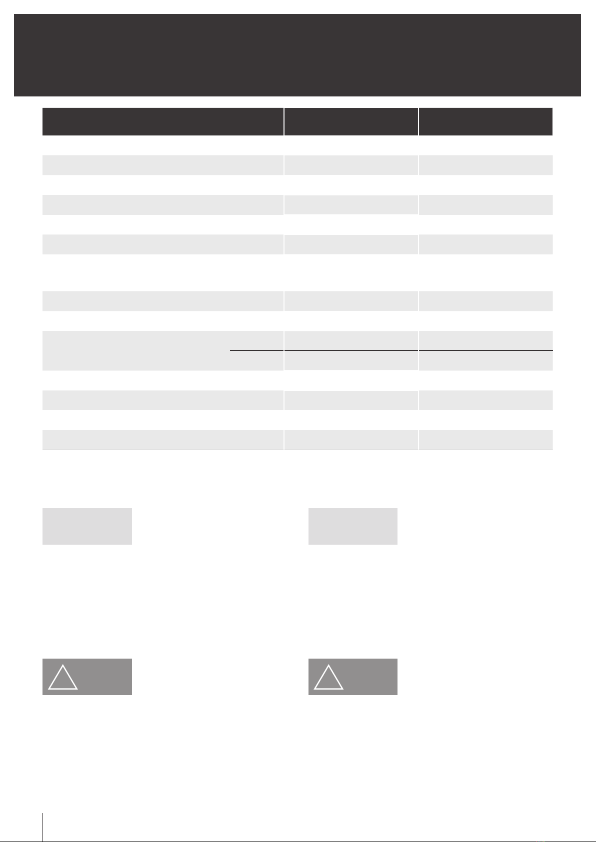
항 목 / Item RHB-250 RHB-400
테이블 직경 / Table Diameter [mm] 240 400
테이블 높이 / Table Height [mm] 200 260
중심 높이 / Center Height [mm] - -
테이블 내경 / Table ID [mm] Ø105 -
관통경 / Thru Hole Diameter [mm] Ø78 -
테이블 기준블럭 폭 / Table Reference Block Width 18H7 18H7
클램프토크 / Clamp Torque [N·m(kgf·m]
[공압 / PNE. 0.5 MPa (5.1kgf/㎠)]
[유압 / HYD. 3.5 MPa (35.6kgf/㎠)]
- 3500
클램프 방법 / Clamping Method Air / HYD. HYD.
허용적재 워크직경 / Allowable Work Diameter [mm] 250 400
허용적재 중량 / Allowable Load Weight [kg]
Horizontal 250 650
Vertical - -
관성 모멘트 / Momentum [kg·m2] 1.95 11.8
기어비 / Gear ratio 1/60 1/45
테이블최고회전속도 / Max. Rotation Speed [min-1] 66 44.4
중량 / Weight [kg] 100 380
IMPORTANT
유의사항
삼천리기계 컨트롤러 적용 모델은 앱솔루트 엔코더 부착 모터사양을 위해
출하시에 설정한 기계원점위치를 백업해 놓았습니다.
따라서 엔코더 케이블을 분리하지 마십시오.
기계원점위치의 변경을 실시할 경우는 컨트롤러의 취급설명서(기계원점 위
치 설치의항)를 참조해 주십시오.
[ 표 / Table 1 ]
IMPORTANT
The above table is based on the standard specifications. For further
details, see the appearance drawing. The maximum table rotation speed
is the value at Motor 3000min.
In order to meet the specifications of the motors attached with absolute
encoders, the starting point (origin) of the machine set up at the factory
is saved for backup. Therefore, the encoder cable must not be isolated.
To change the starting point, please refer to the section describing the
setting of the machine’s starting point in the Operation Manual of the
controller.
!CAUTION
주 의
적재중량이 허용값 내에 있어도 반드시 사양 (표 1) 을 지켜주십시오.
공작물의 중량, 형상, 절삭조건 등에 따라 심압대(Tail Stock)가 필요할 수
있습니다.
사용을 위한 모든 조건은 상기의 사양표 및 주의 항목을 참조해 주십시오.
허용값을 넘지 않도록 가공조건을 설정해 주십시오 .
!CAUTION
Even though the loaded weight is within the allowable range, please
observe the specification.
Use the tail stock as necessary according to the weight, shape, and/
orcutting condition of the work piece.
The Specification table above and the related precautions shall apply
to all the pertinent conditions of operation. Set the process parameters
within the allowable range.

11
Instruction Manual
3. 정밀도 3. Accuracy
1 2
3
6 7
4 5
측정장치에 의해 실시한다.
This work shall be conducted with a measuring instrument.
NO. 검사항목 / Inspection item RHB-250
허용치 / Allowable value
RHB-400
허용치 / Allowable value
1 회전시 테이블 흔들림 / Run-out of Table face in rotation 0.020 0.020
2 테이블 기준경 흔들림 / Center hole run-out at Table 0.020 0.020
3 테이블 윗면의 평행도 / Parallelism between Table face and Base 0.020 0.020
4 테이블 윗면의 진직도 ( 中高不可 ) / Flatness of Table face 0.020 0.020
5 백래시 / Back-lash - -
6 위치 정밀도 / Indexing accuracy 20 sec 20 sec
7 반복 정밀도 / Repeatability 4 sec 4 sec
[ 표 / Table 2 ]
(단위 / Unit : mm)
[ 그림 / Fig.1 ]

12 NC Rotary Table
4. 운전준비 4. Preparations for operation
포장상자를 열고 공작기계에 장착하여 운전에 들어가기 전 다음의 모든 점에
주의하여 준비 및 시운전을 해주십시오.
1) 운반은 부속의 아이볼트에 강도가 충분한 로프를 걸고 충격을 주지 않도
록 신중하게 행하여 주십시오.
2) 공작기계의 테이블면 로터리 테이블의 설치기 준면에 날카로운
부위나 흠집이 없는 것을 확인하여 주십시오. 날카로운 부위가 많거나 흠
집 등이 있는 경우에는 수정하여 부착해주십시오.
3) 작업에 가장 적합한 위치에 설치해주십시오. 세로 설치용 설치기준면의 가
이드블록을 공작기계의 테이블 홈에끼 워넣습니다. T홈부와 가이드블록
과의 틈이 큰 경우에는 T홈부의 한쪽으로 가까이 붙여 설치해주십시오.
4) 클램프 기구를 사용하여 로터리 테이블을 공작기계에 단단하
게 고정해주십시오.
Unpack the delivered product, and conduct the following preparations
and tests before installing it on the machine tool for production.
1) Carefully move the NC rotary table with wireropes in the eyebolts while
paying special attention to preventing any impact to the table.
2) Make sure that the mounting surface of the machine tool is free from
protrusions and scratches.
3) Install the NC rotary table on a location most adequate for operation.
Insert a guide block on the installation reference plane for vertical
installation into the groove of the table of the machine tool. If the gap
between the T slot and the guide block is large, install the product
close to either side of the T slot.
4) Use a clamping device to securely fasten the NC rotary table to the
machine tool.
4.1.1. 운반과 공작기계에의 장착 4.1.1. Transporting and mounting the
NC Rotary Table on the machine tool
!WARNING
경 고
!WARNING
경 고
!WARNING
경 고
로터리 테이블을 공작기계에 설치할 경우에는 설치 스페이스를 잘 확인하여
설치해 주십시오. 특히 공작기계의 테이블 또는 스핀들헤드 등이 이동하여
공작기계의 스플래시가드 또는 ATC장치, 스핀들헤드 등에
로터리 테이블 본체 및 케이블, 에어호스 등이 간섭되지 않도록 주의해 주십
시오.
케이블이 손상되거나 무리하게 걸거나 또는 무거운 물건을 올려놓거나 복
잡하게 틈에 끼우거나 하지 말아주십시요. 케이블이 손상되면 감전될 염려
가 있습니다.
설치자리를 유효하게 확인하고, 클램프기구의 볼트를 규정 토크로 조여
주십시오.
!WARNING
!WARNING
!WARNING
Carefully check the installation space when installing the NC rotary table
on the machine tool. In particular, exercise great care to prevent interfer-
ence of the NC rotary table body, cables and air hoses with the splash
guard, the ATC device and the spindle head of the machine tool.
Never damage, apply excessive loads, or forcibly fit cables in tight
spaces. Damage to the cable may cause electric shock.
Verify location of installation, and tighten the bolts of the clamping device
to defined torque.
4-1 설 치 4-1 Installation

13
Instruction Manual
4-2 윤 활 4-2 Lubrication
!WARNING
경 고
!WARNING
The NC rotary table is supplied with lubricant filled in the body of the NC
rotary table. Make sure that the lubricant is filled to the center line on the
gauge prior to operation.
윤활유는 틸팅 NC 로터리 테이블 본체에 이미 채워져 있습니다. 기계를
조작하기 전에 윤활유가 계기의 중심선까지 찼는지 확인하십시오.
모든 윤활유는 6개월마다 새 것으로 교체하십시오. 오일을 교체하기 전에 완
전히 배수하고 부스러기나 이물질이 탱크에 들어가지 않도록 주의하여 주십
시오. 부스러기나 이물질이 들어가면 베어링 등과 같은 중요 부품이 움직이
지 않거나 가공 정밀도가 떨어집니다. 다음 표의 권장 오일을 사용하십시오.
※ 필요유량 → 1.8L(Horizontal)
※ KOREA Houghton 비공업용 2종 ISO VG100은 이미 채워져 있습니다.
Change the lubricant every six months. When changing the lubricant,
fully drain the old oil and do not allow any debris of foreign material to
enter the tank. If contaminated with foreign material, the bearings may
become stuck and accuracy may diminish. Use the following lubricant:
※ Recommended Volume → 1.8L(Horizontal)
※ The NC rotary table is supplied with the non-industrial use Grade 2
ISO VG100 from Korea Houghton.
*권장 윤활유 (점성 등급 ISO VG100)
Recommended lubricant (Viscosity Class ISO VG100)
제조업체 / Manufacturer 오일 이름 / Product Name
KOREA Houghton 비공업용 2종 ISO VG 100 / Non-industrial use, Grade 2 ISO VG100
[ 표 / Table 3 ]

14 NC Rotary Table
4-3 클램프 시스템 4-3 Clamp System
1) HYD. input port 에 유압호스를 연결해 주십시오. 유압의 공급구(PT 3/8)
는 바디 상면에 있으므로 설치시는 외형도를 참조해 주십시오.
2) 유압의 공급압은 최대 3.5MPa(35.6kgf/cm2)이하로 사용해 주십시오.
3) 제품 본체에 위치한 CLAMP PORT에 유압 또는, 공압 호스를 연결해 주
십시오. 공급구는 본체 측면에 있으므로 설치시에 외형도를 참고해 주십시
오.
4) 유압의 공급 압력은 최대 3.5 MPa ( 35.6kgf/cm©÷ ) 이하로 사용해 주십
시오. 공압의 공급 압력은 최대 0.7 MPa ( 7.1 kgf/cm©÷ ) 이하로 사용해
주십시오.
1) Connect the HYD. hose to the HYD. input port. The HYD. input port(PT
3/8) is located on the body. See the outside drawing for installation.
2) The supply pressure of the HYD. should be less than Max. 3.5Mpa
(35.6kgf/cm2).
3) Please connect Pneumatic / Hydraulic hose with CLAMP PORT which
is located on the body. Input port is on the side of the body. Please see
the outside drawing for installation.
4) Supply pressure of hydraulic must be less than or equal to the max-
imum 3.5 MPa ( 35.6kgf/cm2) Supply pressure of pneumatic must be
less than or equal to the maximum 0.7 MPa ( 7.1 kgf/cm2)
4.3.1. 공압/유압 클램프 시스템 4.3.1. Pneumatic / Hydraulic Clamp System
[ 그림 / Fig.2 ]
[ RHB-400 ]
[ RHB-250 ]
HYD. CLAMP PORT
PT 3/8
HYD. UNCLAMP PORT
PT 3/8
AIR / HYD CLAMP PORT
HOSE Ø8mm
AIR / HYD CLAMP PORT
PT 1/4

15
Instruction Manual
4-5 공작물의 설치
4-4 에어퍼지 시스템에 관하여 4-4 About the Air purge System
4-5 Mounting a workpiece
!CAUTION
주 의
사용 상황에 따라 모터 커버 내부에 이슬이 맺힐 수 있습니다. 이슬은 전기 부
품이나 각 부품의 작동에 장애가 되기 때문에 배출구의 일부에서 공기가 배출
됩니다. 공기 분사는 클램프를 위해 공기를 사용하는 NC 로터리 테이블의 내
부에 분사된 공기에 의해 수행됩니다.
반드시 필터를 통과한 청정 공기(루브리케이터, 레귤레이터, 미스트 세퍼레이
터, 드레인)를 사용하십시오. 공기에 수분(습기), 기름기 등이 포함되어 있으면
모터 커버에 들어가서 장비 손상을 야기합니다. 모터 커버 내부의 공기는 공
기 배출구에서 배출됩니다.
공기의 일부가 막힌 경우 모터 커버 내부 부품 또는 모터 등이 손상되어 이슬
이 배출될 수 없기 때문에 공기 압력이 모터 커버에 보존됩니다. 그러므로 배
출구 부분이 닫혀서는 안됩니다.
공기가 배출할 때 배출하는 소리가 발생합니다.
※ 유압 클램프 시스템에는 별도의 에어퍼지용 에어 공급이 필요합니다.
설치시 외형도를 참조해 주십시오.
!CAUTION
Dew may be formed on the inner surface of the motor cover according
to the operating environment. Since the dew may damage electric parts
or cause malfunction of their functions, air is exhausted from a portion of
the vent. Air injection is carried out with the air injected into the NC Rotary
Table for clamping operation.
The air must be cleansed with a filter system (air filter, regulator, mist
separator, drain). Moisture (humidity) or oil mist in the air can damage the
equipment inside the motor case. The air in the motor case is discharged
out through the purge air exit.
If the air exit is clogged, the parts, components, or motor itself inside the
motor cover can be damaged and dew cannot be removed, thus, air
pressure is applied to the motor cover. As such, the air exit must be kept
open.
When the air is discharged out, the operator can hear the sound.
※ The hydraulic clamping system requires an additional purge air supply.
Refer to the outside drawing of the machine for installation.
!CAUTION
주 의
!CAUTION
주 의
평면도·수직도가 나오지 않은 공작물을 그대로 세게 조인다면 공작물이나
NC 로터리 테이블이 비뚤어져 정도 저하나 고르지 못한 회전 등이 야기 되
어질 수 있습니다. 그러한 경우에는 공작물과 NC 로터리 테이블의 사이에
조정링을 놓는 등의 고안을 해주십시오.
Fixing uneven workpiece with excessive force can make the workpiece
or the NC Rotary Table deformed, which will result in poor accuracy or
unstable rotation. For such workpieces, insert an adjusting ring between
the workpiece and the NC Rotary Table, or take other appropriate
measures.
공작물을 조립할 경우 공작물의 형상이나 가공조건에 따라 한정된 것도 있
지만 가능한 한 NC 로터리 테이블 위에 등분으로 단단히 고정하도록 부탁
드립니다.
When mounting a workpiece on the NC Rotary Table, fix it firmly at the
position where the mass of the workpiece can be distributed as uni-
formly as possible, considering the shape or process requirement.
!CAUTION
!CAUTION
!WARNING
경 고
공작물을 단단히 설치하지 않을 경우 정도가 나빠질 뿐만 아니라 기계·공
구의 손상, 최악의 경우에는 인사 사고로도 이어질 수 있으므로 특히 주의해
주십시오.
If the workpiece is not mounted firmly, the precision of the process will
be deteriorated, or even worse, damage of the machine and/or tool or
injury/death of the operator may occur.
!WARNING

16 NC Rotary Table
5. 점검작업
6. NC 로터리테이블
클램프의 설명
5. Inspection
6. Description of the
NC Rotary table
5-1 일일점검
5-2 정기점검
5-1 Daily Inspection
5-2 Periodic Inspection
6-1 테이블 클램프의 주의사항 6-1 Cautions for the Table Clamp
1) NC 로터리 테이블
(지그를 설치할 경우는 지그도 포함)의 고정상태를 확인
2) 전기의 접속 케이블 및 호스에 손상이 없는지의 확인과 공압 체크
3) 산출동작, 위치의 확인
4) 이상 진동, 이상 음은 없는지 확인 (본체, 모터)
5) 이상 발열은 없는지 확인 (본체, 모터)
(6개월 마다 다음의 항목의 점검을 행하여 주십시오.)
1) 윤활유의 오염 상태
2) 커넥터류의 설치 확인, 케이블 관계의 파손이 없는지 확인
3) 모터 케이스내의 배선관계의 부식, 단선의 점검
1) Check the fixing of the NC Rotary Table
(including the jig, if installed).
2) Check the cable and hose for damage. Check the air pressure.
3) Check calculation and positioning
4) Check for any vibration or abnormal noise (main body, motor)
5) Check for any abnormal heat (main body, motor)
(Check the following items every six months:)
1) Contamination of the lubricant
2) Condition of the connectors, damaged cable.
3) Corrosion, open circuit in the motor casing.
!CAUTION
주 의
!CAUTION
주 의
!CAUTION
주 의
테이블의 회전은 반드시 언클램프의 상태로 사용하시고 위치를 정한 후 가공
은 클램프 상태로 사용해 주십시오. 잘못된 사용은 웜기어의 손상으로 이어
지므로 주의해 주십시오. (클램프·언클램프를 확인하려면 압력 스위치의 신
호를 이용해 주십시오.)
사양에 기재의 클램프 토크 이상을 필요로 하는 가공은 피해주십시오. 클램
프 부분의 마모와 웜 기어의 손상으로 이어질 수 있습니다.
언클램프시에 잔류압이 남아 있으면 완전히 클램프 상태가 해제되지 않고 반
클램프의 상태로 운전하는 경우가 있습니다. 이러한 경우에는 웜기어 부분,
클램프 부분의 소착, 손상 등의 직접 원인이되 므로 압력배출에 충분히 주의
해주십시오.
The Rotary Table must be rotated while unclamped, and processing
after positioning must be performed while clamped. Incorrect use will
result in damage to the worm gear. You can check the clamped / un-
clamped status with the signal of the pressure switch.
Do not exceed the clamping torque defined in the specification. Other-
wise, the clamp may become worn and/or damage to the worm gear
may occur.
If there is residual pressure during unclamping the table, clamping is not
fully released, and the table may be semi-clamped. These conditions
directly burn and damage the worm gear and internal parts related to
clamping. Confirm that pressure is fully released during unclamp.
!CAUTION
!CAUTION
!CAUTION

17
Instruction Manual
6-3 클램프·언클램프용 압력 센서
6-2 Pressure Sensor for Clamp, Unclamp
[ 그림 / Fig.3 ]
6-2 클램프·언클램프 확인장치 6-2 Clamp, Unclamp Check Device
확실한 작업진행을 위해서 반드시 클램프·언클램프 확인신호를 이용해
주십시오. 압력 스위치의 설정압은 각 클램프 방식에 따라서 다음의 (표 4)
와 같습니다
To prevent mistakes, be sure to check the clamp/unclamp signal. The
pressure setting of the pressure switch is as follows, according to the
methods of clampin. (See Table 4)
클램프 확인 / Confirm Clamp 언클램프 확인 / Confirm Unclamp
공압 클램프
Air Clamp
0.25 MPa (3.0 kgf/cm2)
(PS1000-R06 : SMC )
0.2 MPa (2.0 kgf/cm2)
(0166-413-03-051 : SUCO)
유압 클램프
HYD. clamp
2.0 MPa (20.0 kgf/cm2)
(0166-40630-023 SUCO)
0.2 MPa (2.0 kgf/cm2)
(0166-413-03-051 SUCO)
[ 표 / Table 4 ]
[ RHB-400 ]
[ RHB-250 ]
CLAMP PRESSURE SENSOR
( 0166-40630-023 : SUCO )
UNCLAMP PRESSURE SENSOR
( 0166-413-03-051 : SUCO )
SERVO MOTOR
CLAMP / UNCLAMP SENSOR
SOLENOID VALVE
SERVO MOTOR
+-

18 NC Rotary Table
7. 구성품 설명 및
유지보수·조정
7.
Description, maintenance and
adjustment of components
7-1 웜기어의 백래시 조정 7-1
Adjustment of wormgear Backlash
웜샤프트 및 웜휠에는 특수한 재료를 사용하여 극히 정밀한 가공으로 우수한
정도를 갖게 합니다.
웜샤프트, 웜휠의 백래쉬 제거 방법으로서 듀얼리드 웜(DUAL LEAD
WORM)을 사용하고 있습니다. 이것은 웜샤프트의 좌우 치면의 리드를 다르
게 변경하여 웜샤프트를 축방향으로 이동시켜 웜휠의 백래쉬를 조정하게 됩
니다.
이 듀얼리드 웜 방식은 가장 이상적인 치면의 백래쉬를 미세하게 조정할 수
있고 이론적으로도 실제적으로도 가장 정확한 백래쉬 조정이 가능합니다.
웜기어의 백래쉬는 출하 시에 적정치로 조정되어 있지만 장시간의 사용중에
는 조정이 필요한 경우도 있습니다. 백래쉬 적정치는 아래 [표5]에 기재했습
니다. 이 값은 기계 냉각 시, 즉 장시간 휴지 후에 상정한 값입니다. 따라서 장
시간 연속 운전한 경우에는 열팽창에 의한 값보다 백래쉬는 작아집니다.
The worm shaft and the worm wheel are manufactured withsuperior
materials under a precision process. A dual-lead worm is applied as a
countermeasure against the backlash of the worm shaft and the worm
wheel. This method is implemented with a differentiated lead between
the left-and right-hand teeth surfaces of the worm shaft, which shifts the
worm shaft towards the spindle.
This dual-lead worm method is acknowledged as the best method
both theoretically and practically. It enables very fine adjustment of the
backlash of the teeth.
The backlash of the worm gear was adjusted appropriately at the
factory; however, readjustment may be necessary after a long period of
operation. The table below presents the optimal value of the backlash.
The value is measured when the machine has cooled down, some time
after shut down. Consequently, the real backlash value after a period
of operation is less than the optimal value due to thermal expansion.
Worm gear will not move if backlash is excessively low.
Measure backlash before adjusting.
!CAUTION
!CAUTION
주 의
백래시가 너무 작으면 웜 기어가 움직이지 않습니다.
※ 적합한 백래쉬 / Appropriate Backlash
백래시를 조정하기 전에 다음 방법으로 현재 백래시를 측정 후에 백래시를
조정합니다.
1) 테이블 상면의 T-SOLT 측면에 다이얼게이지를 셋트합니다.
2) 테이블 상면의 탭홀(TAP HOLE)을 이용하여 평강(평평한 강철) 또는 환봉
을 넣고 테이블을 천천히 회전시켜 웜휠의 치가 웜샤프트에 꼭 끼는 위치
에서 손을 떼고 다이얼게이지의 값을 알아냅니다. 다음에 반대방향에 동일
조건으로 웜샤프트에 치가 꼭 낄 때까지 회전시킵니다. 이때의 측정값의 차
가 백래시량입니다.
3) 상기 측정은 테이블을 회전시켜 45°마다 8개소에서 실시하고 앞서 기록
한 적정값과 비교해 주십시오.
적정값보다 빗나가는 경우에는 이하에 나타낸 요령으로 조정해 주십시오.
백래시의 최소값이 앞에 기재한 적정값으로 되도록 조정해주십시오.
(그림 5)
1) Set a dial gauge on the side of the T-SOLT on top of the table.
2) Insert a steel plate or rod into the tap hole on top of the table, then turn
the table slowly. When the teeth of the worm wheel contact the worm
shaft firmly, stop turning and read the measurement on the dial gauge.
Turn the table in the opposite direction until the work wheel teeth con-
tact the worm shaft firmly, and read the dial gauge. The difference
between the two values is the backlash.
3) Perform the above measurement 8 times at every 45°position of the
table. Compare the measurements with the optimal value presented
earlier. Adjust the deviation from the optimal value by the following pro-
cedures. Adjust the backlash so that the minimum value is the same as
the optimal value. (Fig 5)
7.1.1. 웜기어의 백래시 측정 7.1.1. Method of Measuring Worm Gear Backlash
테이블 형식 / Appropriate backlash RHB-250 RHB-400
테이블 끝단에서의 원호 길이 [㎛]
/ Length of the arc from the tip of the tabl 13-41 14~41
중심에서 반경
/ Radius from the center
피치원 반경[mm]
/ Pitch circle radius 91 144
테이블 끝단[mm]
/ Tip of the table 125 200
[ 표 / Table 5 ]

19
Instruction Manual
1) 조정하기 전에 테이블의 공작물, 지그 등을 제거하고 테이블의 수평을 맞
추십시오. (그림 5, 5-1 참조)
2) 배출구에서 윤활유를 제거합니다.
3) 백래시를 조절하기 전, 본체의 ⓐPT PLUG를 제거 합니다.
4) 길이가 긴 렌치를 이용하여 ⓑ커플링 조임 볼트를 풀어줍니다.
( 주의 : 커플링을 잡고 있는 볼트를 대략 3~4바퀴만 풀어줍니다. )
5) ①HOUSING COVER를 제거합니다.
6) ②HOUSING PLUG를 제거합니다.
7) ③HOUSING 정면에 체결된 ④SETSCREW 3개소를 느슨하게 풀고
③HOUSING 정면에 체결되지 않은 곳에 BOLT를 2개소 부분에 체결합니
다. (HOUSING 회전에 필요)
8) ③HOUSING에 체결한 BOLT를 손으로 잡고 회전하여 백래시량을 조정
한 후 ⑤WORM SHAFT 육각 홈 부분에 T-WRENCH를 삽입하여 백래시
량의 정도를 확인합니다. (참고: 백래시량 측정방법은 본 설명서 18 Page
WORMGEAR BACKLASH 조정법에 기재되어 있으니 확인하시기 바랍니
다. 백래시는 시계방향으로 회전할수록 작아집니다.)
9) 백래시 조정이 완료되면 ③HOUSING 전면에 체결된 ④SETSCREW 3개
소를 완전히 잠그고 BOLT 2개소 제거합니다.
10) 백래시 조정을 종료합니다.
1) Before adjusting backlash, remove the workpiece and jig from the
table, and set the table in horizontal position. (Fig 5, 5-1)
2) Remove lubricant from the exit.
3) Before adjusting backlash, Please remove ⓐPT PLUG on the body.
4) Please us long wrench in order to loosen ⓑCoupling fix bolt.
( CAUTION : Please loosen ⓑCoupling fix bolt 3 to 4 full turns.
5) ①Remove the housing cover.
6) ①Remove the housing plug.
7) Loosen three ④screws on the front of the ③housing. Install bolts
into the two taps on the front of the ③housing where there is no bolt
(Required for turning the housing).
8) Adjust the backlash by turning the housing ③with the bolts using
hands. Insert a T-wrench into the hexagonal recess of the ⑤worm
shaft. (Note: refer to Worm Gear Backlash Adjustment, page 18 of
this manual. The backlash is reduced when the housing is turned
clockwise.)
9) When the backlash has been adjusted, tighten the three ④screws on
the front of the ③housing, and remove the two bolts.
10) Backlash adjustment is completed.
7.1.2 웜 기어 백래시 조정 7.1.2. Adjusting backlash of worm gear
백래시 조정을 할 경우에는 반드시 제어장치의 전원을 OFF, 또한 NC 로터리
테이블을 언클램프 상태로 한 후에 조정해 주십시오. 회전중에 잘못하여 손
이나 의복이 기어에 닿으면 말려들어가 큰 사고로 연결될 염려가 있으니 주
의하십시오.
When adjusting backlash, the power of the controller must be turned
off and the NC Rotary Table must be unclamped. Your body or clothes
can be caught in the machine during rotation, which leads to a serious
accident.
!DANGER
위 험 !DANGER
[ 그림 / Fig.4 ]
[ 그림 / Fig.5 ]
WRENCH BOLT 체결 부위
/ WRENCH BOLT JOINT
③ HOUSING ⑤ WORM SHAFT
① HOUSING COVER
② HOUSING
PLUG
④ SET SCREW
⑥ O-RING

20 NC Rotary Table
조정한 후 전술한 절차의 역순으로 웜 기어를 재조립하고 볼트를 단단히
조이십시오. 재조립한 후 테이블의 바깥쪽 주변장치와 동일한 위치에서
백래시를 다시 측정하여 백래시가 적절한지 확인하십시오.
커플링 조임 볼트를 완전히 풀면 볼트가 이탈하니 주의 하십시오.
커플링 조임 볼트를 풀지 않고 백래시를 조절하면, 커플링이 파손 될 수 있
습니다.
When the adjustment has been completed, reassemble the worm
gear in the reverse order of disassembly and tighten the bolts. After
reassembling, measure the backlash again at the same position to the
peripheral devices of the table to confirm
that the adjustment is satisfactory.
Please be careful in not loosening the coupling bolts completely which
may result in the bolts falling out.
Please make sure unless the Coupling Fix Bolt is loosened, Coupling
could get damaged.
IMPORTANT
유의사항
HOUSING을 시계방향(CW)으로 1회전하면 백래시는 작아집니다.
IMPORTANT
The backlash is reduced when the housing is rotated by on turn
clockwise.
!CAUTION
주 의
백래시를 성급하게 조정하지 마십시오. 천천히 조심스럽게 조정하십시오.
!CAUTION
Do not adjust the backlash abruptly. Adjust it slowly and carefully.
[ 그림 / Fig.5-1 ]
Back Lash 조절 시
Coupling Lock Bolt를
해제 하십시요.
Back Lash 조절 시
Coupling Lock Bolt를
해제 하십시요.
ⓐ PT PLUG ⓐ PT PLUG
ⓑ 커플링 조임 볼트
This manual suits for next models
1
Table of contents
Other SAMCHULLY Power Tools manuals
Popular Power Tools manuals by other brands

Facom
Facom Y.135F instruction manual

Makita
Makita DUP362Z instruction manual

ACDelco
ACDelco ARI12104 Product information manual

Rose electronics
Rose electronics TORQUE WRENCH PRO 1-25 NM owner's manual

General International
General International 75-060 Setup & operation manual

General International
General International DP2006 Setup and operation manual