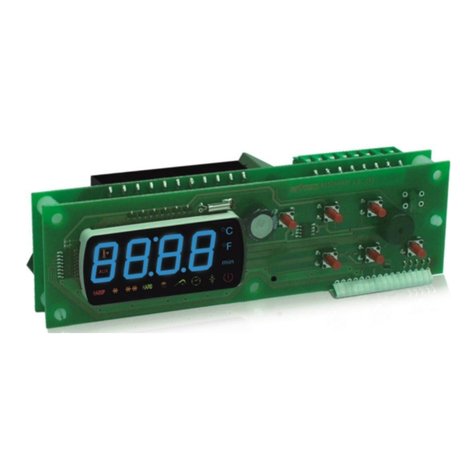
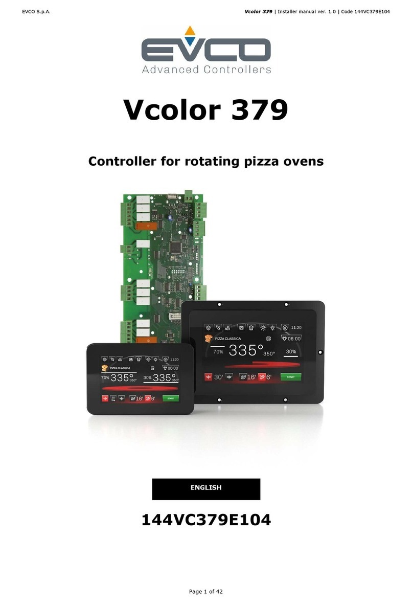
Evco EV3 HP User guide

EVCO S.p.A. EV3 HP & EVD HP | Installer manual ver. 1.1 | Code 1443DHPE114
page 1 of 50
EV3 HP & EVD HP
Controllers for reversible single-circuit
residential heat pumps
Installer Manual | ENGLISH
Code 1443DHPI114

EVCO S.p.A. EV3 HP & EVD HP | Installer manual ver. 1.1 | Code 1443DHPE114
page 2 of 50
Important
Read this manual carefully before installation and before using the devices and take all the prescribed precautions. Keep this manual
with the devices for future consultation.
Only use the devices in the ways described in this manual. Do not use these devices as safety devices.
Disposal
The devices must be disposed of according to local regulations governing the collection of electrical and electronic waste.

EVCO S.p.A. EV3 HP & EVD HP | Installer manual ver. 1.1 | Code 1443DHPE114
page 3 of 50
Index
1INTRODUCTION ......................................................................................................................................................... 5
1.1 Introduction .............................................................................................................................................................. 5
1.2 Models available, purchasing codes and technical features .............................................................................................. 6
2DESCRIPTION............................................................................................................................................................ 8
2.1 Description of EV3 HP ................................................................................................................................................. 8
2.2 Description of EVD HP................................................................................................................................................. 9
2.3 Description of EV3K01 .............................................................................................................................................. 10
3MEASUREMENTS AND INSTALLATION ......................................................................................................................... 11
3.1 Measurements and installation of EV3 HP .................................................................................................................... 11
3.2 Measurements and installation of EVD HP ................................................................................................................... 11
3.3 Measurements and installation of EV3K01 ................................................................................................................... 13
3.4 Installation precautions............................................................................................................................................. 13
4ELECTRICAL CONNECTION ........................................................................................................................................ 14
4.1 I/O configuration ..................................................................................................................................................... 14
4.2 Description of connectors .......................................................................................................................................... 15
4.2.1 Description of connectors for EV3 HP .......................................................................................................................... 15
4.2.2 Description of connectors for EVD HP.......................................................................................................................... 17
4.2.3 Description of EV3K01 connectors .............................................................................................................................. 19
4.3 Fitting the termination resistor to the RS-485 MODBUS slave port.................................................................................. 20
4.4 Example of electrical connection ................................................................................................................................ 21
4.4.1 Example of EV3 HP electrical connection ..................................................................................................................... 21
4.4.2 Example of EVD HP electrical connection ..................................................................................................................... 22
4.5 Precautions for electrical connection ........................................................................................................................... 23
5DESCRIPTION OF USER INTERFACE ........................................................................................................................... 24
5.1 Key functions .......................................................................................................................................................... 24
5.2 Display ................................................................................................................................................................... 24
5.3 Signals ................................................................................................................................................................... 25
5.4 Menu ...................................................................................................................................................................... 27
5.4.1 Access levels ........................................................................................................................................................... 27
5.4.2 Menu list................................................................................................................................................................. 27
6LIST OF PARAMETERS .............................................................................................................................................. 28
6.1 Initial information .................................................................................................................................................... 28
7REGULATORS .......................................................................................................................................................... 33
7.1 Initial information .................................................................................................................................................... 33
7.2 Function mode......................................................................................................................................................... 33
7.3 Compressor............................................................................................................................................................. 33
7.3.1 Adjustment in cold mode .......................................................................................................................................... 33
7.3.2 Adjustment in hot mode ........................................................................................................................................... 34
7.3.3 Oil refresh............................................................................................................................................................... 34
7.4 Hydraulic pump ....................................................................................................................................................... 35
7.4.1 Initial information .................................................................................................................................................... 35
7.4.2 Function modes ....................................................................................................................................................... 35
7.4.3 Antifreeze function ................................................................................................................................................... 35
7.5 Electric heating elements .......................................................................................................................................... 36
7.5.1 Initial information .................................................................................................................................................... 36
7.5.2 Heating elements in integration mode ........................................................................................................................ 36
7.5.3 Heating elements in antifreeze mode.......................................................................................................................... 36
7.6 Condensation control ................................................................................................................................................ 37
7.6.1 Initial information .................................................................................................................................................... 37
7.6.2 Adjustment in cold mode .......................................................................................................................................... 37
7.6.3 Adjustment in hot mode ........................................................................................................................................... 38
7.7 Defrost ................................................................................................................................................................... 39
7.7.1 Initial information .................................................................................................................................................... 39
7.7.2 Start defrost control ................................................................................................................................................. 39

EVCO S.p.A. EV3 HP & EVD HP | Installer manual ver. 1.1 | Code 1443DHPE114
page 4 of 50
7.7.3 End defrost control................................................................................................................................................... 39
8ALARMS .................................................................................................................................................................. 40
8.1 Initial information .................................................................................................................................................... 40
8.2 List of alarms .......................................................................................................................................................... 40
9ACCESSORIES ......................................................................................................................................................... 42
9.1 EVIF20SUXI non-optoisolated RS-485/USB serial interface ............................................................................................ 42
9.1.1 Initial information .................................................................................................................................................... 42
9.2 0025100010 drip protector........................................................................................................................................ 42
9.2.1 Initial information .................................................................................................................................................... 42
9.3 CJAV connection kit .................................................................................................................................................. 42
9.3.1 Initial information .................................................................................................................................................... 42
10 TECHNICAL SPECIFICATIONS .................................................................................................................................... 43
10.1 Technical specifications..........................................................................................Errore. Il segnalibro non è definito.

EVCO S.p.A. EV3 HP & EVD HP | Installer manual ver. 1.1 | Code 1443DHPE114
page 5 of 50
1INTRODUCTION
1.1 Introduction
EV3 HP and EVD HP are controllers for reversible air-water and
water-water single-circuit residential heat pumps.
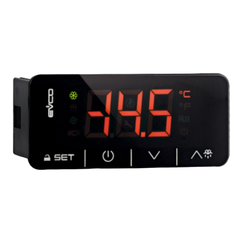
EV3 HP is available in the standard 74x32mm format with
built-in user interface consisting of a double custom display,
with decimal point and function icons, and four touch keys. It
guarantees IP65 protection for easy cleaning.
EVD HP is available in standard 4-module DIN format, in a
blind version that can be connected to a remote user interface
(EV3K01) if required.
These controllers are capable of running compressors and fans
of both the on-off and modulating types.
EV3 HP is available with a 12VAC power supply, while EVD HP
can be supplied with a 115... 230VAC power supply.
EV3 HP is designed to be installed on a panel with snap-in
brackets, while EVD HP is fitted to a DIN rail in a control panel.

EVCO S.p.A. EV3 HP & EVD HP | Installer manual ver. 1.1 | Code 1443DHPE114
page 6 of 50
1.2 Models available, purchasing codes and technical features
The table below shows the models available, the purchasing codes and the technical features of the devices.
COMPACT VERSION SPLIT VERSION
Models available > EV3 HP EVD HP EV3K01
Purchasing codes > EV3914LM2 EV3916LM2GF EVD914BM9 EV3K01XOCT
Version
Blind •
Built-in LED (4+4 digit custom display) • • •
Connections
Micro-Fit connectors • • •
Edge connectors • •
Plug-in screw terminal blocks • • • •
Power supply
12VAC not insulated • •
12VAC/DC not insulated •
115 - 230VAC insulated •
Analogue inputs
NTC 3 3 3
NTC/4-20 mA 1 1 1
Digital inputs
Dry contact 6 6 6
Analogue outputs
0-10V/phase cutting/PWM 1 1 1

EVCO S.p.A. EV3 HP & EVD HP | Installer manual ver. 1.1 | Code 1443DHPE114
page 7 of 50
COMPACT VERSION SPLIT VERSION
Models available > EV3 HP EVD HP EV3K01
Purchasing codes > EV3914LM2 EV3916LM2GF EVD914BM9 EV3K01XOCT
Digital outputs (electro-mechanical relays; A res. @ 250 VAC)
2A SPST 4 4
3A SPST 2
8A SPDT 1
12A SPST 1
Digital outputs (triac; A res. @ 250 VAC)
200mA 1
2A 1
Digital outputs (open collector)
12VDC, max. 40mA 1
Communications ports
Powered INTRABUS • • • •
Other features
Alarm buzzer • • •
Notes Optional extras
None - Clock (not available for model EV3K01)
- RS-485 MODBUS slave port (not available for model
EV3K01).
The purchasing codes for EV3 HP and EVD HP do not include the cabling connectors, see the ACCESSORIES section.
For more models contact the EVCO sales network.

EVCO S.p.A. EV3 HP & EVD HP | Installer manual ver. 1.1 | Code 1443DHPE114
page 8 of 50
2DESCRIPTION
2.1 Description of EV3 HP
The picture below shows the layout of the EV3 HP.
The table below describes each part of the EV3 HP.
PART DESCRIPTION
1 Double custom display, with decimal point and function icons
2 On/Off key, subsequently also called the On/Stand-by key
3 Decrease key, subsequently also called the Down key
4 Increase key, subsequently also called the Up key
5 Setting key, subsequently also called the Set key
6 Micro-switch for the termination resistor for the RS-485 MODBUS slave port
7 Seal
8 Edge connector joint for the digital output cabling with electro-mechanical relay (for future reference, the digital outputs
DO1... DO4)
9 Male Micro-Fit connector for cabling for the power supply, analogue inputs, digital inputs, analogue outputs and the
INTRABUS powered port.
10 If fitted, plug-in screw terminal block, male only, for cabling for the RS-485 MODBUS slave port
11 If fitted, the joint of the Edge connector for the triac digital output cabling (for future reference, the digital output TK1).
12 If fitted, the joint of the Edge connector for the triac digital output cabling (for future reference, the digital output TK2)
For more information see subsequent sections.

EVCO S.p.A. EV3 HP & EVD HP | Installer manual ver. 1.1 | Code 1443DHPE114
page 9 of 50
2.2 Description of EVD HP
The picture below shows the layout of the EVD HP.
The table below describes each part of the EVD HP.
PART DESCRIPTION
1 Male Micro-Fit connector for cabling for analogue inputs, digital inputs, analogue outputs and the open collector digital
output (for future reference, the digital output OC1)
2 Micro-switch for the termination resistor for the RS-485 MODBUS slave port
3 If fitted, plug-in screw terminal block, male only, for cabling for the RS-485 MODBUS slave port
4 Plug-in screw terminal block, male only, for cabling for the powered INTRABUS port
5 Plug-in screw terminal block, male only, for cabling for the digital outputs with electro-mechanical relay (for future
reference, the digital outputs DO1 and DO2)
6 Plug-in screw terminal block, male only, for cabling for the power supply, electrical-mechanical relay digital outputs (for
future reference, the digital outputs DO3 and DO4)
For more information see subsequent sections.

EVCO S.p.A. EV3 HP & EVD HP | Installer manual ver. 1.1 | Code 1443DHPE114
page 10 of 50
2.3 Description of EV3K01
The picture below shows the layout of the EV3K01.
The table below describes each part of the EV3K01.
PART DESCRIPTION
1 Double custom display, with decimal point and function icons
2 On/Off key, subsequently also called the On/Stand-by key
3 Decrease key, subsequently also called the Down key
4 Increase key, subsequently also called the Up key
5 Setting key, subsequently also called the Set key
6 Seal
7 Male + female plug-in screw terminal block for cabling for the power supply and the powered INTRABUS port
8 Not used
For more information see subsequent sections.

EVCO S.p.A. EV3 HP & EVD HP | Installer manual ver. 1.1 | Code 1443DHPE114
page 11 of 50
3MEASUREMENTS AND INSTALLATION
3.1 Measurements and installation of EV3 HP
The pictures below show the measurements of EV3 HP; measurements are expressed in mm (inches).
To be installed on a panel with snap-in brackets provided.
The thickness of the panel on which EV3 HP is to be installed must be between 0.8 and 2.0mm (0.031 and 0.078 in).
3.2 Measurements and installation of EVD HP
The picture below shows the measurements of EVD HP (4 DIN modules); measurements are expressed in mm (inches).

EVCO S.p.A. EV3 HP & EVD HP | Installer manual ver. 1.1 | Code 1443DHPE114
page 12 of 50
Installation is on a DIN rail 35.0 x 7.5mm (1.377 x 0.295 in) or 35.0 x 15.0mm (1.377 x 0.590 in), in a control panel.
The pictures below show how to install the EVD HP.
12
To remove the EVD HP, first remove any plug-in screw terminal blocks fitted in the lower part, then, using a screwdriver, loosen the
DIN rail clip, as shown in the pictures below.
34
To re-install the EVD HP first press the DIN rail clip fully in.

EVCO S.p.A. EV3 HP & EVD HP | Installer manual ver. 1.1 | Code 1443DHPE114
page 13 of 50
3.3 Measurements and installation of EV3K01
The pictures below show the measurements of EV3K01; measurements are expressed in mm (inches).
To be installed on a panel with snap-in brackets provided.
The thickness of the panel on which the EV3K01 is to be installed must be between 0.8 and 2.0mm (0.031 and 0.078 in).
3.4 Installation precautions
- Ensure that the working conditions for the devices (operating temperatures, humidity, etc.) are within the set limits. See
the section TECHNICAL SPECIFICATIONS.
- Do not install the devices close to heat sources (heating elements, hot air ducts, etc.), equipment with a strong magnetic
field (large diffusers, etc.), in places subject to direct sunlight, rain, damp, excessive dust, mechanical vibrations or shocks.
- In compliance with safety regulations, the devices must be installed properly to ensure adequate protection from contact
with electrical parts. All protective parts must be fixed in such a way as to need the aid of a tool to remove them.

EVCO S.p.A. EV3 HP & EVD HP | Installer manual ver. 1.1 | Code 1443DHPE114
page 14 of 50
4ELECTRICAL CONNECTION
4.1 I/O configuration
The table below shows the I/O configuration.
ANALOGUE INPUTS EV3914LM2 EV3916LM2GF EVD914BM9
IN1 Condensation temperature/pressure (NTC/4-20
mA) • • •
IN2 Input water temperature (NTC) • • •
IN3 Output water temperature (NTC) • • •
IN4 Compressor discharge temperature (NTC) • • •
IN5 Battery temperature (NTC) •••
DIGITAL INPUTS EV3914LM2 EV3916LM2GF EVD914BM9
IN10 System flow switch • • •
IN9 Fan thermal protection • • •
IN8 Compressor thermal protection • • •
IN7 Maximum pressure switch • • •
IN6 Minimum pressure switch • • •
ANALOGUE OUTPUTS EV3914LM2 EV3916LM2GF EVD914BM9
AO1 Compressor (0-10V/phase cutting/PWM) • • •
AO2 Fan (0-10V/phase cutting/PWM) • • •
DIGITAL OUTPUTS EV3914LM2 EV3916LM2GF EVD914BM9
DO1 Reversing valve • • •
DO2 Enable fan • • •
DO3 Circulation pump • • •
DO4 Enable compressor • • •
TK1 Boiler/system heating element enable •
TK2 Fan •
OC1 Boiler/system heating element enable •

EVCO S.p.A. EV3 HP & EVD HP | Installer manual ver. 1.1 | Code 1443DHPE114
page 15 of 50
4.2 Description of connectors
4.2.1 Description of connectors for EV3 HP
The picture below shows the layout of the EV3 HP connectors.
The tables below describe the EV3 HP connectors.
Connector 1
PART DESCRIPTION
1 Electro-mechanical relay digital outputs DO1... DO4 (max. 6A): common
2 Electro-mechanical relay digital output DO4 (2 A SPST): normally open
3 Electro-mechanical relay digital output DO3 (2 A SPST): normally open
4 Electro-mechanical relay digital output DO2 (2 A SPST): normally open
5 Electro-mechanical relay digital output DO1 (2 A SPST): normally open
Connector 2
PART DESCRIPTION
1 Dry contact digital input IN10
2 Analogue input IN1 (NTC/4-20 mA)
3 Dry contact digital input IN9
4 Analogue input IN2 (NTC)
5 Dry contact digital input IN8
6 Analogue input IN3 (NTC)
7 Dry contact digital input IN7

EVCO S.p.A. EV3 HP & EVD HP | Installer manual ver. 1.1 | Code 1443DHPE114
page 16 of 50
8 Analogue input IN4 (NTC)
9 Dry contact digital input IN6
10 Analogue input IN5 (NTC)
11 Analogue output AO1 (0-10V/phase cutting/PWM)
12 Analogue input GND, digital input GND, analogue output GND and GND for powered INTRABUS port
13 Analogue output AO2 (0-10V/phase cutting/PWM)
14 INTRABUS port powered up signal
15 Power supply to transducer analogue inputs 4-20 mA (12 VDC, max. 40 mA)
16 Analogue input GND, digital input GND, analogue output GND and GND for powered INTRABUS port
17 EV3 HP power supply (12VAC not insulated)
18 EV3 HP power supply (12VAC not insulated)
Connector 3 (if installed)
PART DESCRIPTION
1 RS-485 MODBUS slave port: +
2 RS-485 MODBUS slave port: -
3 RS-485 MODBUS slave port: shield
Connector 4 (if installed)
PART DESCRIPTION
1 Triac TK1 output: GND
2 Triac TK1 output (200 mA): OUT
Connector 5 (if installed)
PART DESCRIPTION
1 Triac TK2 output: GND
2 Triac TK2 output (2 A): OUT

EVCO S.p.A. EV3 HP & EVD HP | Installer manual ver. 1.1 | Code 1443DHPE114
page 17 of 50
4.2.2 Description of connectors for EVD HP
The picture below shows the layout of the EVD HP connectors.
The tables below describe the EVD HP connectors.
Connector 1
PART DESCRIPTION
1 Electro-mechanical relay digital output DO1 (3A SPST): normally open
2 Electro-mechanical relay digital output DO2 (3A SPST): normally open
3 Electro-mechanical relay digital outputs DO1 and DO2 (max. 6A): common
Connector 2
PART DESCRIPTION
1 Electro-mechanical relay digital output DO3 (12A SPST): normally open
2 Electro-mechanical relay digital output DO3 and D04 (max. 6A): common
3 Electro-mechanical relay digital output DO3 and D04 (max. 6A): common
4 Electro-mechanical relay digital output DO4 (8A SPDT): normally open
5 Electro-mechanical relay digital output DO4 (8A SPST): normally closed
6 Not used
7 EVD HP power supply (115... 230 VAC insulated)
8 EVD HP power supply (115... 230 VAC insulated)

EVCO S.p.A. EV3 HP & EVD HP | Installer manual ver. 1.1 | Code 1443DHPE114
page 18 of 50
Connector 3
PART DESCRIPTION
1 Analogue output AO2 (0-10V/phase cutting/PWM)
2 Analogue outlet AO1 (0-10V/phase cutting/PWM)
3 EV3K01 power supply GND, analogue input GND, digital input GND, analogue output GND and GND for powered
INTRABUS port
4 Analogue input IN1 (NTC/4-20 mA)
5 Dry contact digital input IN10
6 Analogue input IN2 (NTC)
7 Dry contact digital input IN9
8 Analogue input IN3 (NTC)
9 Dry contact digital input IN8
10 Analogue input IN4 (NTC)
11 Dry contact digital input IN7
12 Analogue input IN5 (NTC)
13 EV3K01 power supply GND, analogue input GND, digital input GND, analogue output GND and GND for powered
INTRABUS port
14 Dry contact digital input IN6
15 Not used
16 EV3K01 power supply and power supply for transducer analogue inputs 4-20mA (12 VDC, max. 120mA)
17 Open collector digital output OC1 (12V, max. 40mA)
18 EV3K01 power supply GND, analogue input GND, digital input GND, analogue output GND and GND for powered
INTRABUS port

EVCO S.p.A. EV3 HP & EVD HP | Installer manual ver. 1.1 | Code 1443DHPE114
page 19 of 50
Connector 4 (if installed)
PART DESCRIPTION
1 RS-485 MODBUS slave port: shield
2 RS-485 MODBUS slave port: -
3 RS-485 MODBUS slave port: +
Connector 5
PART DESCRIPTION
1 EV3K01 power supply GND and GND for powered INTRABUS port
2 INTRABUS port powered up signal
3 EV3K01 power supply
4.2.3 Description of EV3K01 connectors
The picture below shows the layout of the EV3K01 connectors.
The table below describes the EV3K01 connectors.
Connector 1
PART DESCRIPTION
1 EV3K01 (12 VAC/DC) power supply; if EV3K01 is fed by DC power, connect the positive pole
2 Not used
3 INTRABUS port powered up signal
4 EV3K01 power supply GND and GND for powered INTRABUS port

EVCO S.p.A. EV3 HP & EVD HP | Installer manual ver. 1.1 | Code 1443DHPE114
page 20 of 50
4.3 Fitting the termination resistor to the RS-485 MODBUS slave port
To reduce reflections on the signal transmitted along the cables connecting the devices to a RS-485 network it is necessary to fit a
termination resistor to the first and last element in the network.
To fit the EV3 HP termination resistor, place micro-switch 1 in position ON. Do not touch micro-switch 2.
To fit the EVD HP termination resistor, place micro-switch 1 in position ON.
This manual suits for next models
2
Table of contents
Other Evco Controllers manuals

Evco
Evco EV3 700 Series User manual

Evco
Evco EV3802 User manual

Evco
Evco EV3B71 User manual

Evco
Evco C-PRO CLIMA SYSTEMA User guide

Evco
Evco EVJ 200 Series User manual

Evco
Evco Vcolor 318 M User guide

Evco
Evco EV3143 User manual

Evco
Evco EV9376 User manual

Evco
Evco c-pro 3 Series User manual

Evco
Evco EV3 Mix User manual
Popular Controllers manuals by other brands

ENSIM SENSORS
ENSIM SENSORS SK-R operating manual

Nederman
Nederman Fan Starter 18.5 instruction manual

SEW-Eurodrive
SEW-Eurodrive MOVIDRIVE DRS11A manual

Horizont
Horizont Hotshock A300 instruction manual

Elan
Elan C2 Communications Controller installation manual

Carrier
Carrier TruVu UC561 Installation and startup guide