TY-JS-211220-009
7
I.
Overview
This product is an industrial cooling device designed and manufactured for laser cutting,
laser welding, laser marking, laser engraving and other equipment that uses laser
processing. It can provide a temperature-stable cooling medium for the above application
scenarios.
The chiller is composed of a compressor, a condenser, a throttling device (expansion
valve or capillary), an evaporator, and a water pump. Its working principle is that the
chiller’s refrigeration system cools the water, and the water pump delivers the low-
temperature cooling water to the equipment that needs to be cooled. Then the cooling
water will take away the heat, heat up and return to the chiller, and then be cooled again
and transported back to the equipment. In the refrigeration system of a chiller, the
refrigerant in the evaporator coil absorbs the heat of the return water and vaporizes into
steam. The compressor continuously extracts the generated steam from the evaporator
and compresses it. The compressed high-temperature, high-pressure steam is sent to
the condenser and later will release heat (heat extracted by the fan) and condense into a
high-pressure liquid. After being reduced by the throttling device, it enters the evaporator
to be vaporized, absorbs the heat of the water, and the whole process circulates
constantly. Users can set or observe the working status of the water temperature through
the temperature controller.
II.
Model Illustration
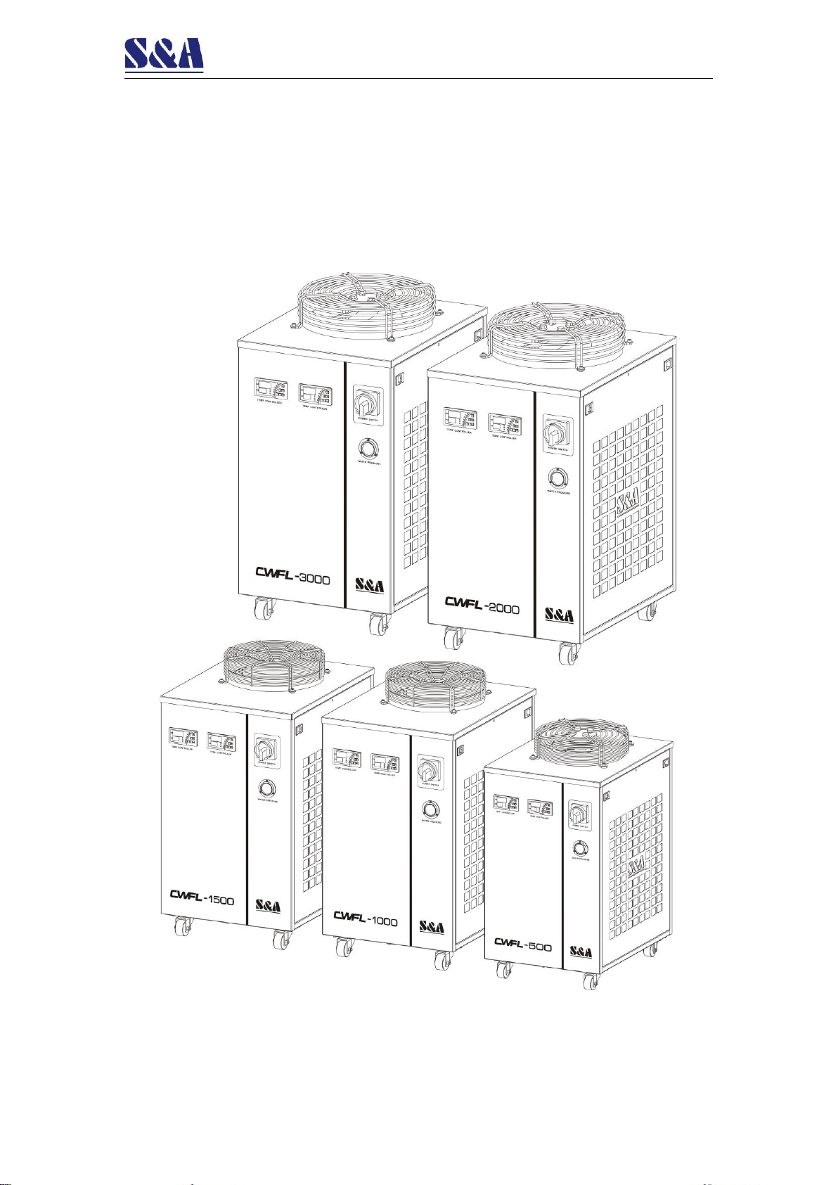
CWFL- 1000 A N
④Water pump
③Electric source type
②Chiller model series
①Chiller application
Note: This model description only contains the description of the company's main product
codes, not all of them are listed. Please confirm with our company before ordering the specific
model, our company has the final interpretation right about it.