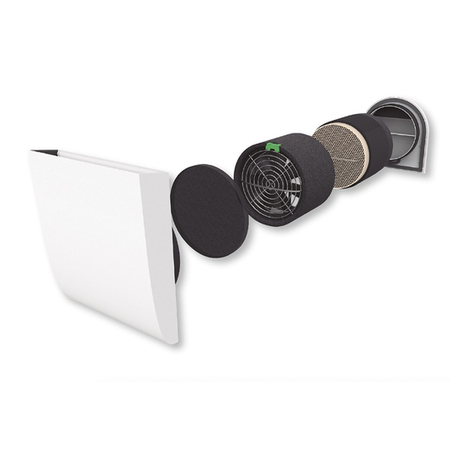
S&P PIV-W User manual

PIV-W
E -100B
EB 50
-2


ÍNDICE
1. Información general
2. Información previa
3. Información técnica
4. Instrucciones de instalación
5. Mantenimiento
ANEXO: Placa electrónica
Contenido del embalaje:
1. PIV W con filtro y batería
2. Kit de fijación (tornillos)
3. Manual de instrucciones
ESPAÑOL
3

1. INFORMACIÓN GENERAL:
1.1 Introducción
Este manual está destinado a la utilización de la Ventilación centralizada por impulsión PIV W.
Tiene por objeto el aportar un máximo de información y de seguridad durante la instalación, la puesta en marcha
y durante la utilización.
Dado que nuestros productos están en constante evolución, Soler & Palau, se reserva el derecho de modificar
este manual sin previo aviso.
1.2 Garantía y responsabilidad civil
Garantía
La PIV W tiene una garantía de dos años a partir de la fecha de compra. Esta garantía incluye el suministro
gratuito de las piezas de recambio.
La garantía no cubre:
Los gastos de montaje y desmontaje.
Las averías que, según Soler & Palau, sean debidas a una mala instalación, manipulación, una negligencia o un
accidente.
Las averías que se presenten después de una manipulación o una reparación realizada por terceras personas
sin la autorización de Soler & Palau.
Para devolver una pieza defectuosa, el usuario debe contactar con su instalador.
Responsabilidad civil
La PIV W está concebida para sistemas de ventilación que permiten la renovación del aire por impulsión en
viviendas unifamiliares. Soler & Palau no es responsable de los daños provocados por:
•Una utilización inapropiada,
•El desgaste normal de los componentes,
•La no observación de las instrucciones de este manual en cuanto a la seguridad, el uso y la puesta en marcha,
•La utilización de piezas no suministradas por Soler & Palau.
1.3 Seguridad
Normas generales de seguridad
La PIV W ha sido diseñada para ser incorporada a un sistema de ventilación por impulsión.
Después de la instalación, no debe haber ningún riesgo en cuanto a la seguridad, la salud y el medioambiente,
de acuerdo con las directrices de la CE. Esto es asimismo válido para el resto de productos utilizados en la
instalación.
Las siguientes advertencias generales son importantes:
Seguir las instrucciones de seguridad con objeto de evitar cualquier daño en los ventiladores y en las personas
Las características técnicas de este manual no pueden ser modificadas.
Los moto ventiladores no pueden ser modificados.
Los moto ventiladores deben ser alimentados con corriente alterna monofásica de 230 V / 50 Hz
Para que la instalación esté en conformidad con las directrices de la CE, el aparato debe estar conectado a la
red eléctrica según las normas vigentes.
El aparato debe estar montado de tal manera que, en condiciones normales de funcionamiento, no exista ningún
riesgo de contacto con las piezas en movimiento y/o bajo tensión eléctrica.
La PIV W cumple con las reglamentaciones relativas a los aparatos eléctricos.
Antes de intervenir en el aparato para cualquier operación, siempre desconéctelo de la alimentación eléctrica.
Utilizar las herramientas adecuadas. Utilizar el aparato únicamente para el uso al que está destinado
4
2. INFORMACIÓN PREVIA:
•Elegir la ubicación del equipo asegurando que el recorrido del conducto no tiene obstáculos:
tuberías, cables, etc.
•No colocar el equipo en el interior del baño.
•Asegurar que la toma de aire está separada al menos 3 metros de la salida de humos de la
caldera (si esta última está por debajo) y 1 metro si está en el lateral o por encima.
•Procurar que la red de conductos sea lo más recta posible.
•Para la red, se deben utilizar conductos rígidos.
•La impulsión de aire deberá estar situada en una posición centrada respecto a la
configuración de la vivienda y lo más alto posible.
•Evitar que la longitud del conducto supere los 10 m.
•Mantenga separado el equipo unos 150 mm de cualquier ventana.
Condiciones de instalación:
Kit de Fijación:
4 PINE TREE CLIPS
4 TORNILLOS
AUTOPERFORANTES
8 REMACHES
MANUALES
1 TAPÓN
5

Características aerodinámicas:
7
0
6
0
5
0
4
0
3
0
2
0
0
1
0
1
0
3
0
50 70 90 110 Q(m3/h
)
DP (Pa)
Características técnicas:
Regulación:
TºC
Posición
ventilador
Caudal
Máx.
Potencia
(W)
Trickle 40 5,7
Medium 55 6,7
Large 70 7,7
Boost 110 10,9
Trickle 55 6,7
Medium 70 7,7
Large 110 10,9
Boost 110 10,9
<19º
(Pos.
ajuste)
>19º
Modelo
Tensión
(V)
Motor
Potencia
máxima.
(W)
Potencia
batería
(W)
Nivel
sonoro
máximo.
(dB(A) à 3m)
Caudal máximo
(m3/h)
PIV W 230 CC 11 500 28 110
3. INFORMACIÓN TÉCNICA:
Boost
Ajuste
6

4. INSTRUCCIONES DE INSTALACIÓN:
Esquema de instalación estándar:
Toma de
aire ext.
Impulsión
PIV W
Vista del equipo:
Toma de aire exterior.
(4 opciones)
Impulsión
a la
vivienda
Interruptor batería
eléctrica (opcional)
Debe incluir una protección de
3 Amperios (no incluida)
Dimensiones:
230 V A.C. –50Hz
Instalación eléctrica externa
7

MONTAJE:
1Elegir la posición deseada del PIV W en función de las consideraciones previamente
indicadas.
2Escoger el lado de aspiración del equipo, izquierdo o derecho, y coloque el panel trasero
según la Figura 1 en función del sentido deseado. La carcasa central (Figura 2) deberá
colocarse según la posición del panel trasero.
Fig 1: Panel trasero indicando el sentido del aire
Fig 2: Carcasa central
Plantilla:
1a Si la toma de aire se realiza por el panel lateral,
utilizar el Panel A (Figura 3) como plantilla asegurando
que la salida del cable quede lo más cerca de la
pared. Marcar en la pared el hueco para la toma de
aire. Asegurarse que quede suficiente espacio
alrededor de la plantilla para la colocación del equipo
y de los paneles.
1b Si la toma de aire se realiza por el lado trasero,
utilizar el conjunto Panel Trasero/Carcasa central
como plantilla. Marcar en la pared el hueco para la
toma de aire. Asegurarse que quede suficiente
espacio alrededor de la plantilla para la colocación del
equipo y de los paneles. (Figura 4)
Fig 3a:
Panel lateral con
salida de cable
Fig 3b:
Panel lateral
Fijación:
1Perforar un agujero de 107 mm en las marcas
realizadas previamente. Si la toma de aire es lateral,
la longitud del conducto será al menos el espesor de
la fachada más 80mm. Si la toma es trasera este
valor será el espesor de la fachada más 15 mm.
2Colocar el conducto en el hueco realizado e instalar
la rejilla exterior. 1 y 4 : Tomas de aire laterales
2 y 3: Tomas de aire traseras
Selección:
Cinta
adhesiva
8

MONTAJE:
3Retirar la cinta adhesiva de seguridad para el transporte
del panel trasero (Figura 1). Presentar el panel trasero a
la carcasa central (Figura 2) asegurándose que las guías
del filtro encajan correctamente.
4Fijar el panel trasero a la carcasa central con 4
dispositivos de fijación rápida suministrados en el kit (Pine
tree clip). En la figura 5 se muestra como ejemplo una
unidad instalada en sentido derecho. Para el lado
izquierdo se colocarán en el lado opuesto.
5Colocar el tapón suministrado en el hueco del panel
frontal de la carcasa central.
6Encajar el conjunto al conducto (incluyendo el panel
lateral en caso de toma de aire lateral). Asegurarse que el
cable sale por el hueco previsto en el panel lateral. Fijar la
unidad mediante los 5 puntos de fijación del panel
trasero.
7Encajar la cara frontal interna alineando los ocho agujeros para los remaches. Fije la cara
frontal y la carcasa central encajando con fuerza la cabeza y el cuerpo del remache. Para
ello introducir el cuerpo del remache en la carcasa y fijar el panel frontal con la cabeza del
remache. Asegurar que el filtro está correctamente colocado.
8Conectar la alimentación a la manguera blanca (3 cables). Se suministra una caja con
fusible de 3 amperios incorporado.
9Conectar el cable de la batería eléctrica (2 hilos) al interruptor incluido.
10 Colocar el embellecedor frontal externo fijándolo por la parte baja y frontal.
Figura 5: Conjunto carcasa / panel
Pine tree Clip
Pine tree Clip
Pine tree Clip
Pine tree Clip
Panel Trasero
Hueco
9

MONTAJE:
Si por la configuración de la vivienda alguna sala queda fuera de la zona de circulación del
aire por la rejilla de impulsión, se puede colocar una T que permita derivar el aire a esta
zona.
Si la unidad no puede estar colocada cerca de la pared exterior y el conducto de conexión
con la toma de aire exterior es suficientemente largo, se recomienda aislar este tramo para
evitar condensaciones en la superficie externa del conducto. Para mejorar su acabado, se
recomienda colocar un embellecedor de conducto.
CONDUCTOS:
Zona fuera de la circulación del
aire
Pasillo Toma
exterior
Pasillo Toma
exterior
PIV W Conducto aislado
PIV
W
10

MONTAJE:
5. MANTENIMIENTO
No se debe manipular el equipo de otra manera de la que se ha mencionado
anteriormente, quedando en caso contrario la garantía cancelada.
El cambio del filtro dependerá de la utilización, pero podrá prolongarse hasta 3 años.
Ajuste del equipo:
Verificar que el equipo funciona correctamente y ajustar la velocidad en función de las
necesidades. Para modificar la velocidad del equipo presionar el botón situado en la parte
superior de la tarjeta electrónica situada en el lateral del equipo:
5. MANTENIMIENTO
Recomendaciones:
El equipo deberá ser instalado por una persona autorizada.
Las conexiones eléctricas deberán ser conformes a las normativas vigentes.
pulsación pulsación
pulsación
pulsación
Contador de horas
Pulsar en continuo para ver
todos los dígitos (de + a -)
Temperatura de
impulsión
11

1 8 ON Programación
2 7 OFF Batería 10ºC
3 6 ON Aumento Qv
4 5 ON Parada >25ºC
Configuración por defecto PIV
¡PELIGRO, TENSIÓN DE
RED!
Asegúrese de proteger sus
manos antes de manipular
los conectores (4 y 7)
5
8
7
2
1
3
4
6
1. Pulsador tiempo discurrido
2. Display tiempo discurrido
3. Leyenda Funciones
4. Puentes Funciones
5. Pulsador velocidades
6. Indicador LED velocidad
7. Tensión de alimentación
8. Indicador LED temperatura
Funciones - En la placa se pueden modificar ciertas funciones
de trabajo modificando los puentes CN4:
Puente 1-8 = Programación. NO TOCAR. (On por defecto)
Puente 2-7 = Temperatura activación de la batería eléctrica.
On - 15ºC. Off - 10ºC (por defecto).
Puente 3-6 = Aumento del 10% del caudal si T > 19ºC.
On - Aumento (por defecto). Off - Sin aumento
Puente 4-5 = Parada si T > 25ºC.
On - Activado (por defecto para el PIV).
Off - Funcionamiento continuo (por defecto para el PIV W).
Contador Tiempo funcionamiento - se contabiliza el número de
horas en funcionamiento hasta 11 años.
Pulsando en continuo el botón podrá ver todos los dígitos de
mayor a menor.
Ajuste Velocidad - 4 opciones: Trickle, Medium, Large y Boost,
indicadas por LEDS: Verde, Amarillo, Naranja y Rojo.
Visor temperatura - sea cual sea la configuración elegida, la temperatura de la toma de aire se
muestra mediante 3 LEDS indicando si T <19ºC (amarillo), >19ºC (naranja), >25ºC (rojo). Si la
temperatura se encuentra en el límite, el LED podría parpadear.
Acceso - Para acceder a la placa se deben extraer los dos tornillos dela cubierta plástica circular.
Para el modelo PIV W se debe desconectar el conducto y retirar la carcasa externa
ANEXO
PLACA ELECTRÓNICA
1 8 ON Programación
2 7 OFF Batería 10ºC
3 6 ON Aumento Qv
4 5 OFF Parada >25ºC
Configuración por defecto PIV W
Productos: PIV, PIV BP y PIV W
12

CONTENTS
1. General information
2. Background
3. Technical information
4. Installation instructions
5. Maintenance
ANNEX: Circuit board
Package contents:
1. PIV W with filter and battery
2. Mounting kit (screws)
3. Instruction manual
ENGLISH
13

1. GENERAL INFORMATION :
1.1 Introduction
This manual is to be used for the PIV W central forced-air ventilation system.
It aims to provide as much information as possible to ensure safe installation, start-up and use.
As our products are constantly evolving, Soler & Palau reserves the right to modify this manual with no prior
notice.
1.2 Warranty and legal liability
Warranty
The PIV W comes with a two-year warranty from the date of purchase. This warranty covers replacement parts.
The warranty does not cover:
Mounting and unmounting expenses.
Any damage that Soler & Palau deems to be due to improper installation or use, negligence or accident.
Any damage that appears after the equipment has been repaired or handled by third parties without the express
authorization of Soler & Palau.
To return defective parts, users must contact their installer.
Legal liability
PIV W is designed for forced-air ventilation systems in single-family homes. Soler & Palau will not be held
responsible for damage caused by:
•Improper use
•Normal wear and tear
•Failure to follow the instructions in this manual regarding safety, use and installation
•Use of parts not provided by Soler & Palau.
1.3 Safety
General safety guidelines
PIV W has been designed to be used in a forced-air ventilation system.
After installation, it should pose no risks in terms of safety, health or the environment, in line with CE directives.
This is also true of the rest of the products used in the installation.
It is important to keep in mind the following general safety guidelines:
Follow all safety instructions in order to avoid any damage to the ventilation system or personal injury
The technical specifications in this manual may not be modified.
The motor fans may not be modified.
The motor fans must use single-phase alternating current at 230 V / 50 Hz.
For installation to comply with CE standards, the device must be connected to the power grid in accordance with
current regulations.
The device must be assembled in a way that ensures there is no risk of contact between the moving and/or live
parts under normal circumstances.
PIV W meets all standards applicable to electric devices.
Before handling the device in any way, always disconnect it from the power source.
Use the right tools.
Only use the device for its intended purpose.
14

2. BACKGROUND:
•Choose the best location for the device, making sure there are no obstacles for running the
ducts: pipes, cables, etc.
•Don’t install the device inside a bathroom.
•Make sure the air intake is at least 3 meters from the hot-water heater smoke outlet if the
latter is below and 1 meter if it is on the side or above.
•Try to keep the ducting network as straight as possible.
•For the network, use rigid ducts.
•The air supply must be located in a central position with regard to the distribution of the
home and as high as possible.
•Avoid ducts over 10 m long.
•Makes sure the device is at least 150 mm away from any window.
Installation conditions:
Mounting kit:
15

Aerodynamic specifications:
7
0
6
0
5
0
4
0
3
0
2
0
0
1
0
1
0
3
0
50 70 90 110 Q(m3/h
)
DP (Pa)
Technical characteristics:
Regulation:
TºC Fa n position
Max
ai rflow
Power (W)
Trickl e 40 5.7
Medium 55 6.7
Large 70 7.7
Boos t 110 10.9
Trickl e 55 6.7
Medium 70 7.7
Large 110 10.9
Boos t 110 10.9
<19º
(Adjus t
posi tion)
>19º
Model
Voltage
(V)
Motor
Max power
(W)
Battery
power (W)
Max s ound
level (dB(A) at
3m)
Max ai rflow
(m3/h)
PIV W 230 CC 11 500 28 110
3. TECHNICAL INFORMATION:
Boost
Adjust
16

4. INSTALLATION INSTRUCTIONS:
Standard installation diagram:
Ext. air
intake
Air flow
PIV W
View of device:
Ext. air intake
(4 options)
Air flow
into home
Electric battery
switch (optional)
Must include 3-Amp protection
(not included)
Dimensions:
230 V A.C. –50Hz
Ext. electric installation
17

ASSEMBLY:
1Choose the location for the PIV W with the aforementioned conditions in mind.
2Choose which side of the device the intake will be on, right or left, and assemble the rear
panel following figure 1 for the chosen direction. The central housing (figure 2) must be
assembled depending on the position of the back panel.
Fig 1: Back panel indicating direction of air flow
Fig 2: Central housing
Guide:
1a If the air intake is through the side panel, use Panel
A (figure 3) as a guide, making sure the cable outlet is
as close as possible to the wall. Make sure there is
enough space around the guide to install the device
and the panels.
1b If the air intake is through the rear, use the Back
Panel / Central Housing combination as a guide.
Mark the location of the hole for the air intake on the
wall. Make sure there is enough space around the
guide to install the device and the panels (figure 4). Fig 3a:
Side panel with
cable outlet
Fig 3b:
Side panel
Mounting:
1Cut a 107 mm hole on the marks made before. If
the air intake is on the side, the duct must be at least
as long as the thickness of the façade plus 80 mm. If
it is in the rear, it must be the thickness of the façade
plus 15 mm.
2Put the duct through the hole and assemble the rear
grille. 1 and 4 : Side air intake
2 and 3: Rear air intake
Location:
Adhesive
tape
18

ASSEMBLY:
3Remove the adhesive security tape for transport from
the back panel (figure 1). Introduce the back panel into
the central housing (figure 2) making sure the filter guides
fit together correctly.
4Attach the back panel to the central housing with the 4
pine trees provided. Figure 5 shows an example of a unit
installed on the right. For left-side installation, do it on the
other side.
5Put the plug provided into the space in the front panel of
the central housing.
6Fit the device onto the duct (including the side panel for
side air supply). Make sure the cable runs out of the
space provided in the side panel. Mount the unit using the
5 points on the back panel.
7Fit the internal front panel by aligning the eight rivet holes. Attach the front panel to the
central housing by snapping the rivets into place. To do so, put the body of the rivet into the
housing and fix the front panel in place with the head of the rivet. Make sure the filter is
properly in place.
8Connect the white tube to the power source (3 cables). An incorporated 3-Amp fuse box is
provided.
9Connect the battery cable (2 wires) to the switch provided.
10 Attach the external front facing panel on the lower front edge.
Figure 5: Panel / housing
Pine tree
Pine tree
Pine tree
Pine tree
Back panel
Space
19

ASSEMBLY:
If any rooms are beyond the air circulation area for the forced-air grille, given the distribution
of the home, a T junction may be installed to send air to that area.
If the unit can’t be mounted near an exterior wall and the duct connection to the exterior air
supply is long enough, we recommend insulating this section to avoid condensation along
the outer surface of the duct. To improve the finish, a duct cover is recommended.
DUCTS:
Zona fuera de la circulación del
aire
Hallway Ext.
intake
Hallway Ext.
intake
PIV W Insulated duct
PIV
W
20
Table of contents
Languages:
Other S&P Ventilation Hood manuals

S&P
S&P TD EVO 100 User manual

S&P
S&P EBB-250 NS User manual

S&P
S&P EBB-250 NHT User manual

S&P
S&P VA Series User manual

S&P
S&P EBB-100 NHT User manual

S&P
S&P HCM-150N User manual

S&P
S&P SILENT CHZ Series User manual

S&P
S&P HP 60 N User manual

S&P
S&P GET-60 NF PLUS Operator's manual

S&P
S&P NEMBUS 210 User manual
Popular Ventilation Hood manuals by other brands

Pkm
Pkm BS36-60AIXPH instruction manual

Witt
Witt Piper W Operation and installation manual

Faber
Faber BREVA PRO 11 installation instructions

ROBLIN
ROBLIN Lido / 2 Centrale Instructions for use and installation

Zephyr
Zephyr Tornado II Use, care and installation guide

Broan
Broan BKSJ130WW Installation use and care manual