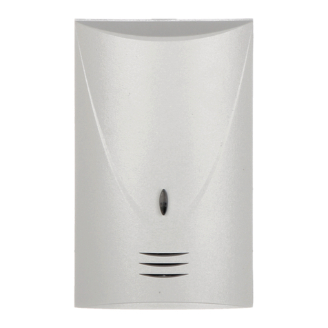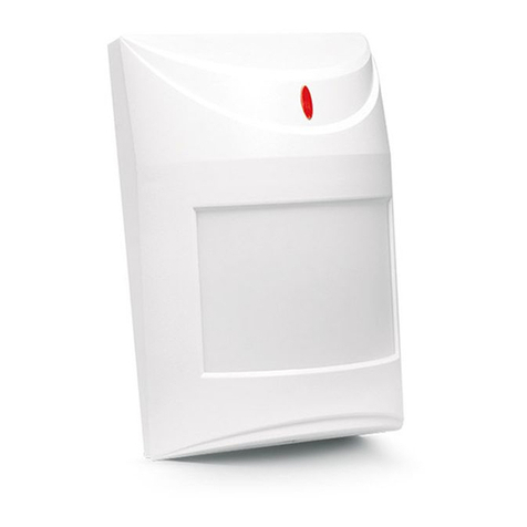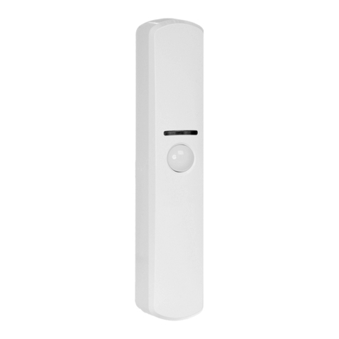
When in the microwave counting mode (MW), the detector will generate an alarm both
in the above mentioned case, upon detection of a motion by both systems, as well as
after 16 excitations of the microwave sensor, with no violation of the PIR sensor.
NOTE: Remember to set an appropriate sensitivity of microwave channel
detection, since the microwaves are capable of penetrating, for example,
through gypsum walls, doors, etc., which may cause generation of false
alarms.
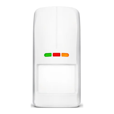
The LED allows the installer to check the detector for correct functioning and to
approximately determine the protected area:
-the LED lights red– alarm,
-the LED lights green – excitation of PIR or MW system.
For 30 seconds after the power is turned on, the detector remains in a starting state,
which is signalized by a rapid blinking of the LED, alternately, green and red. Only then
the detector enters its operational readiness state.
The detector monitors the supply voltage. If the voltage drops below 9V (±5%) for more
than 2 seconds, the detector will signalize a violation state until a voltage of minimum 9V
(±5%) is restored.
INSTALLATION
The detector is designed for indoor installation. It can be mounted on the wall, either
directly or on the included holder.
Prior to installation of the detector housing, remove the electronics board and brake out
adequate openings for screws and cable in the rear panel of the housing.
It is advisable that you exercise particular care to prevent the pyro element from
getting dirty or damaged during installation.
Figure 2 shows typical examples of connecting the detectors in EOL (parameter)
configuration and 2EOL (two-parameter) configuration. Resistors should be mounted
inside the detector housing.
Figure 2. Example of connecting dual detectors
TMP TMP COM 12V NC NC
COBALT dual detector
2R
WRN WRN TMP TMP COM 12V NC NC
COBALT Plus /
COBALT Pro
dual detector
R R
Z2 & Z7 - programmed as „24h TAMPER” – NC type
+12V Z1 COM Z2 Z3 COM Z4 COM Z5 Z6 COM Z7 Z8 COM Z9 Z10 COM Z11 Z12
