SATO WS408TT User manual

WS4 TT Series Printer
Service Manual
WS408TT / WS412TT
W
WS4-TT-r02-17-02-17SM
© 2017 SATO Corporation. All rights reserved.

i
Contents
1Introduction................................................................................................................................ 1
1.1 About This Manual ............................................................................................................ 1
1.2 Warnings and Cautions..................................................................................................... 1
2Maintenance............................................................................................................................... 2
2.1 Print Head Maintenance.................................................................................................... 2
3Spare Parts List ......................................................................................................................... 3
4Spare Parts Removal and Assembly........................................................................................ 9
4.1 Top Cover........................................................................................................................... 9
4.2 Platen Roller and Front Cover.........................................................................................11
4.3 Main Board and Bottom Cover....................................................................................... 12
4.4 Mid Cover......................................................................................................................... 14
4.5 Motor ................................................................................................................................ 15
4.6 Sensors............................................................................................................................ 17
4.7 TPH................................................................................................................................... 18
5Printer Status and Interface Connection ............................................................................... 19
5.1 Printer Status Indication................................................................................................. 19
5.2 Printer Connector Pin Assignment................................................................................ 20

1
1 Introduction
1.1 About This Manual
This service manual gives the information necessary for you to adjust and repair the WS4 TT printer. This
service manual is written only for SATO authorized service personnel. The information in this manual is
confidential to general users.
This service manual is used as an extension of the operator manual. For basic specification, Installation,
operation and configurations of the printer, refer to the operator manual of the WS4 TT printer.
1.2 Warnings and Cautions
Before doing maintenance, please notice the followings:
Put the device in a safe place.
Please keep the device in a clean and dry the area.
WARNING
When replace or install any parts, please check following:
Turn off power.
Disconnect the power cord of the AC Adapter.
Disconnect the USB cable.
CAUTION (Static Discharge)
The printer electronics are sensitive to static discharge.
Wear an anti-static wristband and attach it to the printer chassis.
CAUTION (Replace Parts)
Please do not wear jewelry.
Please do not get wet on hands and parts.
2
2 Maintenance
2.1 Print Head Maintenance
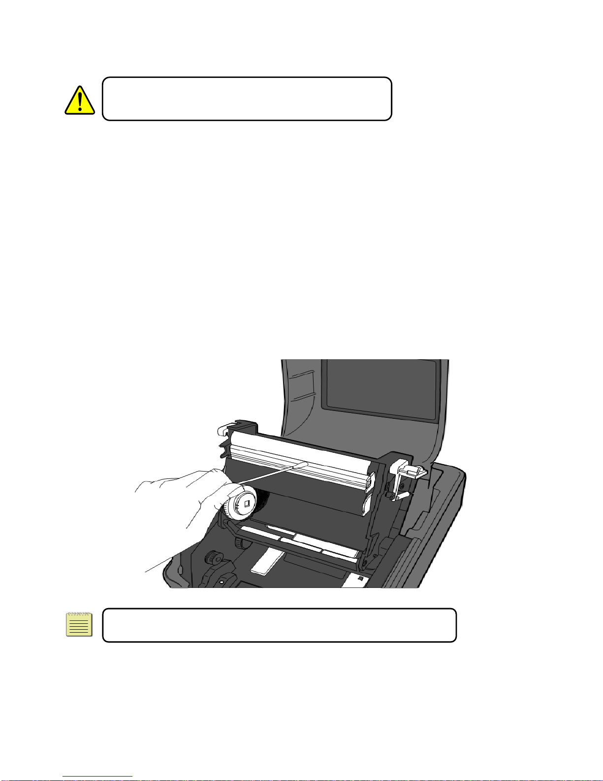
Warning: Always turn off the printer before cleaning.
It is essential to keep print head clean if you want the best printing quality. We strongly recommend that
you clean the print head when loading a new media roll. If the printer is operated in critical environment or
the print quality declines, you need to clean the print head more frequently.
Keep in mind these things before you clean TPH:
Keep the water away in case of corrosion on heating elements.
If you just finish printing, wait until the print head cools down.
Do not touch the print head with bare hands or hard objects.
Cleaning Steps:
1. Moisten a soft cloth or a cotton swab with ethyl alcohol.
2. Gently wipe the print head in one direction. That is, wipe it only from left to right or vice versa. Do not
wipe back-and-forth, in case dust or dirt attaches to the print head again.
Note: Print head warranty becomes void if print head’s serial number is
removed, altered, defected, or made illegible, under any circumstance.

3
3 Spare Parts List
Parts Number
Description
Picture
WT205-001
PRINT HEAD (203dpi) WS408TT
WT301-001
PRINT HEAD (300dpi) WS412TT
59-WT2A1-001
RIBBON-ADAPTERS-WS4TT
59-WT2A2-001
ASSY-PLATEN-WS4TT
59-WT2A3-001
ASSY-MAIN-PCBA-WS4-LAN
(USB + LAN)
59-WT2A3-011
ASSY-MAIN-PCBA-WS4-STD
(USB + LAN + RS232C)
4
Parts Number
Description
Picture
59-WT2A4-001
ASSY-SENSORS-WS4TT
59-WT2A5-001
ASSY-MOTOR-WS4TT
59-WT2A6-001
SW-PSU-WS4TT-N
59-WT2A7-001
ASSY-PANEL-PCBA-WS4TT
59-WT2A8-001
HRNS-PRINT-HEAD-WS4TT
59-WT2A9-001
GEARS-WS4TT
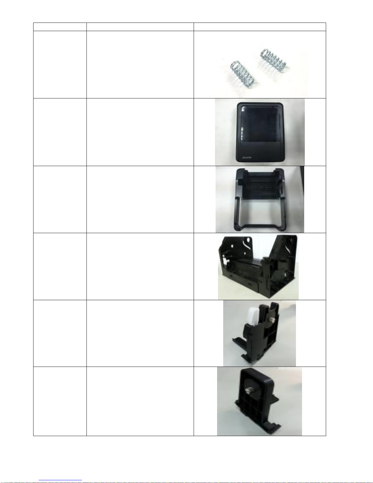
5
Parts Number
Description
Picture
59-WT2B2-001
SPRING-PRINT-HEAD-WS4TT
59-WT2B3-001
ASSY-TOP-COVER-WS4TT
59-WT2B4-001
MID-COVER-WS4TT
59-WT2B5-001
PRINTER-FRAME-WS4TT
59-WT2B6-001
ASSY-MEDIA-HLDR-R-WS4TT
59-WT2B7-001
ASSY-MEDIA-HLDR-L-WS4TT
6
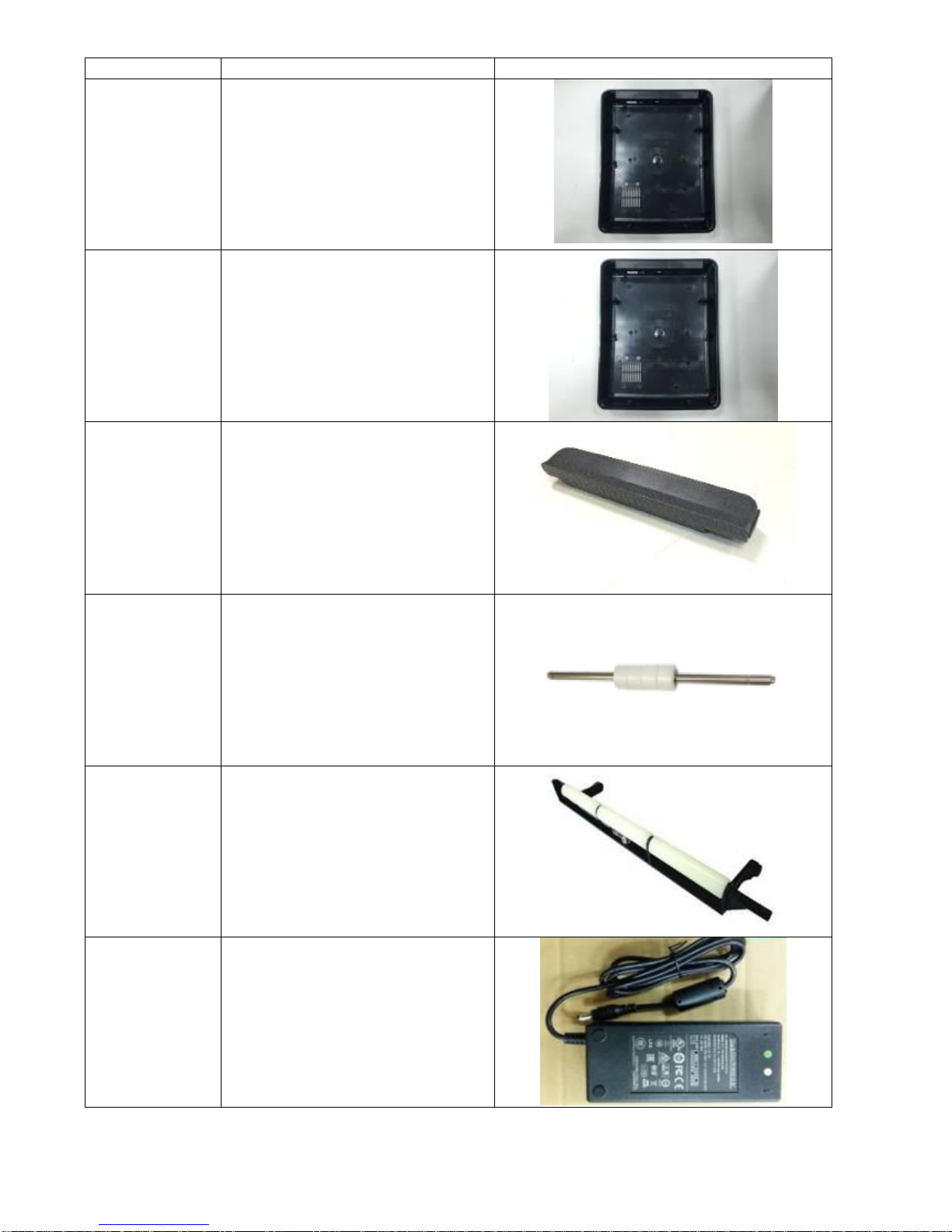
Parts Number
Description
Picture
59-WT2B8-001
BOTTOM-COVER-WS4TT-LAN
59-WT2B8-011
BOTTOM-COVER-WS4TT-STD
59-WT2B9-001
FRONT-COVER-WS4TT
59-WT2C2-001
ASSY-MEDIA-ROLLER-WS4TT
59-WT2C4-001
ASSY-GUIDE-ROLLER-WS4TT
59-WT2A6-011
SW-PSU-WS4TT-N-EX1

7
Parts Number
Description
Picture
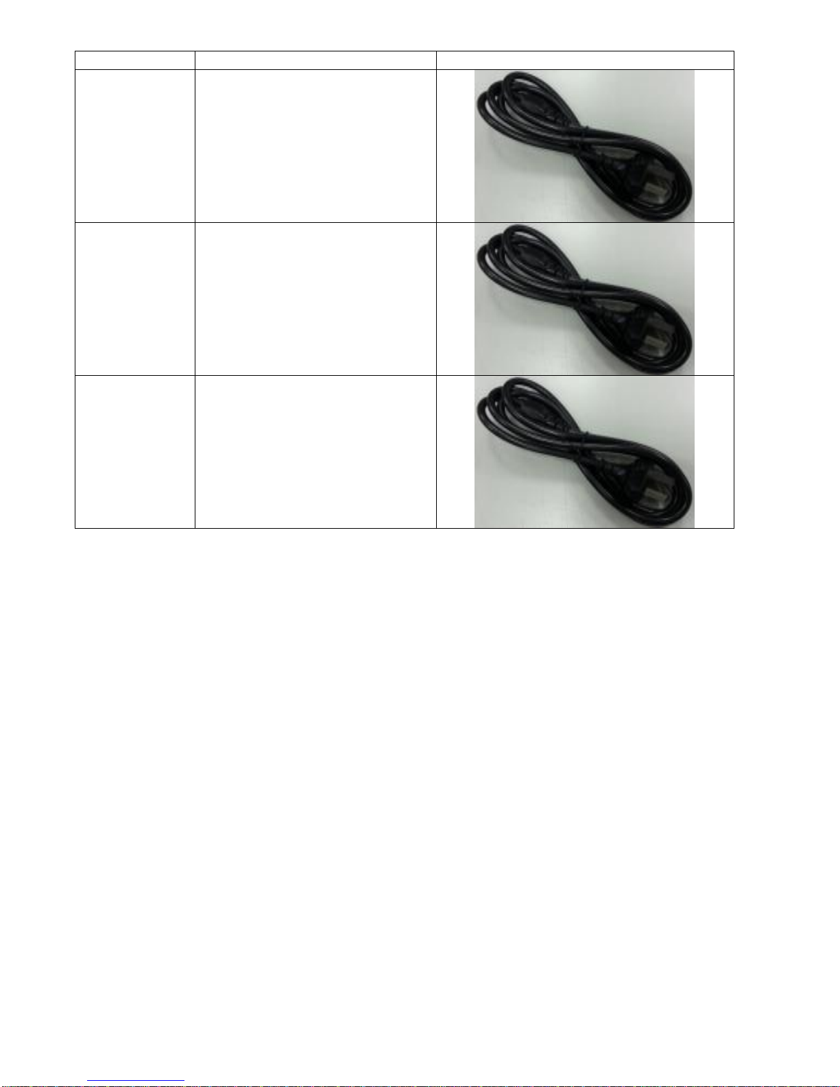
59-WT2C3-001
POWER-CORD-WS4TT-CN
59-WT2C3-061
POWER-CORD-WS4TT-EX1
59-WT2C3-031
POWER-CORD-WS4TT-EU
(For EU, VN-NESIA and KR Area Code)
59-WT2C3-011
POWER-CORD-WS4TT-UK
(For UK, SP and MYArea Code)
59-WT2C3-021
POWER-CORD-WS4TT-TH
59-WT2C3-041
POWER-CORD-WS4TT-IND
8
Parts Number
Description
Picture
59-WT2C3-051
POWER-CORD-WS4TT-PA
59-WT2C3-071
POWER-CORD-WS4TT-BR
59-WT2C3-081
POWER-CORD-WS4TT-AR
9
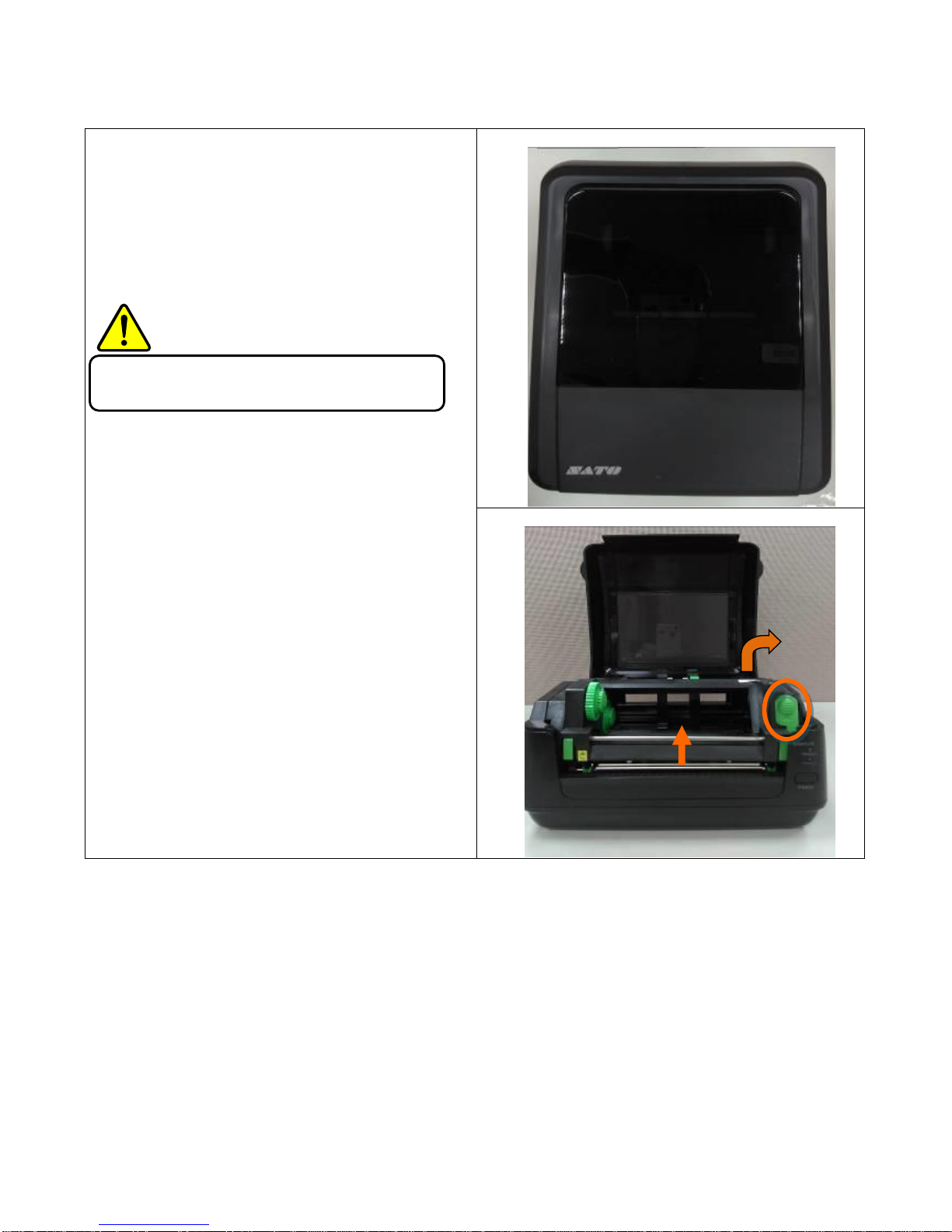
4 Spare Parts Removal and Assembly
4.1 Top Cover
1Open the top cover. (Figure A-1)
2Take off the top cover and push the right latch
in orange and lifting the TPH module upward.
(Figure A-2)
3Then we can see the TPH and the platen roller
in orange. (Figure A-3)
Warning:
Always turn off printer power before removal.
A-1
A-2

10
A-3
11
4.2 Platen Roller and Front Cover.
Platen Roller
1. From upside of the printer, use screwdriver
to loosen 6 screws which are marked in
orange. Then we can take off the front
cover. (Figure B-1)
2. When we face to the printer ,taking out the
left and right bushing which are marked in
orange, then we could take out the platen
roller. (Figure B-2)
Warning:
Always turn off printer power before removal.
B-1
B-2
12
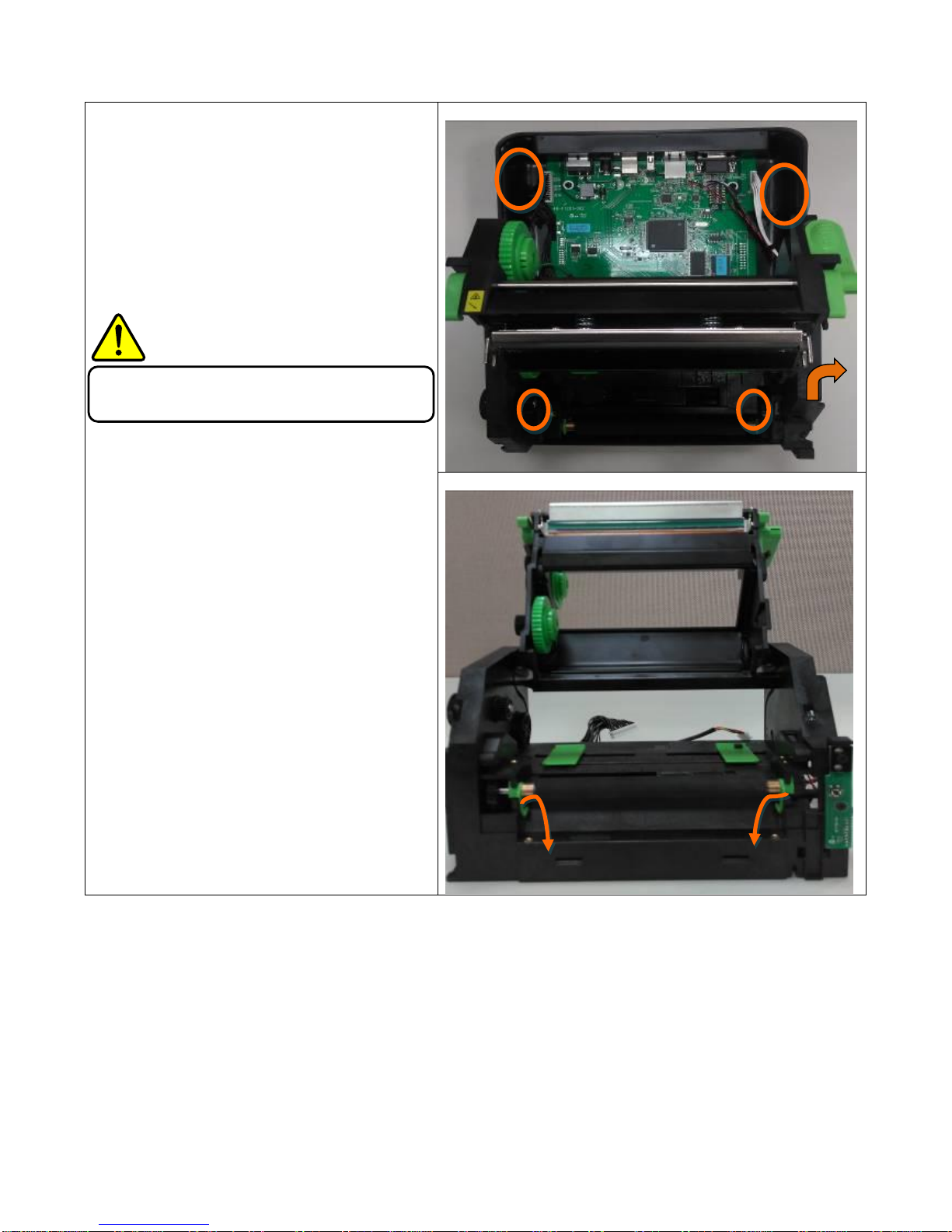
4.3 Main Board and Bottom Cover
1. After taking off top, mid and front cover, we
can see Main Board connect with cable and
Bottom Cover from backside of the printer.
(Figure C-1)
2. Disconnect all cables from MB then lift up and
separate the whole printer module. (Figure C-2)
3. Using screwdriver to loosen 4 screws which are
marked in orange. Then the main board and
bottom cover could be separated. (Figure C-3)
Warning:
Always turn off printer power before removal.
Caution:
When disconnect the power cord, please wait 10
seconds after removing any connectors from the
printer.
C-1
C-2

13
C-3

14
4.4 Mid Cover
1. From upside of the printer, use screwdriver
to loosen 6 screws which are marked in
orange. Then we can take out the front cover
first. (Figure D-1)
2. Secondly, from broadside to pull the mid
cover upward and take it out. (Figure D-2)
Warning:
Always turn off printer power before
removal.
Before replacing TPH, please wait for the
printer head temperature to cool.
D-1
D-2
15
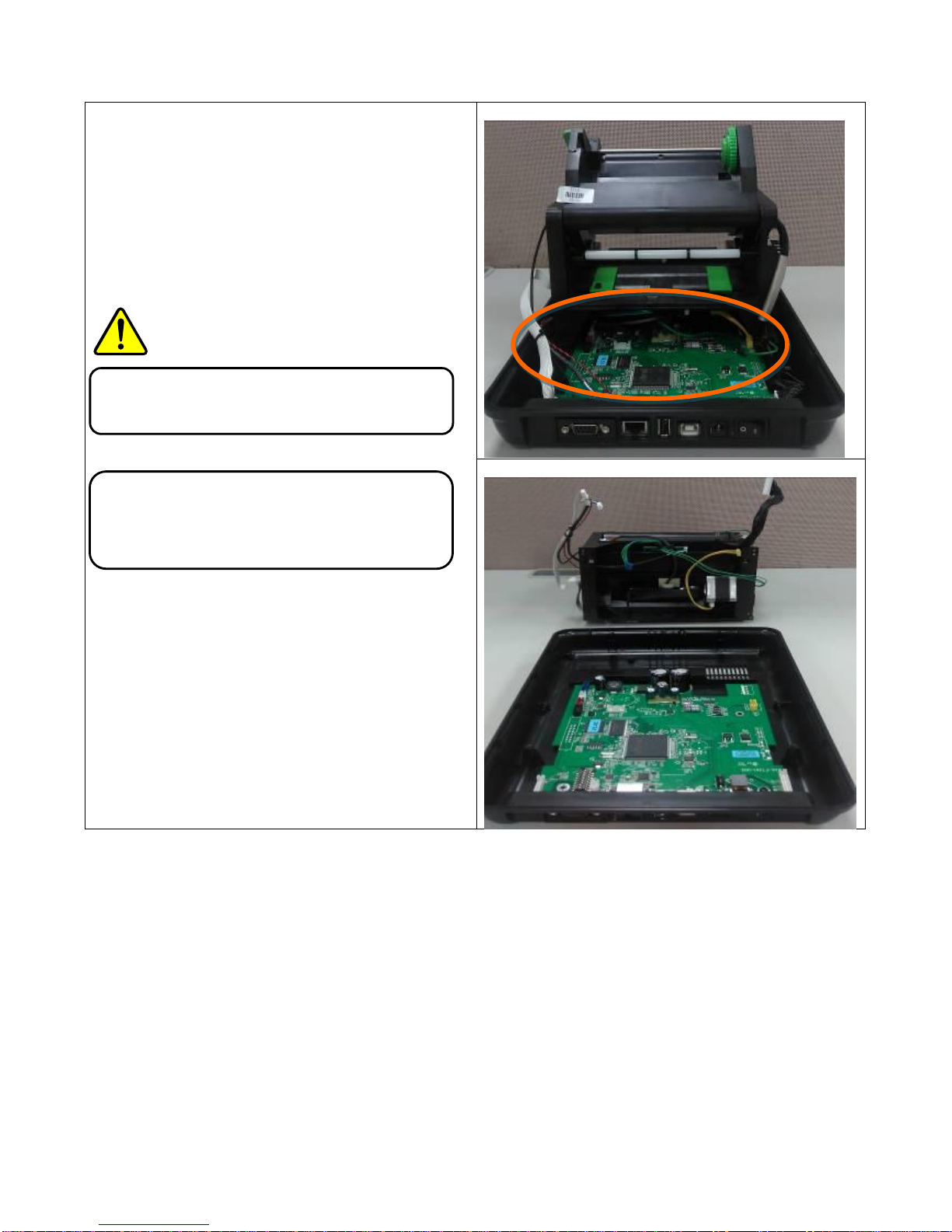
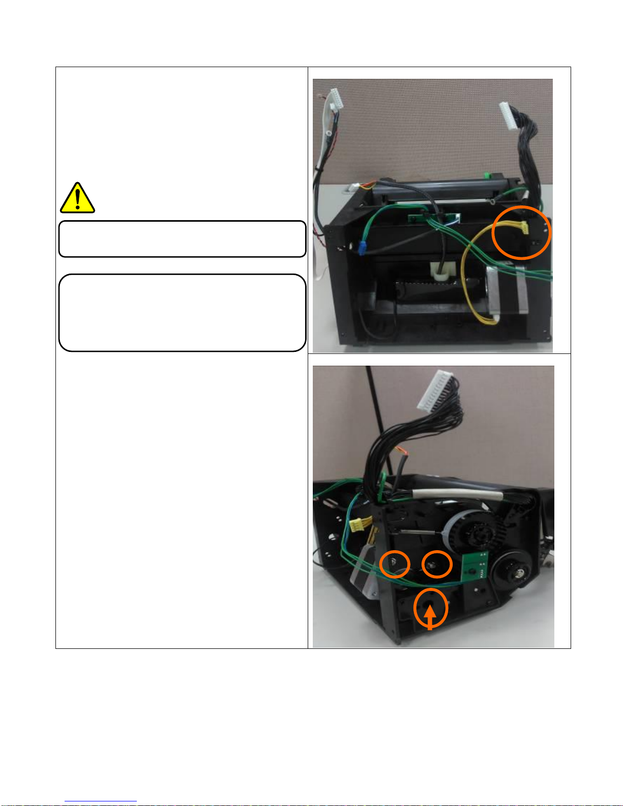
4.5 Motor
1. Separate the whole printer module with main
board and disconnect the cable which is
marked in orange.(Figure E-1)
2. Using screwdriver to loosen 3 screws which
are marked in orange. (Figure E-2)
3. Then we can take the motor out as shown in
Figure E-3.
Warning:
Always turn off printer power before removal.
Caution:
When disconnect the power cord, please wait
10 seconds after removing any connectors
from the printer.
Wait for the motor temperature to cool.
E-1
E-2

16
E-3

17
4.6 Sensors
Transmissive Sensor
1. After taking out the whole printer module and
separating the motor with it ,we can see the
Transmissive Sensor and Reflective Sensor
which are marked in orange. (Figure F-1)
Reflective Sensor
1. After taking out the Reflective Film, then we
can see the Reflective Sensor which is marked
in orange. (Figure F-2)
F-1
F-2

18
4.7 TPH
1. Push and pull down TPH itself in order to
separate with the latch which is marked in
orange. (Figure G-1)
2. Pull the TPH out and loosen 2 screws
which are marked in orange. ( Figure G-2)
3. Disconnect the two cables which are
marked in orange to take the TPH out.
(Figure G-2)
Warning:
Always turn off printer power before
removal.
Before replacing TPH, please wait for the
printer head temperature to cool.
G-1
G-2
Other manuals for WS408TT
1
This manual suits for next models
1
Table of contents
Other SATO Printer manuals

SATO
SATO WS408DT User manual

SATO
SATO CG4 Series User manual

SATO
SATO HR2 Series User manual

SATO
SATO S8408 Standard User manual

SATO
SATO WS208 User manual

SATO
SATO CL4NX Plus User manual

SATO
SATO M8485S User manual

SATO
SATO M-5900RV Use and care manual

SATO
SATO CL408e User manual

SATO
SATO M-84Pro Series User manual

SATO
SATO ARGOX OS-200 Series User manual

SATO
SATO MB410i User manual

SATO
SATO CL608e Guide

SATO
SATO WS408DT User manual

SATO
SATO M-8400RVe Series User manual

SATO
SATO CS-9018 User manual

SATO
SATO CL408e User manual

SATO
SATO MB200/201i User manual

SATO
SATO CL-408 Use and care manual

SATO
SATO LM408e User manual


