SATO D508 User manual
Service Manual
For printer model:
MB400i / MB410i
www.satoamerica.com
PN: 9001193
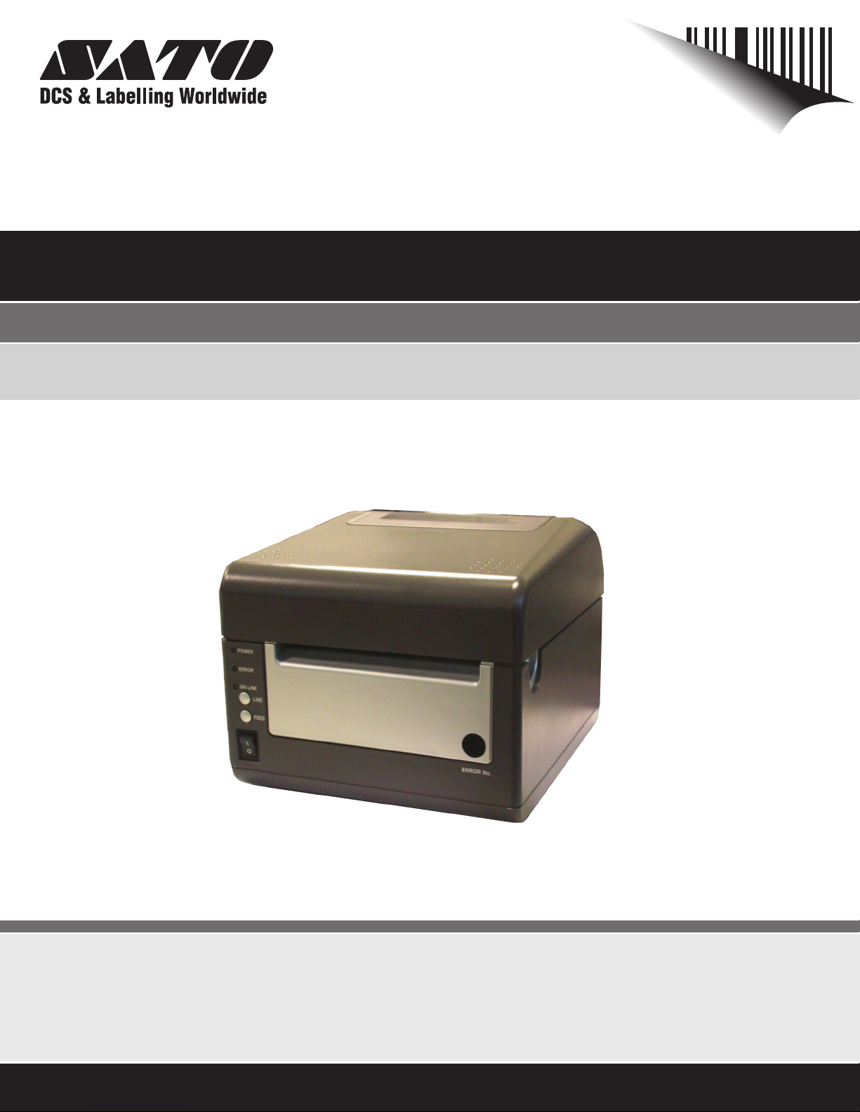
Operator Manual
For printer model:
D508 / D512
www.satoamerica.com
PN: 9001177B

PN: 9001177B
SATO America, Inc.
10350A Nations Ford Road
Charlotte, NC 28273
Main Phone: (704) 644.1650
Technical Support: (704) 644.1660
Technical Support Fax: (704) 644.1661
E-Mail: satosale[email protected]
techsupport@satoamerica.com
www.satoamerica.com
Copyright 2008 SATO America, Inc. All rights reserved
WARNING
THE EQUIPMENT REFERENCED IN THIS DOCUMENT COMPLIES WITH THE REQUIREMENTS IN PART 15 OF FCC
RULES FOR A CLASS B COMPUTING DEVICE. OPERATION OF THIS EQUIPMENT IN A RESIDENTIAL AREA MAY
CAUSE UNACCEPTABLE INTERFERENCE TO RADIO AND TV RECEPTION.

i
TABLE OF CONTENTS
OVERVIEW
1.1 Introduction .......................................................................................................... 1-2
INSTALLATION
Safety Precautions..................................................................................................... 2-2
2.1 Unpacking............................................................................................................. 2-4
2.1.1 Printer Part Names........................................................................................... 2-5
2.1.1 SETTING UP THE PRINTER ............................................................................. 2-6
2.2 Loading Media..................................................................................................... 2-7
2.3 Label Sensing....................................................................................................... 2-9
CONFIGURATION AND OPERATION
3.1 Operating PANEL ................................................................................................. 3-1
3.2 THE REAR PANEL ............................................................................................... 3-2
3.3 THE CONFIGURATION PANEL ........................................................................... 3-3
Switch 4: Unused ....................................................................................................... 3-4
Switch 5: Head Check................................................................................................ 3-5
Switch 6: VR1 Potentiometer Adjustment mode..................................................... 3-5
3.4 Error Codes .......................................................................................................... 3-7
3.5 Offsets................................................................................................................... 3-8
3.6 Potentiometer Adjustments ................................................................................ 3-9
3.6 Potentiometer Adjustments (Cont’d) ................................................................. 3-10
3.7 DATA Dump Diagnostic Label ............................................................................ 3-11
3.8 Printing Test Labels............................................................................................. 3-12
3.9 Printing Factory/Service Test Prints .................................................................. 3-13
CLEANING AND MAINTENANCE
4.1 Introduction .......................................................................................................... 4-1
4.2 Adjusting the Print Quality.................................................................................. 4-1
4.3 CLEANING THE PRINT HEAD, PLATEN AND ROLLERS.................................. 4-2
4.4 Releasing/Replacing the Print Head ................................................................. 4-4
4.4 Cleaning the Sensor ........................................................................................... 4-5
INTERFACE SPECIFICATIONS
5.1 Interface types...................................................................................................... 5-1
5.2 The Receive Buffer .............................................................................................. 5-2
5.3 IEEE1284 Parallel Interface ................................................................................. 5-4
5.4 RS-232C Interface ................................................................................................ 5-5
5.4.1 RS-232C Interface Signals ............................................................................... 5-6
5.5 Universal Serial Bus Interface ............................................................................ 5-7

ii
5.6 Local Area Network Interface..............................................................................5-7
5.7 WIRELESS LAN INTERFACE (802.11 b/g)..........................................................5-8
TROUBLESHOOTING
6.1 Initial Checklist .....................................................................................................6-1
6.2 Checking the IEEE1284 Parallel Interface..........................................................6-1
6.3 Error Signals.........................................................................................................6-5
6.3 Checking the 802.11G Wireless Interface ..........................................................6-6
SATO CONTACTS
SATO Group of companies .......................................................................................7-2

Section 1: Introduction
SATO D508/D512 Operator Manual Page 1-1
1
OVERVIEW
Thank you for your investment in this SATO printer product.
This Operator’s Manual contains basic information about the installation, setup,
configuration, operation and maintenance of the printer.
A total of seven topics are covered herein, and they are organized as follows:
Section 1: Introduction
Section 2: Installation
Section 3: Configuration and Operation
Section 4: Cleaning and Maintenance
Section 5: Interface Specifications
Section 6: Troubleshooting
It is recommended that you become familiar with each section before installing and maintaining
the printer. Refer to the Table Of Contents at the front of this manual to search for the relevant
information needed. All page numbers in this manual consist of a section number followed by the
page number within the stated section.
Note:
All information herein was correct and current at the time of publication. The contents of this doc-
ument are subject to revision and change without prior notification to users. To obtain the most
current version of this document, refer to the SATO America website at www.satoamerica.com.

Section 1: Introduction
Page 1-2 SATO D508/D512 Operator Manual
1.1 INTRODUCTION
The SATO D508/D512 Printer Operator Manual provides information for installing and
maintaining D508/D512 Direct Thermal printers. It is recommended that you become familiar with
each section in this manual before installing and maintaining the printer.
The major difference in the D508 and the D512 printers is the resolution of the print head. The
D508 with its 203 dpi head provides an economical labeling solution for most applications. The
D512's higher 305 dpi resolution provides greater detail for graphics and small point size text.
The D5 Series printers use a subset of the standard SATO Command Language. The D508 and
D512 share the same command set, the only differences are the allowable values representing
the print positions on the label. These values are specified in "dots" and will vary depending upon
the resolution of the printer and the amount of memory available for imaging the label. The allow-
able range for each printer is specified in a table for those command codes. In addition, users
can choose an interface—such as parallel (IEEE1284), serial (RS-232C), Ethernet (10/100-
BaseT), USB 1.1and Wireless LAN IEEE 802.11b.
The following general information is presented in this section:
• General Printer Specifications
Section 1: Introduction
SATO D508/D512 Operator Manual Page 1-3
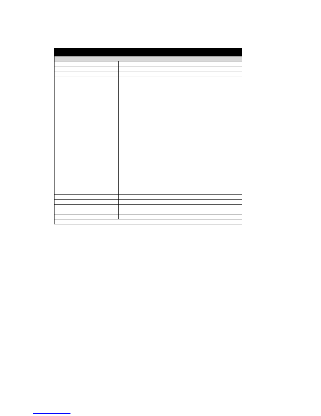
1.1 GENERAL PRINTER SPECIFICATIONS
Attribute
PRINT
Print Method Direct Thermal
CPU 32-bit RISC processor
Printer Command Language SATO (SBPL) and PCL5e Subset
Font / Symbologies
Font
Linear Barcode
2-D Barcode
Font
Linear Barcode
2-D Barcode
SATO Printer Command Language (for 203 dpi and 305 dpi):
U, S, M, WB, XS, XU, XM, XB, XL, OUTLINE, OCR-A, OCR-B,
WL, CG Times, CG Triumvirate
UPC-A, UPC-E, EAN-8, EAN13, Code 39, Code 93, Code 128,
Codabar, MSI, Bookland, Industrial 2/5, Interleaved 2/5, Matrix 2/5,
Postnet, UCC/EAN 128, RSS Composite Code
PDF417, Micro PDF417, Truncated PDF417, Maxicode, Data matrix,
QR Code
PCL5e Subset (Optional for 305 dpi only):
CG Triumvirate Bold Condensed Bold, Univers Medium, Univers Bold,
Courier Regular, OCR-A, OCR-B, Roman Pillar Regular, Roman Pillar
Bold, Roman Pillar Italic, Roman Pillar Bold Italic (supports Universal
Font Scaling Technology Ver. 4.1)
UPC-A, UPC-E, EAN-8, EAN13, Code39, Cjode 93, Code 128, MSI,
Bookland, Indusstrial 2/5, Interleaved 2/5, Matrix 2/5, Postnet, UCC/
EAN 128
PDF417, Maxicode
Font Memory 4 MB
Print Head Resolution 8 dots per mm for 203 dpi | 12 dots per mm for 305 dpi
Print Speed For D508: 6 ips (150 mm/second)
For D512: 4 ips (100 mm/second)
Max. Print Area 4.1” (104 mm) W by 15.7” (400 mm) L
Section 1: Introduction
Page 1-4 SATO D508/D512 Operator Manual
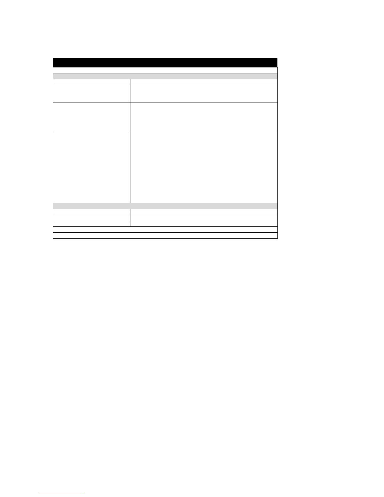
1.1 GENERAL SPECIFICATIONS (CONT’D)
Attribute
MEDIA
Media Type Roll and fanfold
Label Thickness
(Label + backing paper)
0.0026” (0.6 mm*) - 0.007” (* 0.19 mm)
*Check with your dealer regarding conditions
for using thin 0.002” (06 mm) labels
Label Form Roll Label: Maximum outer diameter of 4.33” (110 mm) face out
Core Inner Diameter of 1.5” (40 mm)
Outer Diameter: 4.33” (110 mm)
Fan-fold label: Max. foldable height: 3.94” (100 mm) loaded externally)
Wind Orientation: Face-out
Label Size (adhesive labels) Width for all types:
1.1” (28 mm) - 4.65” (118 mm)
For continuous feed:
Length: 0.71” (18 mm) - 15.75” (400 mm)
For Cutter usage (optional):
Length: 1.1” (23 mm) - 15.75” (400 mm)
For Tear Off mode:
Length: 0.71” (18 mm) - 15.75” ( 400 mm)
SENSING
See-Through For die-cut label with gap: Fixed, 0.25" (6.3 mm) from left label edge
Continuous Form Sensor not used
Eye Mark Reflective sensor (for use with Pre-printed eye marks)
*All specifications subject to change without notice.
Section 1: Introduction
SATO D508/D512 Operator Manual Page 1-5
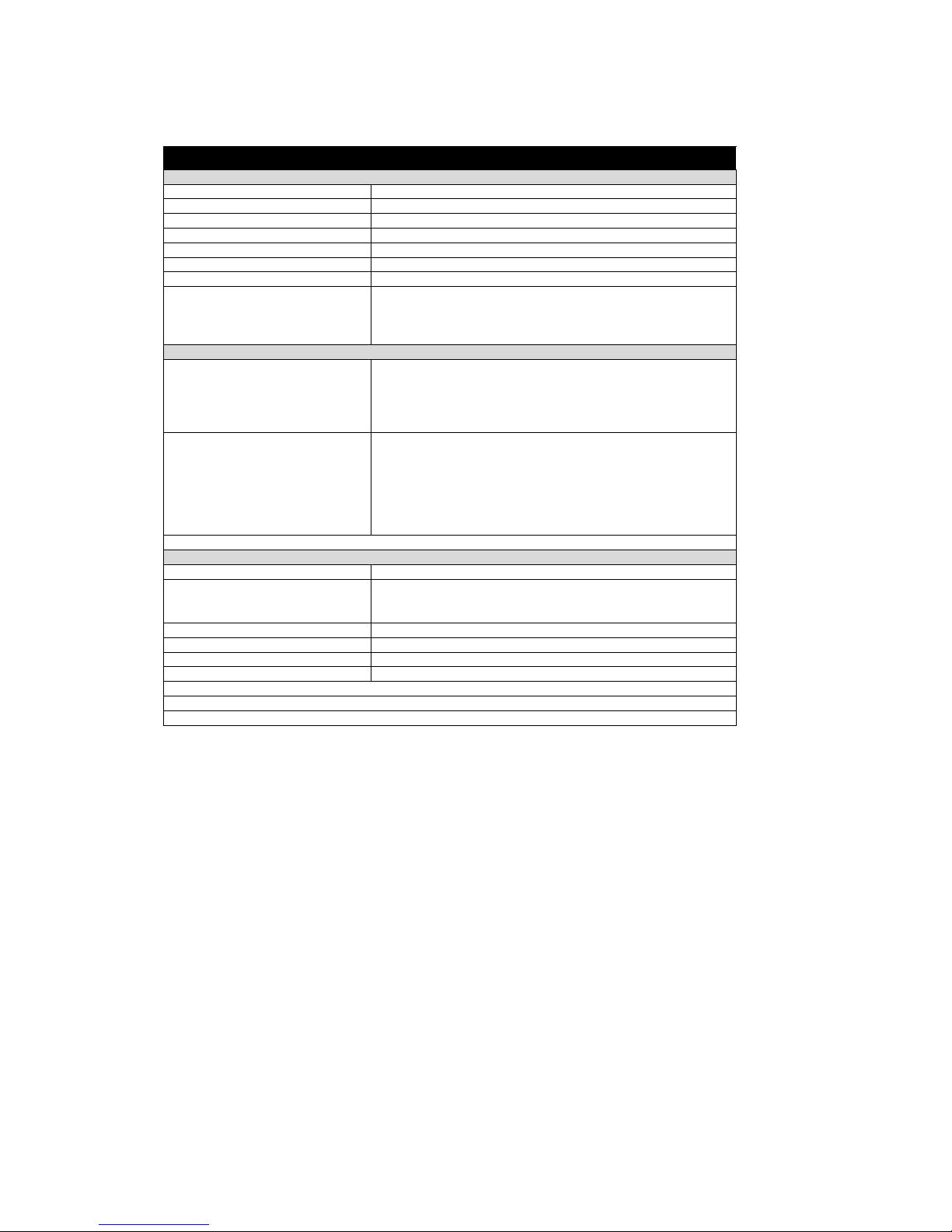
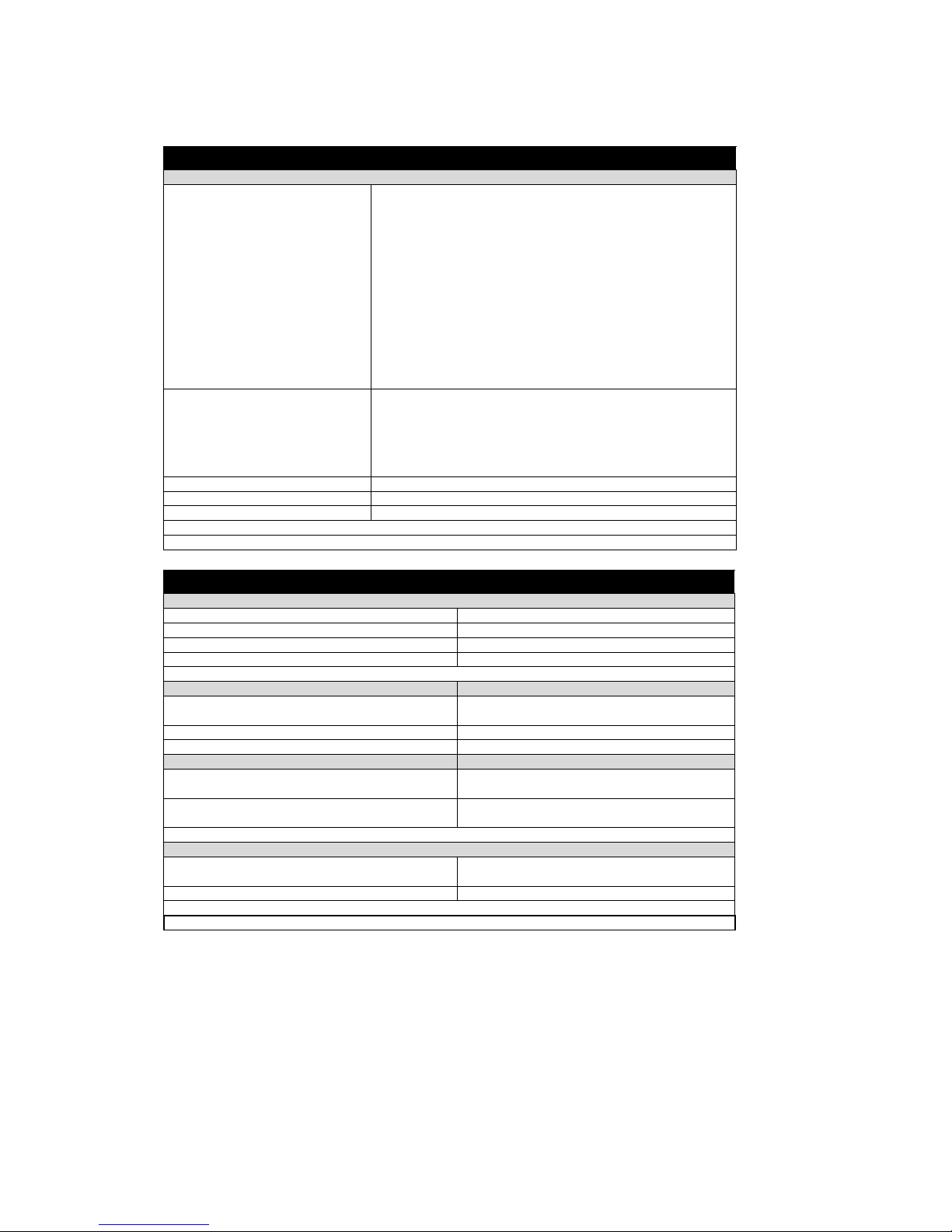
1.1 GENERAL SPECIFICATIONS (CONT’D)
Attributes
CONTROLS AND SIGNALS
On-Line LED Green
Power LED Green
Error LED Red
LED Display Panel 7-Segment Single Character
On/Off-Line Button Front Panel
Label Feed Button Front Panel
Power On/Off Button Front Panel
Self Diagnostics Head check
Paper end
Cover open
Te s t p r i n t
POTENTIOMETER ADJUSTMENTS
Adjustment Potentiometers VR1: Offset level (DIPSW6 = OFF)
VR1: Print darkness (DIPSW6 = ON)
VR2: Eye Mark
VR3: Gap sensor (to adjust the threshold)
VR4: Label pitch offset
DIP switches DIP-SW -1,2,3 : Operation mode(Print mode/Download mode)
DIP-SW -4 : Reserved (constantly OFF)
DIP-SW -5 : Head check (ON-Enabled / OFF-Disabled)
DIP-SW -6 : VR1 function switch
(ON-Print darkness level / OFF-Offset)
DIP-SW -7 : DATA dump (ON-HEX dump print / OFF-Normal print)
DIP-SW -8 : Reserved (constantly OFF)
INTERFACE CONNECTIONS
Parallel (Option) IEEE1284
Serial (Option) RS232C (up to 57.6K bps) Hardware Flow Control (Ready/Busy) Soft-
ware Flow Control (X-On/X-Off)
Bi-directional Status
USB (Option) USB Specification Version 1.1
LAN (Option) 10/100 Base-T
RFID (Option) TBA
Wireless LAN (Option) 802.11 b/g (internal)
*All specifications subject to change without notice.
Section 1: Introduction
SATO D508/D512 Operator Manual Page 1-6
1.1 GENERAL SPECIFICATIONS (CONT’D)
Barcodes
SYMBOLOGIES
Supported 1D formats
(excluding customized barcode
addressing in firmware)
UPC-A/E
EAN-8/EAN-13
CODABAR
CODE39
CODE93
CODE128
UCC/EAN128
Interleaved 2 of 5
Industrial 2 of 5
Matrix 2of5
RSS Composite
MSI
POSTNET
Bookland
Supported 2D formats PDF 417
Micro PDF 417
Truncated PDF 417
Maxicode
Data Matrix
QR Code
Ratios 1:2, 1:3, 2:5 User definable bar widths (depending on software)
Bar Height 4 to 600 dots (depending on software)
Rotation 0°, 90°, 180° and 270° (depending on software)
*All specifications subject to change without notice.
Physical Attributes
DIMENSIONS
Width 7.8 in. (198 mm)
Depth 9.1 in. (230 mm)
Height 6.6 in. (167 mm)
Weight 5.5 lbs (2.5 Kg) excluding AC adaptor
POWER REQUIREMENTS
Voltage USA: AC 115 V (+/- 10 %)
50/60 Hz (+/-1%)
Power Consumption 67W nominal
ENVIRONMENTAL
Operating 32° to 95°F (0° to 35°C),
30 to 80% RH, non-condensing
Storage 23° to 140°F (-5° to 60°C),
30-90% RH, non-condensing
REGULATORY APPROVALS
Safety USA : UL(UL60950-1)
CANADA : C-UL(CSA C22.2 No.60950-1-3)
EMC/EMS USA : FCC15B (ClassB)
Other manuals for D508
2
This manual suits for next models
1
Table of contents
Other SATO Printer manuals


SATO
SATO M-5900RVe Series User manual

SATO
SATO ARGOX OS-214EX User manual

SATO
SATO M-8490Se Series User manual

SATO
SATO MB 200i User manual

SATO
SATO M-8485Se Series User manual

SATO
SATO M8460S User manual

SATO
SATO GY412 User manual

SATO
SATO CL408e User manual

SATO
SATO SX4M User manual
 User manual")
SATO
SATO 9001226(A) User manual


