manuals.online logo
Brands
  1. Home
  2. •
  3. Brands
  4. •
  5. Sauder
  6. •
  7. Indoor Furnishing
  8. •
  9. Sauder Clifford Place 429508 User manual

Sauder Clifford Place 429508 User manual

sauder.com
NOTE: THIS INSTRUCTION
BOOKLET CONTAINS IMPORTANT
SAFETY INFORMATION.
PLEASE READ AND KEEP FOR
FUTURE REFERENCE.
sauder.com
CONTACT US FIRST
BEFORE MAKING ANY RETURNS TO THE STORE.
sauder.com
CONTACT US FIRST
BEFORE MAKING ANY RETURNS TO THE RETAILER.
Visit sauder.com/service to order replacement parts, view video assembly tips, or chat with a live rep.
Prefer the phone? Give us a ring at 1-800-445-1527.
Customer Service is available Monday-Friday - 9 a.m. to 5:30 p.m. EST (except holidays)
Sauder.com
Share your journey!
English pg 1-28
Français pg 29-32
Español pg 33-36
Lot # 557409 12/07/20
Purchased: __________________
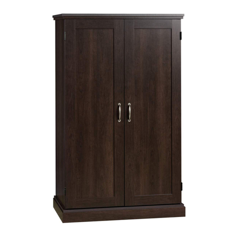
Credenza
Cliord Place Collection | Model 429508
Get all organized
and stu.
Part Identification
Hardware Identification
Assembly Steps
Français
Español
Safety
Warranty
Table of Contents Assembly Tools Required
Hammer
Not actual size
Page 2 www.sauder.com/service 429508
Use of a TV that is too heavy or large is hazardous. A TV that is too heavy will create a risk of a tip-over that can cause severe injury or
death. A TV that is too large for the available space might be accidentally pushed or bumped o the furniture, or subject to tip-over.
• Check the size and weight of your TV. Compare it to the diagram below – before you begin assembly!
• This Sauder unit is designed for use with televisions weighing less than 50 pounds. Never use with a TV that weighs more.
• The size of the television, front-to-back and side-to-side, must fit within the space defined in the diagram.
• Never place the front edge of the TV past the front edge of the TV support shelf (or stop molding – if equipped)
• Never allow the sides of the TV to extend past the side edges of the TV support surface.
• If the TV has a CRT picture tube, the picture tube cone may extend past the rear of the support shelf.
• Be sure to apply the warning label as instructed in the last assembly step. The label provides important safety related information.
WARNING
!
50 lbs.50 lbs.
18-1/2"18-1/2"
44"44"
3
3-4
5-28
29-32
33-36
37-38
39
Part Identification
åWhile not all parts are labeled, some of the parts will have a label or an inked letter on the edge
to help distinguish similar parts from each other. Use this part identification to help identify similar parts.
Now you know
our ABCs.
Page 3www.sauder.com/service429508
A RIGHT END (1)
B LEFT END (1)
C UPRIGHT (1)
D TOP (1)
E UPPER BACK (1)
F BACK (1)
G SHELF (1)
H ADJUSTABLE SHELF (1)
I LARGE BOTTOM (1)
J SMALL BOTTOM (1)
L SHORT BOTTOM MOLDING (2)
K LONG BOTTOM MOLDING (2)
M LONG TOP MOLDING (1)
N SHORT TOP MOLDING (1)
O LOWER BACK (1)
P LEFT DRAWER SIDE (1)
Q DRAWER BACK (1)
R RIGHT DRAWER SIDE (1)
S DRAWER BOTTOM (1)
T DRAWER BRACE (2)
U DRAWER FRONT (1)
V DOOR (1)
W FOOT (6)
A
B
C
D
E F
GH
IJ
K
K
L
L
MN
O
P
QR
ST
T
U
V
WWW
W
W
W
ANGLED HEAD
CAM SCREW - 30
2
Angled head
LARGE HIDDEN
CAM - 30
1
(EXTENSION SET SHOWN SEPARATED)
XEXTENSION RAIL - 2 YEXTENSION SLIDE - 2
Hardware Identification
åScrews are shown actual size. You may receive extra hardware with your unit.
Hardware Identification
Page 4 www.sauder.com/service 429508
WOOD
DOWEL - 34
6SHORT WOOD
DOWEL - 12
7
LONG WOOD
DOWEL - 4
5
METAL PIN - 4
15 RUBBER
SLEEVE - 4
16
APPLIQUE CARD - 1
13
BLACK 1-1/2" FLAT HEAD SCREW - 14
21
SILVER 1/2" FLAT HEAD SCREW - 4
24
BLACK 1/2" PAN HEAD SCREW - 18
23
SMALL HIDDEN
CAM - 8
3STRAIGHT HEAD
CAM SCREW - 8
4
Straight head
LARGE
APPLIQUE CARD - 1
14
ADJUSTABLE
GLIDE -6
10 HINGE BRACKET - 2
11 HINGE - 2
12
GROMMET - 2
9
PULL - 2
8
BLACK 1-1/8" FLAT HEAD SCREW - 12
22
17 SHORT FILE GLIDE - 2
18 LONG FILE
GLIDE - 1 19 NOTCHED FILE GLIDE - 1 20 FILE HANGER - 2
(Refer to the last step for proper
location and application)
WARNING LABEL - 1
25
522,68 22,68
50 lbs. 22 kg 22 kg
BLACK 1/2" FLAT HEAD SCREW - 4
26
Step 1 Look for this icon. It means a video assembly tip is
available at www.sauder.com/service/tips
Find the numbered video or scan the QR code.
å Assemble your unit on a carpeted floor or on the empty
carton to avoid scratching your unit or the floor.
å Push thirty HIDDEN CAMS (1) into the ENDS (A and B),
UPRIGHT (C), SHELF (G), BACKS (E, F, and O ), and
BOTTOMS (I and J).
Page 5www.sauder.com/service429508
F
C
A
B
E
O
J
I
G
Arrow
The arrow in the HIDDEN
CAM must point toward the
hole in the edge of the board.
Hole
Arrow
Arrow
(30 used)
Arrow
Arrow
1
Hole
1
1
1
Step 2
Page 6 www.sauder.com/service 429508
å Turn thirty ANGLED HEAD CAM SCREWS (2) into the
ENDS (A and B), UPRIGHT (C), and TOP (D).
å NOTE: The UPRIGHT (C) will have four ANGLED HEAD
SCREWS on one surface and six on the opposite surface.
A
B
C
C
F
L
I
P
O
V
E
R
D
Angled head
2
2
(30 used)
Remember:
Righty tighty.
Lefty loosey.
1
Step 3
Page 7www.sauder.com/service429508
å Separate the EXTENSION SLIDES (Y) from the
EXTENSION RAILS (X) as shown in the enlarged diagram
below. Be prepared, the parts are greasy.
å Fasten the EXTENSION RAILS (X) to the LEFT END (B) and
UPRIGHT (C). Use six BLACK 1/2" PAN HEAD SCREWS (23).
å NOTE: For each EXTENSION RAIL, turn a SCREW into
the hole shown in the enlarged diagram. Then, slide the
inner cartridge of the EXTENSION RAIL in to find the
other holes that lines up with the holes in the ENDS. Turn
a SCREW into those holes.
å NOTE: The EXTENSION SLIDES (Y) will be used later for
the DRAWERS.
B
C
Pull down on the black release lever and pull the SLIDE from the RAIL.
X
X
X
XY
Y
Use these holes. Open end
Open end
BLACK 1/2" PAN HEAD SCREW
(6 used in this step)
23
7
Step 4
Page 8 www.sauder.com/service 429508
F
L
I
P
O
V
E
R
F
L
I
P
O
V
E
R
I
I
J
J
å Peel an applique from the LARGE APPLIQUE CARD (14)
and stick one on each large hole in the BOTTOMS (I and J).
å Flip the BOTTOMS (I and J) over.
å Turn and tighten six FEET (W) into the threaded holes in
the BOTTOMS (I and J).
å Turn four ADJUSTABLE GLIDES (10) into the threaded
holes in the FEET (W).
14
14
W
W
W
W
W
W
10
10
Surface without
HIDDEN CAMS
Surface without
HIDDEN CAMS
Step 5
Page 9www.sauder.com/service429508
å Insert eight SHORT WOODEN DOWELS (7) into the
BOTTOMS (I and J).
å Fasten the LONG BOTTOM MOLDINGS (K) to the
LARGE BOTTOM (I). Use four BLACK 1-1/8" FLAT HEAD
SCREWS (22).
å Fasten the SHORT BOTTOM MOLDINGS (L) to the
SMALL BOTTOM (J). Use four BLACK 1-1/8" FLAT HEAD
SCREWS (22).
å NOTE: Be sure the SHORT WOODEN DOWELS insert
into the holes in the BOTTOM MOLDINGS.
7
J
I
BLACK 1-1/8" FLAT HEAD SCREW
(8 used in this step)
22
BLACK 1-1/8" FLAT HEAD SCREW
22
7
K
K
L
L
Curved edge
Step 6
Page 10 www.sauder.com/service 429508
å Insert two WOOD DOWELS (6) into the edge of the
SHELF (G).
å Fasten the SHELF (G) to the UPPER BACK (E). Use two
BLACK 1-1/2" FLAT HEAD SCREWS (21).
å NOTE: Be sure the WOOD DOWELS in the SHELF insert
into the holes in the UPPER BACK.
G
E
BLACK 1-1/2" FLAT HEAD SCREW
(2 used in this step)
21
Surface with
HIDDEN CAMS
6
Surface without
HIDDEN CAMS
Step 7
Page 11www.sauder.com/service429508
å Insert two WOOD DOWELS (6) into the edge of the
LOWER BACK (O).
å Fasten the LOWER BACK (O) to the BOTTOM (I). Use two
BLACK 1-1/2" FLAT HEAD SCREWS (21).
å NOTE: Be sure the WOOD DOWELS in the LOWER BACK
insert into the holes in the BOTTOM.
I
O
BLACK 1-1/2" FLAT HEAD SCREW
(2 used in this step)
21
6
Surface without
HIDDEN CAMS
Step 8
Page 12 www.sauder.com/service 429508
å Insert four LONG WOOD DOWELS (5) into the edge of
the LOWER BACK (O).
å Fasten the UPPER BACK (E) to the LOWER BACK (O), by
pushing it onto the WOOD DOWELS in the LOWER BACK.
å Lay your unit onto the BACKS (E and O) to prepare for the
next step.
I
O
G
E
5
5
Step 9
Page 13www.sauder.com/service429508
å Insert six WOOD DOWELS into the LEFT END (B).
å Fasten the LEFT END (B) to the SHELF (G), BACKS (E and O),
and BOTTOM (I). Tighten six HIDDEN CAMS.
å NOTE: Be sure the WOOD DOWELS in the LEFT END
insert into the holes in the SHELF, BACKS, and BOTTOM.
I
O
G
E
Just breathe.
It's going to be ok.
6
6
B
1
2
Open end of
EXTENSION
RAIL
1
Step 10
Page 14 www.sauder.com/service 429508
å Insert six WOOD DOWELS (6) into the UPRIGHT (C).
å Fasten the UPRIGHT (C) to the SHELF (G), BACKS (E and O),
and BOTTOM (I). Tighten six HIDDEN CAMS.
å NOTE: Be sure the WOOD DOWELS in the UPRIGHT
insert into the holes in the SHELF, BACKS, and BOTTOM.
6
6
I
O
G
E
C
1
Step 11
Page 15www.sauder.com/service429508
å Insert a WOOD DOWEL (6) into the hole in the edge of
the BACK (F).
å Fasten the SMALL BOTTOM (J) to the BACK (F). Use two
BLACK 1-1/2" FLAT HEAD SCREWS (21).
å NOTE: Be sure the WOOD DOWEL in the BACK inserts
into the holes in the SMALL BOTTOM.
å Lay the BACK (F) onto the floor to prepare for the next step.
6
F
J
BLACK 1-1/2" FLAT HEAD SCREW
(2 used in this step)
21
Surface without
HIDDEN CAMS
This hole must be here.
Step 12
Page 16 www.sauder.com/service 429508
å Insert four WOOD DOWELS (6) into the UPRIGHT (C).
å Fasten the BACK (F) and SMALL BOTTOM (J) to the
UPRIGHT (C). Tighten four HIDDEN CAMS.
å NOTE: Be sure the WOOD DOWELS in the UPRIGHT
insert into the BACK and SMALL BOTTOM.
Surface with
HIDDEN CAMS
J
C
F
6
1
Step 13
Page 17www.sauder.com/service429508
å Fasten the HINGE BRACKETS (11) to the RIGHT END (A)
exactly as shown in the upper diagram. Use the SCREWS
in the brackets.
å Insert four WOOD DOWELS (6) into the RIGHT END (A).
å Fasten the RIGHT END (A) to the BACK (F) and SMALL
BOTTOM (J). Tighten four HIDDEN CAMS.
å NOTE: Be sure the WOOD DOWELS in the RIGHT END
insert into the holes in the BACK and SMALL BOTTOM.
J
A
A
11
Surface with holes
F
6
1
Step 14
Page 18 www.sauder.com/service 429508
å Insert four SHORT WOODEN DOWELS (7) into the TOP (D).
å Fasten the TOP MOLDINGS (M and N) to the TOP (D).
Use four BLACK 1-1/8" FLAT HEAD SCREWS (22).
å NOTE: Be sure the SHORT WOOD DOWELS in the TOP
insert into the holes in the TOP MOLDINGS.
BLACK 1-1/8" FLAT HEAD SCREW
(4 used in this step)
22
7
7
Now might be a
good time to refresh
your drink.
Rounded edge
D
M
N
Step 15
Page 19www.sauder.com/service429508
å Carefully stand your unit upright.
å Push a GROMMET into the UPRIGHT (C) and BACK (F).
å Insert nine WOOD DOWELS (6) into the ENDS (A and B),
UPRIGHT (C), and BACKS (E and F).
å Fasten the TOP (D) to the ENDS (A and B), UPRIGHT (C),
and BACKS (E and F). Tighten ten HIDDEN CAMS.
å NOTE: Be sure the WOOD DOWELS in the ENDS,
UPRIGHT, and BACKS insert into the holes in the TOP.
D
A
B
C
E
F
9
6
6
(9 used)
Step 16
Page 20 www.sauder.com/service 429508
å Fasten the NOTCHED FILE GLIDE (19) to the DRAWER
FRONT (U). Use six BLACK 1/2" PAN HEAD SCREWS (23).
Notch
BLACK 1/2" PAN HEAD SCREW
(6 used in this step)
23
19
U

Other Sauder Indoor Furnishing manuals

Sauder Summer Home Pantry 401867 User manual

Sauder

Sauder Summer Home Pantry 401867 User manual

Sauder 427470 User manual

Sauder

Sauder 427470 User manual

Sauder 415137 User manual

Sauder

Sauder 415137 User manual

Sauder Original Cottage Collection 414684 User manual

Sauder

Sauder Original Cottage Collection 414684 User manual

Sauder 422290 User manual

Sauder

Sauder 422290 User manual

Sauder Shoal Creek Series User manual

Sauder

Sauder Shoal Creek Series User manual

Sauder Palladia 420519 User manual

Sauder

Sauder Palladia 420519 User manual

Sauder August Hill 426133 User manual

Sauder

Sauder August Hill 426133 User manual

Sauder 401294 User manual

Sauder

Sauder 401294 User manual

Sauder Embassy Point 414706 User manual

Sauder

Sauder Embassy Point 414706 User manual

Sauder Worksense BERGEN CIRCLE 426298 User manual

Sauder

Sauder Worksense BERGEN CIRCLE 426298 User manual

Sauder 414435 User manual

Sauder

Sauder 414435 User manual

Sauder Clifford Place 421113 User manual

Sauder

Sauder Clifford Place 421113 User manual

Sauder 419409 User manual

Sauder

Sauder 419409 User manual

Sauder Hammond 428247 User manual

Sauder

Sauder Hammond 428247 User manual

Sauder Edge Water Credenza 415321 User manual

Sauder

Sauder Edge Water Credenza 415321 User manual

Sauder Office Port Series User manual

Sauder

Sauder Office Port Series User manual

Sauder Office Port Library Return 408363 User manual

Sauder

Sauder Office Port Library Return 408363 User manual

Sauder Englewood 426909 User manual

Sauder

Sauder Englewood 426909 User manual

Sauder OfficeWorks AFFIRM 427439 User manual

Sauder

Sauder OfficeWorks AFFIRM 427439 User manual

Sauder Edge Water Series User manual

Sauder

Sauder Edge Water Series User manual

Sauder HomePlus 422428 User manual

Sauder

Sauder HomePlus 422428 User manual

Sauder Center City 425653 User manual

Sauder

Sauder Center City 425653 User manual

Sauder Orchard Hills 418648 User manual

Sauder

Sauder Orchard Hills 418648 User manual

Popular Indoor Furnishing manuals by other brands

ROOMS TO GO Ovis 60699 manual

ROOMS TO GO

ROOMS TO GO Ovis 60699 manual

Space Seating 829-R2C728P Assembly and operating instructions

Space Seating

Space Seating 829-R2C728P Assembly and operating instructions

Jysk KETTINGE quick start guide

Jysk

Jysk KETTINGE quick start guide

Style selections EDWARDS 36DC installation manual

Style selections

Style selections EDWARDS 36DC installation manual

Coaster 183452 Assembly instructions

Coaster

Coaster 183452 Assembly instructions

HAMPTON BAY FRS81094B-STL Use and care guide

HAMPTON BAY

HAMPTON BAY FRS81094B-STL Use and care guide

BDI Meriden 8127 Assembly instructions

BDI

BDI Meriden 8127 Assembly instructions

Exclusive Heritage BV-20060D-WMCG installation manual

Exclusive Heritage

Exclusive Heritage BV-20060D-WMCG installation manual

Walker Edison W58CSTBV2D Assembly instructions

Walker Edison

Walker Edison W58CSTBV2D Assembly instructions

Safavieh Furniture DTB1403 manual

Safavieh Furniture

Safavieh Furniture DTB1403 manual

Whalen WF36FVB manual

Whalen

Whalen WF36FVB manual

modway EEI-2266 quick start guide

modway

modway EEI-2266 quick start guide

Seconique MONACO Assembly instructions

Seconique

Seconique MONACO Assembly instructions

modway Marchesa EEI-5015 Assembly instructions

modway

modway Marchesa EEI-5015 Assembly instructions

ASH & EMBER Grade A Teak 25" Barstool user manual

ASH & EMBER

ASH & EMBER Grade A Teak 25" Barstool user manual

Muller TB 224 Assembly instruction

Muller

Muller TB 224 Assembly instruction

RTA Products TECHNI MOBILI RTA-80X5 Assembly instructions

RTA Products

RTA Products TECHNI MOBILI RTA-80X5 Assembly instructions

TOV Gala Assembly instructions

TOV

TOV Gala Assembly instructions

manuals.online logo
manuals.online logoBrands
  • About & Mission
  • Contact us
  • Privacy Policy
  • Terms and Conditions

Copyright 2025 Manuals.Online. All Rights Reserved.