manuals.online logo
Brands
  1. Home
  2. •
  3. Brands
  4. •
  5. Sauder
  6. •
  7. Indoor Furnishing
  8. •
  9. Sauder Hammond 428247 User manual

Sauder Hammond 428247 User manual

sauder.com
NOTE: THIS INSTRUCTION
BOOKLET CONTAINS IMPORTANT
SAFETY INFORMATION.
PLEASE READ AND KEEP FOR
FUTURE REFERENCE.
English pg 1-27
Français pg 28-31
Español pg 32-35
sauder.com
CONTACT US FIRST
BEFORE MAKING ANY RETURNS TO THE STORE.
sauder.com
CONTACT US FIRST
BEFORE MAKING ANY RETURNS TO THE RETAILER.
Visit sauder.com/service to order replacement parts, view video assembly tips, or chat with a live rep.
Prefer the phone? Give us a ring at 1-800-445-1527.
Customer Service is available Monday-Friday - 9 a.m. to 5:30 p.m. EST (except holidays)
Sauder.com
Share your journey! Lot # 549485 06/18/20
Purchased: __________________
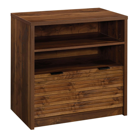
Credenza
Hammond Collection | Model 428247
For all your
newfangled gadgetry.
Part Identification
Hardware Identification
Assembly Steps
Français
Español
Safety
Warranty
No. 2 Phillips Screwdriver
Tip Shown Actual Size
Table of Contents Assembly Tools Required
2-3
4-5
6-27
28-31
32-35
36-38
39
åWhile not all parts are labeled, some of the parts will have a label or an inked letter on the edge
to help distinguish similar parts from each other. Use this part identification to help identify similar parts.
Now you know
our ABCs.
Part Identification
A TOP (1)
B LEFT END (1)
C LEFT UPRIGHT (1)
D RIGHT UPRIGHT (1)
E RIGHT END (1)
F BOTTOM (2)
G LARGE BOTTOM (1)
H LARGE BACK (2)
I BACK (2)
J PENCIL DRAWER FRONT (1)
K SHELF MOLDING (1)
L SLIDING SHELF (1)
M DOOR (2)
N ADJUSTABLE SHELF (2)
O DRAWER BRACE (1)
P DRAWER FRONT (2)
Q PENCIL DRAWER BACK (1)
R PENCIL DRAWER BOTTOM (1)
T LEFT DRAWER SIDE (2)
U RIGHT DRAWER SIDE (2)
V DRAWER BACK (2)
W DRAWER BOTTOM (2)
X PENCIL LEFT DRAWER SIDE (1)
Y PENCIL RIGHT DRAWER SIDE (1)
Z FOOT (8)
Page 2 www.sauder.com 428247
Part Identification
A
B
C
D
E
F
G
H
F
H
I
I
Y
LM
N
J
P
Q
O
R
T
UV
X
W
Z
K
M
N
P
T
U
V
W
Z
Z
Z
Z
Z
Z
Z
Page 3www.sauder.com428247
åScrews are shown actual size. You may receive extra hardware with your unit.
Hardware Identification
APPLIQUE CARD - 3
8
LARGE WOOD
DOWEL - 47
6
HIDDEN
CAM - 32
3CAM SCREW - 40
5
METAL
PIN - 8
11
KNOB SET - 6
10
SMALL HIDDEN
CAM - 8
4
SMALL WOOD
DOWEL - 8
7 9 HINGE - 4
L-WRENCH - 1
18
13 GROMMET - 4 GROMMET CAP- 2
14
(EXTENSION SET SHOWN SEPARATED)
1EXTENSION RAIL - 6 2EXTENSION SLIDE - 6
ADHESIVE TAPE - 1
17
12 LARGE GROMMET - 3
MAGNETIC CATCH - 2
15 STRIKE PLATE - 2
16
Page 4 www.sauder.com 428247
31 WIDE EXTENSION
RAIL - 2 32 WIDE EXTENSION
SLIDE - 2
(EXTENSION SET SHOWN SEPARATED)
åScrews are shown actual size. You may receive extra hardware with your unit.
Hardware Identification
BLACK 2-3/4" HEX HEAD SCREW - 16
19
BLACK 5/8" FLAT HEAD SCREW - 56
22
BLACK 1/2" FLAT HEAD SCREW - 18
24
NARROW BLACK 1/2" FLAT HEAD SCREW - 2
25
NARROW BLACK 5/8" FLAT HEAD SCREW - 4
23
BLACK 1" MACHINE SCREW - 6
21
BLACK 1-3/8" FLAT HEAD SCREW - 12
20
Page 5www.sauder.com428247
Step 1
å Assemble your unit on a carpeted floor or on the empty carton to avoid
scratching your unit or the floor.
å Turn thirty-two CAM SCREWS (5) into the exact holes shown in
the TOP (A), ENDS (B and E), both surfaces of
the UPRIGHTS (C and D), SHELF MOLDING (K),
DRAWER FRONTS (J and P), and PENCIL DRAWER BACK (Q).
å NOTE: Be sure to use the exact holes shown in the DRAWER FRONTS
and DRAWER BACK.
Page 6 www.sauder.com 428247
A
B
C
D
E
C
D
JP
P
Q
K
(32 used)
5
F
L
I
P
O
V
E
R
F
L
I
P
O
V
E
R
Meet Part (A). This component has
been engineered to be lighter, stronger,
faster… well ok. Not technically faster.
But definitely makes for a sturdier
Credenza that’s easier to assemble and
friendlier to the environment.
Look for this icon. It means a video assembly tip is
available at www.sauder.com/service/tips
Find the numbered video or scan the QR code. 1
Step
å Push thirty-two HIDDEN CAMS (3) into the ENDS (B and E),
UPRIGHTS (C and D), LARGE BOTTOM (G), LARGE BACKS (H),
and SLIDING SHELF (L).
Step 2
Page 7www.sauder.com428247
B
C
D
E
G
H
H
L
Just think. The sooner
you do this, the sooner
you do something else.
Arrow
3
Arrow
The arrow in the HIDDEN
CAM must point toward the
hole in the edge of the board.
Hole
Arrow
3
(32 used)
Part (G). Another
sturdier, easier,
friendlier component!
1
Step
å Push eight SMALL HIDDEN CAMS (4) into the
DRAWER BRACE (O) and DRAWER SIDES (T, U, X, and Y).
Step 3
Page 8 www.sauder.com 428247
O
Arrow
4
(8 used)
The arrow in the HIDDEN
CAM must point toward the
hole in the edge of the board.
Hole
Arrow
Arrow
4
Y
X
T
T
U
U
1
Step
å Insert twenty LARGE WOOD DOWELS (6) into the
exact holes shown in the ENDS (B and E), LARGE
BOTTOM (G), and LARGE BACKS (H).
Step 4
Page 9www.sauder.com428247
B
E
6
6
G
6
6
Hx 2
6
6
(20 used)
Step
Step 5
Page 10 www.sauder.com 428247
å Separate eight EXTENSION SLIDES (2) from the EXTENSION RAILS (1) as shown in the upper diagram below.
Be prepared, the parts are greasy.
å Fasten the EXTENSION RAILS (1) to the ENDS (B and E) and UPRIGHTS (C and D). Use twelve BLACK 5/8" FLAT
HEAD SCREWS (22).
å NOTE: For each EXTENSION RAIL, turn a SCREW into the 1st hole shown in the diagram. Then, slide the inner
cartridge of the EXTENSION RAIL in to find the other holes that line up with the holes in the ENDS and UPRIGHTS.
Turn a SCREW into these holes.
å NOTE: The EXTENSION SLIDES will be used later for the DRAWERS.
BLACK 5/8" FLAT HEAD SCREW
(12 used in this step)
22
B
E
C
D
1
1
1
1
Closed end
Closed end
Surface with
HIDDEN CAMS
Surface with
HIDDEN CAMS
Surface with
HIDDEN CAMS
Surface with
HIDDEN CAMS
1
2
1st hole
Closed end
Use these holes.
Open end
Push the release lever up and
pull the SLIDE from the RAIL.
Open end
1
Step
å Insert eight LARGE WOOD DOWELS (6) into the exact holes
shown in the UPRIGHTS (C and D).
å Fasten the MAGNETIC CATCH (15) to the UPRIGHTS (C and D)
exactly as shown. Use four NARROW BLACK 5/8" FLAT
HEAD SCREWS (23).
Step 6
Page 11www.sauder.com428247
C
D
6
6
NARROW BLACK 5/8" FLAT HEAD SCREW
(4 used in this step)
23
15
15
Magnet
Magnet
StepStep 7
Page 12 www.sauder.com 428247
C
D
Surface without
HIDDEN CAMS
å Separate the WIDE EXTENSION SLIDES (32) from the WIDE EXTENSION RAILS (31) as shown in the upper diagram
below. Be prepared, the parts are greasy.
å Fasten the WIDE EXTENSION RAILS (31) to the UPRIGHTS (C and D). Use eight BLACK 5/8" FLAT HEAD SCREWS (22).
å NOTE: For each WIDE EXTENSION RAIL, turn a SCREW into the hole shown in the enlarged diagram. Then, slide the
inner cartridge of the EXTENSION RAIL in to find the other holes that lines up with the holes in the UPRIGHTS. Turn a
SCREW into these holes.
å NOTE: The WIDE EXTENSION SLIDES will be used later for the SLIDING SHELF.
å Fasten two EXTENSION RAILS (1) to the UPRIGHTS (C and D). Use six BLACK 5/8" FLAT HEAD SCREWS (22).
å NOTE: For each EXTENSION RAIL, turn a SCREW into the 1st hole shown in the diagram. Then, slide the inner
cartridge of the EXTENSION RAIL in to find the other holes that lines up with the holes in the UPRIGHTS. Turn a
SCREW into these holes.
å Insert a GROMMET (13) into the large hole in the UPRIGHTS (C and D) as shown.
1
1st hole
Closed end
Use these holes.
Open end
Surface without
HIDDEN CAMS
31
1
1
BLACK 5/8" FLAT HEAD SCREW
(14 used in this step)
22
Closed end
Closed end
Open end
13
31
32
Push the release lever in and pull the SLIDE from the RAIL.
31
Closed end
13
7
StepStep 8
Page 13www.sauder.com428247
å Fasten the ENDS (B and E) and UPRIGHTS (C and D) to
the LARGE BACKS (H). Tighten eight HIDDEN CAMS.
å NOTE: Be sure to position the ENDS, UPRIGHTS, and
LARGE BACKS exactly as shown.
å NOTE: Be sure the WOOD DOWELS in the LARGE
BACKS insert into the holes in the ENDS and UPRIGHTS.
å Insert a GROMMET (13) into the large hole in the
LARGE BACKS (H) as shown.
1
2
C
D
B
E
H
H
Surface with
HIDDEN CAMS
Surface with
HIDDEN CAMS
Surface with
HIDDEN CAMS
Surface without
HIDDEN CAMS
Surface with
HIDDEN CAMS
Surface without
HIDDEN CAMS
13
13
1
Step
å Fasten the LARGE BOTTOM (G) to the UPRIGHTS (C and D).
Tighten four HIDDEN CAMS.
å Insert a LARGE GROMMET (12) into the large hole in the
LARGE BOTTOM (G).
Step 9
Page 14 www.sauder.com 428247
C
D
G
Surface with
HIDDEN CAMS
The large hole
must be here.
12
1
StepStep 10
Page 15www.sauder.com428247
å First, insert two LARGE WOOD DOWELS (6) into a FOOT (Z).
å Repeat this step for the remaining FEET (Z).
å Then, fasten the FEET (Z) to the BOTTOMS (F). Tighten sixteen
BLACK 2-3/4" HEX HEAD SCREWS (19) using the L-WRENCH (18).
å NOTE: Be sure the WOOD DOWELS in the FEET insert into the holes
in the BOTTOMS.
å Now, turn eight CAM SCREWS (5) into the exact holes shown in the
BOTTOMS (F).
(16 used)
Zx8
6
18
F
F
Z
Z
Z
Z
Z
Z
Z
Z
(8 used)
5
Part (F). Another
sturdier, easier,
friendlier component!
F
F
1st
2nd
3rd
BLACK 2-3/4" HEX HEAD SCREW
(16 used in this step)
19
1
Step
å Fasten the BOTTOMS (F) to the ENDS (B and E) and
UPRIGHTS (C and D). Tighten eight HIDDEN CAMS.
å NOTE: Be sure the WOOD DOWELS in the ENDS and
UPRIGHTS insert into the holes in the BOTTOMS.
Step 11
Page 16 www.sauder.com 428247
Side Step: Make
nachos. (Optional, but
recommended.)
F
F
C
D
E
B
Curved edge
Surface with FEET Surface with FEET
Curved edge
1
Step
å Carefully stand your unit upright.
å First, tape the seam of the BACKS (I) together using the
ADHESIVE TAPE (17).
å NOTE: The BACKS may already be taped together at
the seam.
å Next, slide the BACKS (I) into the grooves in the
UPRIGHTS (C and D).
å NOTE: The taped seam of the BACKS should face out.
Step 12
Page 17www.sauder.com428247
C
D
I
I
17
Seam
Groove
Step
å NOTE: You will need someone's help in this step.
å Carefully place the TOP (A) onto your unit and fasten it
to the ENDS (B and E) and UPRIGHTS (C and D). Tighten
eight HIDDEN CAMS.
å NOTE: Be sure the BACKS (I) insert into the groove in the
TOP (A).
å NOTE: Be sure the WOOD DOWELS in the ENDS and
UPRIGHTS insert into the holes in the TOP.
å Push a LARGE GROMMET (12) and GROMMET CAP (14)
into the large holes in the TOP (A).
Step 13
Page 18 www.sauder.com 428247
I
I
A
E
D
C
B
Groove
14
12
1
Step
å Insert three LARGE WOOD DOWELS (6) into the
SHELF MOLDING (K).
å Fasten the SHELF MOLDING (K) to the SLIDING SHELF (L).
Tighten four HIDDEN CAMS.
å Then, fasten two WIDE EXTENSION SLIDES (32) to the SLIDING
SHELF (L). Use six BLACK 5/8" FLAT HEAD SCREWS (22) into
the exact holes shown in the enlarged upper view.
Step 14
Page 19www.sauder.com428247
L
K
6
32
32
Open end
Open end
(3 used)
Surface without
HIDDEN CAMS
32 Open end
Use these holes.
BLACK 5/8" FLAT HEAD SCREW
(6 used in this step)
22
1
Step
å Fasten four EXTENSION SLIDES (2) to the
DRAWER SIDES (T, U, X, and Y). Use twelve BLACK 1/2"
FLAT HEAD SCREWS (24) into the exact holes shown in
the enlarged upper view.
å Repeat this step for the remaining DRAWER
SIDES (T and U).
Step 15
Page 20 www.sauder.com 428247
2Open end
Use these holes.
BLACK 1/2" FLAT HEAD SCREW
(18 used in this step)
24
U x 2
Tx2
2
2
Open end
Open end
2
2
Y
X
Open end
Open end
These holes
must be here.
These holes
must be here.

Other Sauder Indoor Furnishing manuals
Sauder Parklane Series User manual

Sauder

Sauder Parklane Series User manual

Sauder Cornerstone 404972 User manual

Sauder

Sauder Cornerstone 404972 User manual

Sauder Credenza 420723 User manual

Sauder

Sauder Credenza 420723 User manual

Sauder Via 419609 User manual

Sauder

Sauder Via 419609 User manual

Sauder Harvey Park Lateral File 426510 User manual

Sauder

Sauder Harvey Park Lateral File 426510 User manual

Sauder 419409 User manual

Sauder

Sauder 419409 User manual

Sauder Entertainment Credenza User manual

Sauder

Sauder Entertainment Credenza User manual

Sauder Office Port 408293 User manual

Sauder

Sauder Office Port 408293 User manual

Sauder 420566 User manual

Sauder

Sauder 420566 User manual

Sauder Parklane 423107 User manual

Sauder

Sauder Parklane 423107 User manual

Sauder Avenue Eight 416514 User manual

Sauder

Sauder Avenue Eight 416514 User manual

Sauder Orchard Hills Series User manual

Sauder

Sauder Orchard Hills Series User manual

Sauder Dakota Pass 422596 User manual

Sauder

Sauder Dakota Pass 422596 User manual

Sauder Barrister Lane 416798 User manual

Sauder

Sauder Barrister Lane 416798 User manual

Sauder Anda Norr 427707 User manual

Sauder

Sauder Anda Norr 427707 User manual

Sauder Craft Table 421417 User manual

Sauder

Sauder Craft Table 421417 User manual

Sauder Portage Park 426293 User manual

Sauder

Sauder Portage Park 426293 User manual

Sauder Lateral File Pacific View 427360 User manual

Sauder

Sauder Lateral File Pacific View 427360 User manual

Sauder Barrister Lane 414108 User manual

Sauder

Sauder Barrister Lane 414108 User manual

Sauder 422893 User manual

Sauder

Sauder 422893 User manual

Sauder August Hill 426133 User manual

Sauder

Sauder August Hill 426133 User manual

Sauder Harbor View 401685 User manual

Sauder

Sauder Harbor View 401685 User manual

Sauder Englewood 426909 User manual

Sauder

Sauder Englewood 426909 User manual

Sauder OfficeWorks AFFIRM 427444 User manual

Sauder

Sauder OfficeWorks AFFIRM 427444 User manual

Popular Indoor Furnishing manuals by other brands

Garden Treasures MW-2387-AC-F manual

Garden Treasures

Garden Treasures MW-2387-AC-F manual

Next LEAMINGTON NICKEL 988724 Assembly instructions

Next

Next LEAMINGTON NICKEL 988724 Assembly instructions

fantastic furniture COMO ROBE 2 DOOR manual

fantastic furniture

fantastic furniture COMO ROBE 2 DOOR manual

siena GARDEN Alexis C30939 Assembly instruction

siena GARDEN

siena GARDEN Alexis C30939 Assembly instruction

George & Willy Wooden Block Letter Board instructions

George & Willy

George & Willy Wooden Block Letter Board instructions

Walker Edison W52C4D0 Assembly instructions

Walker Edison

Walker Edison W52C4D0 Assembly instructions

Habitat Allegro quick start guide

Habitat

Habitat Allegro quick start guide

Next NEW MADSEN OPEN TV 446167 Assembly instructions

Next

Next NEW MADSEN OPEN TV 446167 Assembly instructions

Rauch M1829 Assembly instructions

Rauch

Rauch M1829 Assembly instructions

Vivo CHAIR-S04F instruction manual

Vivo

Vivo CHAIR-S04F instruction manual

Screen Innovations Nano Roll 375 Series installation instructions

Screen Innovations

Screen Innovations Nano Roll 375 Series installation instructions

LIVIQUE Hedy 6716237 Assembly instructions

LIVIQUE

LIVIQUE Hedy 6716237 Assembly instructions

composad FSC Galaverna PN4012K56104 manual

composad

composad FSC Galaverna PN4012K56104 manual

kd frames CHARLESTON 3991-CP-Q instructions

kd frames

kd frames CHARLESTON 3991-CP-Q instructions

Ercol Ancona 5152 quick start guide

Ercol

Ercol Ancona 5152 quick start guide

Next A34785 Assembly instructions

Next

Next A34785 Assembly instructions

Vivo DESK-TOP1B instruction manual

Vivo

Vivo DESK-TOP1B instruction manual

avaks nabytok REA AMY 16 Assembly instructions

avaks nabytok

avaks nabytok REA AMY 16 Assembly instructions

manuals.online logo
manuals.online logoBrands
  • About & Mission
  • Contact us
  • Privacy Policy
  • Terms and Conditions

Copyright 2025 Manuals.Online. All Rights Reserved.