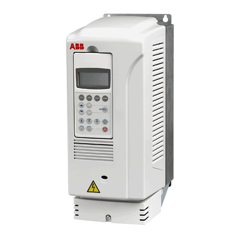
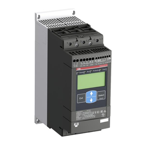
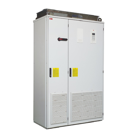
ABB BALDOR ACB530 User manual

12/12 Installation & Operating Manual MN796-ACB530
User’s manual
ACB530

Any trademarks used in this manual are the property of their respective owners.
Important:
Be sure to check www.baldor.com for the latest software, rmware and drivers for your VS1GV product. Also you can
download the latest version of this manual in Adobe Acrobat PDF format.

iMN796 - ACB530
Chapter 1
Introduction
1.1 Manual Introduction . . . . . . . . . . . . . . . . . . . . . . . . . . . . . . . . . . . . . . . . . . . . . . . . . . . . . . . . . . . . . . 1-1
1.1.1 What This Chapter Contains . . . . . . . . . . . . . . . . . . . . . . . . . . . . . . . . . . . . . . . . . . . . . . . . . . . 1-1
1.1.2 Applicable Firmware Versions . . . . . . . . . . . . . . . . . . . . . . . . . . . . . . . . . . . . . . . . . . . . . . . . . . 1-1
1.1.3 Purpose of the Manual. . . . . . . . . . . . . . . . . . . . . . . . . . . . . . . . . . . . . . . . . . . . . . . . . . . . . . . . 1-1
1.1.2 Related Documents . . . . . . . . . . . . . . . . . . . . . . . . . . . . . . . . . . . . . . . . . . . . . . . . . . . . . . . . . . 1-1
1.1.3 Categorization by Frame Size . . . . . . . . . . . . . . . . . . . . . . . . . . . . . . . . . . . . . . . . . . . . . . . . . . 1-1
1.2 Safety Notices . . . . . . . . . . . . . . . . . . . . . . . . . . . . . . . . . . . . . . . . . . . . . . . . . . . . . . . . . . . . . . . . . . . 1-1
1.3 Use of Warnings. . . . . . . . . . . . . . . . . . . . . . . . . . . . . . . . . . . . . . . . . . . . . . . . . . . . . . . . . . . . . . . . . . 1-1
1.4 Safety Related to Installation and Maintenance . . . . . . . . . . . . . . . . . . . . . . . . . . . . . . . . . . . . . . . . . 1-1
1.4.1 Electrical Safety . . . . . . . . . . . . . . . . . . . . . . . . . . . . . . . . . . . . . . . . . . . . . . . . . . . . . . . . . . . . 1-1
1.4.2 General Safety . . . . . . . . . . . . . . . . . . . . . . . . . . . . . . . . . . . . . . . . . . . . . . . . . . . . . . . . . . . . . 1-2
1.5 Unpacking . . . . . . . . . . . . . . . . . . . . . . . . . . . . . . . . . . . . . . . . . . . . . . . . . . . . . . . . . . . . . . . . . . . . . . 1-2
1.6 Inspection . . . . . . . . . . . . . . . . . . . . . . . . . . . . . . . . . . . . . . . . . . . . . . . . . . . . . . . . . . . . . . . . . . . . . . 1-3
1.7 Type Designation Label . . . . . . . . . . . . . . . . . . . . . . . . . . . . . . . . . . . . . . . . . . . . . . . . . . . . . . . . . . . . 1-3
1.7.1 Serial Number Explanation . . . . . . . . . . . . . . . . . . . . . . . . . . . . . . . . . . . . . . . . . . . . . . . . . . . . 1-3
1.8 Safe Start-Up and Operation . . . . . . . . . . . . . . . . . . . . . . . . . . . . . . . . . . . . . . . . . . . . . . . . . . . . . . . . 1-3
1.8.1 Electrical Safety . . . . . . . . . . . . . . . . . . . . . . . . . . . . . . . . . . . . . . . . . . . . . . . . . . . . . . . . . . . . . 1-3
1.8.2 General Safety . . . . . . . . . . . . . . . . . . . . . . . . . . . . . . . . . . . . . . . . . . . . . . . . . . . . . . . . . . . . . . 1-4
1.9 Terms and Abbreviations . . . . . . . . . . . . . . . . . . . . . . . . . . . . . . . . . . . . . . . . . . . . . . . . . . . . . . . . . . . 1-4
1.10 Operation Principle and Hardware Description . . . . . . . . . . . . . . . . . . . . . . . . . . . . . . . . . . . . . . . . . 1-6
Chapter 2
General Information and Ratings
2.1 Type Designation . . . . . . . . . . . . . . . . . . . . . . . . . . . . . . . . . . . . . . . . . . . . . . . . . . . . . . . . . . . . . . . . . 2-1
2.1.1 Serial Number . . . . . . . . . . . . . . . . . . . . . . . . . . . . . . . . . . . . . . . . . . . . . . . . . . . . . . . . . . . . . . 2-2
2.1.2 Ratings and Frame Size. . . . . . . . . . . . . . . . . . . . . . . . . . . . . . . . . . . . . . . . . . . . . . . . . . . . . . . 2-2
2.2 Degrees of Protection . . . . . . . . . . . . . . . . . . . . . . . . . . . . . . . . . . . . . . . . . . . . . . . . . . . . . . . . . . . . . 2-5
Chapter 3
Installing the Drive
3.1 Mechanical Installation . . . . . . . . . . . . . . . . . . . . . . . . . . . . . . . . . . . . . . . . . . . . . . . . . . . . . . . . . . . . 3-1
3.1.1 What This Chapter Contains. . . . . . . . . . . . . . . . . . . . . . . . . . . . . . . . . . . . . . . . . . . . . . . . . . . 3-1
3.1.2 Checking the Installation Site . . . . . . . . . . . . . . . . . . . . . . . . . . . . . . . . . . . . . . . . . . . . . . . . . . 3-1
3.1.3 Requirements for the Installation Site. . . . . . . . . . . . . . . . . . . . . . . . . . . . . . . . . . . . . . . . . . . . 3-1
3.1.4 Location Instructions . . . . . . . . . . . . . . . . . . . . . . . . . . . . . . . . . . . . . . . . . . . . . . . . . . . . . . . . 3-1
3.1.5 Conrm That the Enclosure is Appropriate Based on the Site Contamination Level . . . . . . . . 3-1
3.1.6 Conrm That the Mounting Location Meets the Following Guidelines. . . . . . . . . . . . . . . . . . . 3-2
3.2 Tools Required . . . . . . . . . . . . . . . . . . . . . . . . . . . . . . . . . . . . . . . . . . . . . . . . . . . . . . . . . . . . . . . . . . . 3-2
3.3 Watts-Loss Data . . . . . . . . . . . . . . . . . . . . . . . . . . . . . . . . . . . . . . . . . . . . . . . . . . . . . . . . . . . . . . . . . 3-2
3.4 Dimensions and Weights . . . . . . . . . . . . . . . . . . . . . . . . . . . . . . . . . . . . . . . . . . . . . . . . . . . . . . . . . . . 3-3
3.4.1 Dimensions and Weights . . . . . . . . . . . . . . . . . . . . . . . . . . . . . . . . . . . . . . . . . . . . . . . . . . . . . 3-3
3.4.2 Weight . . . . . . . . . . . . . . . . . . . . . . . . . . . . . . . . . . . . . . . . . . . . . . . . . . . . . . . . . . . . . . . . . . . . 3-5
3.5 Prepare to Mount the Drive. . . . . . . . . . . . . . . . . . . . . . . . . . . . . . . . . . . . . . . . . . . . . . . . . . . . . . . . . . 3-6
3.5.1 Remove the Front Cover. . . . . . . . . . . . . . . . . . . . . . . . . . . . . . . . . . . . . . . . . . . . . . . . . . . . . . 3-6
3.6 Mount the Drive . . . . . . . . . . . . . . . . . . . . . . . . . . . . . . . . . . . . . . . . . . . . . . . . . . . . . . . . . . . . . . . . . . 3-8
3.6.1 IP21 / UL type 1 . . . . . . . . . . . . . . . . . . . . . . . . . . . . . . . . . . . . . . . . . . . . . . . . . . . . . . . . . . . . 3-8
3.6.2 IP54 / UP type 12 . . . . . . . . . . . . . . . . . . . . . . . . . . . . . . . . . . . . . . . . . . . . . . . . . . . . . . . . . . . 3-8
Table of Contents

ii MN796 - ACB530
Chapter 4
Power Wiring
4.1 Electrical Installation . . . . . . . . . . . . . . . . . . . . . . . . . . . . . . . . . . . . . . . . . . . . . . . . . . . . . . . . . . . . . . 4-1
4.1.1 What this Chapter Contains. . . . . . . . . . . . . . . . . . . . . . . . . . . . . . . . . . . . . . . . . . . . . . . . . . . . 4-1
4.2 Checking the Insulation of the Assembly. . . . . . . . . . . . . . . . . . . . . . . . . . . . . . . . . . . . . . . . . . . . . . . 4-1
4.2.1 Drive. . . . . . . . . . . . . . . . . . . . . . . . . . . . . . . . . . . . . . . . . . . . . . . . . . . . . . . . . . . . . . . . . . . . . . 4-1
4.3 Planning the Electrical Installation . . . . . . . . . . . . . . . . . . . . . . . . . . . . . . . . . . . . . . . . . . . . . . . . . . . . 4-1
4.3.1 What this Section Contains . . . . . . . . . . . . . . . . . . . . . . . . . . . . . . . . . . . . . . . . . . . . . . . . . . . . 4-1
4.3.2 Implementing the AC Power Line Connection. . . . . . . . . . . . . . . . . . . . . . . . . . . . . . . . . . . . . . 4-1
4.3.3 Disconnecting Device for Isolation . . . . . . . . . . . . . . . . . . . . . . . . . . . . . . . . . . . . . . . . . . . . . . . 4-1
4.4 Grounding the Drive. . . . . . . . . . . . . . . . . . . . . . . . . . . . . . . . . . . . . . . . . . . . . . . . . . . . . . . . . . . . . . . 4-2
4.4.1 Ground Connections . . . . . . . . . . . . . . . . . . . . . . . . . . . . . . . . . . . . . . . . . . . . . . . . . . . . . . . . . 4-2
4.4.2 Ground Fault Protection. . . . . . . . . . . . . . . . . . . . . . . . . . . . . . . . . . . . . . . . . . . . . . . . . . . . . . . 4-2
4.4.3 Grounding and Routing. . . . . . . . . . . . . . . . . . . . . . . . . . . . . . . . . . . . . . . . . . . . . . . . . . . . . . . . 4-2
4.5 Wiring Overview . . . . . . . . . . . . . . . . . . . . . . . . . . . . . . . . . . . . . . . . . . . . . . . . . . . . . . . . . . . . . . . . . . 4-3
4.5.1 Conduit/Gland Kit . . . . . . . . . . . . . . . . . . . . . . . . . . . . . . . . . . . . . . . . . . . . . . . . . . . . . . . . . . . . 4-3
4.5.2 Wiring Requirements. . . . . . . . . . . . . . . . . . . . . . . . . . . . . . . . . . . . . . . . . . . . . . . . . . . . . . . . . . 4-4
4.5.3 Install the Wiring . . . . . . . . . . . . . . . . . . . . . . . . . . . . . . . . . . . . . . . . . . . . . . . . . . . . . . . . . . . . . 4-4
4.5.4 Wiring IP21 / UL Type 1 Enclosure with Cables . . . . . . . . . . . . . . . . . . . . . . . . . . . . . . . . . . . . . 4-4
4.5.5 Wiring IP21 / UL Type 1 Enclosure with Conduit . . . . . . . . . . . . . . . . . . . . . . . . . . . . . . . . . . . . 4-6
4.5.6 Wiring IP54 / UL Type 12 Enclosure with Cables . . . . . . . . . . . . . . . . . . . . . . . . . . . . . . . . . . . . 4-7
4.5.7 Wiring IP54 / UL Type 12 Enclosure with Conduit . . . . . . . . . . . . . . . . . . . . . . . . . . . . . . . . . . . 4-8
4.5.8 Power Connection Diagrams . . . . . . . . . . . . . . . . . . . . . . . . . . . . . . . . . . . . . . . . . . . . . . . . . . . 4-9
4.5.9 Disconnecting the Internal EMC Filter . . . . . . . . . . . . . . . . . . . . . . . . . . . . . . . . . . . . . . . . . . . . 4-10
4.6 Drive’s Power Connection Terminals . . . . . . . . . . . . . . . . . . . . . . . . . . . . . . . . . . . . . . . . . . . . . . . . . . 4-11
4.6.1 Power Terminal Considerations - R6 Frame Size . . . . . . . . . . . . . . . . . . . . . . . . . . . . . . . . . . . . 4-11
4.6.2 Crimp-On Ring Lugs . . . . . . . . . . . . . . . . . . . . . . . . . . . . . . . . . . . . . . . . . . . . . . . . . . . . . . . . . . 4-11
4.6.3 Screw-On Terminal Lugs. . . . . . . . . . . . . . . . . . . . . . . . . . . . . . . . . . . . . . . . . . . . . . . . . . . . . . . 4-12
4.7 Input Power Connections . . . . . . . . . . . . . . . . . . . . . . . . . . . . . . . . . . . . . . . . . . . . . . . . . . . . . . . . . . 4-13
4.7.1 Input Power Specications . . . . . . . . . . . . . . . . . . . . . . . . . . . . . . . . . . . . . . . . . . . . . . . . . . . . . 4-13
4.7.2 Input Power Cables/Wiring . . . . . . . . . . . . . . . . . . . . . . . . . . . . . . . . . . . . . . . . . . . . . . . . . . . . . 4-13
4.8 Brake Components. . . . . . . . . . . . . . . . . . . . . . . . . . . . . . . . . . . . . . . . . . . . . . . . . . . . . . . . . . . . . . . . 4-14
4.8.1 Compatibility. . . . . . . . . . . . . . . . . . . . . . . . . . . . . . . . . . . . . . . . . . . . . . . . . . . . . . . . . . . . . . . . 4-14
4.8.2 Selecting the Braking Resistors (Frame Sizes R1 and R2) . . . . . . . . . . . . . . . . . . . . . . . . . . . . . 4-14
4.8.3 Symbols . . . . . . . . . . . . . . . . . . . . . . . . . . . . . . . . . . . . . . . . . . . . . . . . . . . . . . . . . . . . . . . . . . . 4-16
4.8.4 Installing and Wiring Resistors . . . . . . . . . . . . . . . . . . . . . . . . . . . . . . . . . . . . . . . . . . . . . . . . . . 4-16
4.8.5 Mandatory Circuit Protection . . . . . . . . . . . . . . . . . . . . . . . . . . . . . . . . . . . . . . . . . . . . . . . . . . . 4-16
4.8.6 Parameter Set-Up. . . . . . . . . . . . . . . . . . . . . . . . . . . . . . . . . . . . . . . . . . . . . . . . . . . . . . . . . . . . 4-16
4.9 Motor Connections . . . . . . . . . . . . . . . . . . . . . . . . . . . . . . . . . . . . . . . . . . . . . . . . . . . . . . . . . . . . . . . . 4-16
4.9.1 Motor Connection Specications . . . . . . . . . . . . . . . . . . . . . . . . . . . . . . . . . . . . . . . . . . . . . . . . 4-17
4.9.2 Motor Cable Lengths . . . . . . . . . . . . . . . . . . . . . . . . . . . . . . . . . . . . . . . . . . . . . . . . . . . . . . . . . 4-17
4.9.3 Motor Thermal Protection. . . . . . . . . . . . . . . . . . . . . . . . . . . . . . . . . . . . . . . . . . . . . . . . . . . . . . 4-18
4.9.4 Emergency Stop Devices . . . . . . . . . . . . . . . . . . . . . . . . . . . . . . . . . . . . . . . . . . . . . . . . . . . . . . 4-18
4.10 Fuses. . . . . . . . . . . . . . . . . . . . . . . . . . . . . . . . . . . . . . . . . . . . . . . . . . . . . . . . . . . . . . . . . . . . . . . . . . 4-19
4.11 Check Installation . . . . . . . . . . . . . . . . . . . . . . . . . . . . . . . . . . . . . . . . . . . . . . . . . . . . . . . . . . . . . . . . 4-20

iiiMN796 - ACB530
Chapter 5
Control Wiring
5.1 Control Connection Specications . . . . . . . . . . . . . . . . . . . . . . . . . . . . . . . . . . . . . . . . . . . . . . . . . . . 5-1
5.1.1 What this chapter contains . . . . . . . . . . . . . . . . . . . . . . . . . . . . . . . . . . . . . . . . . . . . . . . . . . . . 5-1
5.2 Selecting the Control Cables . . . . . . . . . . . . . . . . . . . . . . . . . . . . . . . . . . . . . . . . . . . . . . . . . . . . . . . . 5-1
5.2.1 General Rules. . . . . . . . . . . . . . . . . . . . . . . . . . . . . . . . . . . . . . . . . . . . . . . . . . . . . . . . . . . . . . . 5-1
5.2.2 Drive’s Control Connection Terminals . . . . . . . . . . . . . . . . . . . . . . . . . . . . . . . . . . . . . . . . . . . . 5-2
5.2.3 Control Terminals Table. . . . . . . . . . . . . . . . . . . . . . . . . . . . . . . . . . . . . . . . . . . . . . . . . . . . . . . . 5.2
5.3 Reinstall the Cover . . . . . . . . . . . . . . . . . . . . . . . . . . . . . . . . . . . . . . . . . . . . . . . . . . . . . . . . . . . . . . . . 5-3
5.3.2 IP54 / UL Type 12 . . . . . . . . . . . . . . . . . . . . . . . . . . . . . . . . . . . . . . . . . . . . . . . . . . . . . . . . . . . . 5-4
5.4 Application Operating Modes . . . . . . . . . . . . . . . . . . . . . . . . . . . . . . . . . . . . . . . . . . . . . . . . . . . . . . . . 5-4
5.4.1 ABB 2-Wire Operating Mode . . . . . . . . . . . . . . . . . . . . . . . . . . . . . . . . . . . . . . . . . . . . . . . . . . . 5-5
5.4.2 ABB 3-Wire Operating Mode . . . . . . . . . . . . . . . . . . . . . . . . . . . . . . . . . . . . . . . . . . . . . . . . . . . 5-6
5.4.3 Baldor 2-Wire Operating Mode. . . . . . . . . . . . . . . . . . . . . . . . . . . . . . . . . . . . . . . . . . . . . . . . . . 5-7
5.4.4 Motor Potentiometer Operating Mode . . . . . . . . . . . . . . . . . . . . . . . . . . . . . . . . . . . . . . . . . . . . 5-8
5.4.5 Hand-Auto Operating Mode . . . . . . . . . . . . . . . . . . . . . . . . . . . . . . . . . . . . . . . . . . . . . . . . . . . . 5-9
5.4.6 PID Control Operating Mode . . . . . . . . . . . . . . . . . . . . . . . . . . . . . . . . . . . . . . . . . . . . . . . . . . . 5-10
5.6 Operating Mode Default Values for Parameters . . . . . . . . . . . . . . . . . . . . . . . . . . . . . . . . . . . . . . . . . 5-12
Chapter 6
Using the Keypad
6.1 Keypads. . . . . . . . . . . . . . . . . . . . . . . . . . . . . . . . . . . . . . . . . . . . . . . . . . . . . . . . . . . . . . . . . . . . . . . . 6-1
6.1.1 About Keypads . . . . . . . . . . . . . . . . . . . . . . . . . . . . . . . . . . . . . . . . . . . . . . . . . . . . . . . . . . . . . 6-1
6.2 Assistant Keypad . . . . . . . . . . . . . . . . . . . . . . . . . . . . . . . . . . . . . . . . . . . . . . . . . . . . . . . . . . . . . . . . . 6-1
6.2.1 About Keypads . . . . . . . . . . . . . . . . . . . . . . . . . . . . . . . . . . . . . . . . . . . . . . . . . . . . . . . . . . . . . 6-1
6.2.2 Overview . . . . . . . . . . . . . . . . . . . . . . . . . . . . . . . . . . . . . . . . . . . . . . . . . . . . . . . . . . . . . . . . . . . 6-2
6.2.3 Status Line . . . . . . . . . . . . . . . . . . . . . . . . . . . . . . . . . . . . . . . . . . . . . . . . . . . . . . . . . . . . . . . . . 6-3
6.2.4 Operation . . . . . . . . . . . . . . . . . . . . . . . . . . . . . . . . . . . . . . . . . . . . . . . . . . . . . . . . . . . . . . . . . . 6-3
6.2.5 Output Mode. . . . . . . . . . . . . . . . . . . . . . . . . . . . . . . . . . . . . . . . . . . . . . . . . . . . . . . . . . . . . . . . 6-5
6.2.6 Parameter Mode . . . . . . . . . . . . . . . . . . . . . . . . . . . . . . . . . . . . . . . . . . . . . . . . . . . . . . . . . . . . . 6-7
6.2.7 Assistants Mode . . . . . . . . . . . . . . . . . . . . . . . . . . . . . . . . . . . . . . . . . . . . . . . . . . . . . . . . . . . . . 6-9
6.2.8 Changed Parameters Mode . . . . . . . . . . . . . . . . . . . . . . . . . . . . . . . . . . . . . . . . . . . . . . . . . . . . 6-11
6.2.9 Fault Logger Mode . . . . . . . . . . . . . . . . . . . . . . . . . . . . . . . . . . . . . . . . . . . . . . . . . . . . . . . . . . . 6-12
6.2.10 Time and Date Mode . . . . . . . . . . . . . . . . . . . . . . . . . . . . . . . . . . . . . . . . . . . . . . . . . . . . . . . . 6-12
6.2.11 Parameter Backup Mode . . . . . . . . . . . . . . . . . . . . . . . . . . . . . . . . . . . . . . . . . . . . . . . . . . . . . 6-14
6.2.12 I/O Settings Mode. . . . . . . . . . . . . . . . . . . . . . . . . . . . . . . . . . . . . . . . . . . . . . . . . . . . . . . . . . . 6-17
Chapter 7
Parameter Descriptions
7.1 Parameters. . . . . . . . . . . . . . . . . . . . . . . . . . . . . . . . . . . . . . . . . . . . . . . . . . . . . . . . . . . . . . . . . . . . . . 7-1

iv MN796 - ACB530
Chapter 8
Start-Up, Motor Model Calc & Customizing Your Application
8.1 Starting Up the Drive . . . . . . . . . . . . . . . . . . . . . . . . . . . . . . . . . . . . . . . . . . . . . . . . . . . . . . . . . . . . . . 8-1
8.1.1 Starting up the Drive without a Keypad . . . . . . . . . . . . . . . . . . . . . . . . . . . . . . . . . . . . . . . . . . . 8-1
8.1.2 Performing a Manual Start-up . . . . . . . . . . . . . . . . . . . . . . . . . . . . . . . . . . . . . . . . . . . . . . . . . . 8-1
8.1.3 Performing a Guided Start-Up . . . . . . . . . . . . . . . . . . . . . . . . . . . . . . . . . . . . . . . . . . . . . . . . . . 8-5
8.2 Controlling the Drive through the I/O Interface. . . . . . . . . . . . . . . . . . . . . . . . . . . . . . . . . . . . . . . . . . . 8-6
8.2.1 Preliminary Settings . . . . . . . . . . . . . . . . . . . . . . . . . . . . . . . . . . . . . . . . . . . . . . . . . . . . . . . . . . 8-6
8.2.2 Starting and Controlling the Speed of the Motor . . . . . . . . . . . . . . . . . . . . . . . . . . . . . . . . . . . . 8-7
8.2.3 Changing the Direction of the Motor Rotation . . . . . . . . . . . . . . . . . . . . . . . . . . . . . . . . . . . . . . 8-7
8.2.4 Stopping the Motor. . . . . . . . . . . . . . . . . . . . . . . . . . . . . . . . . . . . . . . . . . . . . . . . . . . . . . . . . . . 8-7
8.3 Performing Motor Model Calc. . . . . . . . . . . . . . . . . . . . . . . . . . . . . . . . . . . . . . . . . . . . . . . . . . . . . . . . 8-7
8.3.1 Motor Model Calc . . . . . . . . . . . . . . . . . . . . . . . . . . . . . . . . . . . . . . . . . . . . . . . . . . . . . . . . . . . . 8-8
8.4 Program features
8.4.1 Start-up assistant . . . . . . . . . . . . . . . . . . . . . . . . . . . . . . . . . . . . . . . . . . . . . . . . . . . . . . . . . . . . 8-8
8.5 Local control vs. external control . . . . . . . . . . . . . . . . . . . . . . . . . . . . . . . . . . . . . . . . . . . . . . . . . . . . . 8-10
8.5.1 Local control . . . . . . . . . . . . . . . . . . . . . . . . . . . . . . . . . . . . . . . . . . . . . . . . . . . . . . . . . . . . . . . . 8-11
8.5.2 External control. . . . . . . . . . . . . . . . . . . . . . . . . . . . . . . . . . . . . . . . . . . . . . . . . . . . . . . . . . . . . . 8-11
8.5.3 Settings. . . . . . . . . . . . . . . . . . . . . . . . . . . . . . . . . . . . . . . . . . . . . . . . . . . . . . . . . . . . . . . . . . . . 8-11
8.5.4 Diagnostics . . . . . . . . . . . . . . . . . . . . . . . . . . . . . . . . . . . . . . . . . . . . . . . . . . . . . . . . . . . . . . . . . 8-11
8.5.6 Block diagram: Reference source for EXT1 . . . . . . . . . . . . . . . . . . . . . . . . . . . . . . . . . . . . . . . . 8-12
8.6 Reference types and processing . . . . . . . . . . . . . . . . . . . . . . . . . . . . . . . . . . . . . . . . . . . . . . . . . . . . . 8-12
8.6.1 Settings. . . . . . . . . . . . . . . . . . . . . . . . . . . . . . . . . . . . . . . . . . . . . . . . . . . . . . . . . . . . . . . . . . . . 8-13
8.7 Programmable analog inputs . . . . . . . . . . . . . . . . . . . . . . . . . . . . . . . . . . . . . . . . . . . . . . . . . . . . . . . . 8-13
8.7.1 Settings. . . . . . . . . . . . . . . . . . . . . . . . . . . . . . . . . . . . . . . . . . . . . . . . . . . . . . . . . . . . . . . . . . . . 8-13
8.7.2 Diagnostics . . . . . . . . . . . . . . . . . . . . . . . . . . . . . . . . . . . . . . . . . . . . . . . . . . . . . . . . . . . . . . . . . 8-13
8.8 Programmable analog output . . . . . . . . . . . . . . . . . . . . . . . . . . . . . . . . . . . . . . . . . . . . . . . . . . . . . . . . 8-13
8.8.1 Settings. . . . . . . . . . . . . . . . . . . . . . . . . . . . . . . . . . . . . . . . . . . . . . . . . . . . . . . . . . . . . . . . . . . . 8-14
8.8.2 Diagnostics . . . . . . . . . . . . . . . . . . . . . . . . . . . . . . . . . . . . . . . . . . . . . . . . . . . . . . . . . . . . . . . . . 8-14
8.9 Programmable digital inputs. . . . . . . . . . . . . . . . . . . . . . . . . . . . . . . . . . . . . . . . . . . . . . . . . . . . . . . . . 8-14
8.9.1 Settings. . . . . . . . . . . . . . . . . . . . . . . . . . . . . . . . . . . . . . . . . . . . . . . . . . . . . . . . . . . . . . . . . . . . 8-14
8.10 Programmable relay output . . . . . . . . . . . . . . . . . . . . . . . . . . . . . . . . . . . . . . . . . . . . . . . . . . . . . . . . 8-14
8.10.1 Settings. . . . . . . . . . . . . . . . . . . . . . . . . . . . . . . . . . . . . . . . . . . . . . . . . . . . . . . . . . . . . . . . . . . 8-14
8.10.2 Diagnostics . . . . . . . . . . . . . . . . . . . . . . . . . . . . . . . . . . . . . . . . . . . . . . . . . . . . . . . . . . . . . . . . 8-14
8.11 Actual signals . . . . . . . . . . . . . . . . . . . . . . . . . . . . . . . . . . . . . . . . . . . . . . . . . . . . . . . . . . . . . . . . . . . 8-15
8.11.1 Settings. . . . . . . . . . . . . . . . . . . . . . . . . . . . . . . . . . . . . . . . . . . . . . . . . . . . . . . . . . . . . . . . . . . 8-15
8.11.2 Diagnostics . . . . . . . . . . . . . . . . . . . . . . . . . . . . . . . . . . . . . . . . . . . . . . . . . . . . . . . . . . . . . . . . 8-15
8.12 Motor identication . . . . . . . . . . . . . . . . . . . . . . . . . . . . . . . . . . . . . . . . . . . . . . . . . . . . . . . . . . . . . . . 8-15
8.12.1 Settings. . . . . . . . . . . . . . . . . . . . . . . . . . . . . . . . . . . . . . . . . . . . . . . . . . . . . . . . . . . . . . . . . . . 8-15
8.13 Power loss ride-through. . . . . . . . . . . . . . . . . . . . . . . . . . . . . . . . . . . . . . . . . . . . . . . . . . . . . . . . 8-15
8.13 Power loss ride-through . . . . . . . . . . . . . . . . . . . . . . . . . . . . . . . . . . . . . . . . . . . . . . . . . . . . . . . . . . . 8-15
8.13.1 Settings. . . . . . . . . . . . . . . . . . . . . . . . . . . . . . . . . . . . . . . . . . . . . . . . . . . . . . . . . . . . . . . . . . . 8-16
8.14 DC magnetizing. . . . . . . . . . . . . . . . . . . . . . . . . . . . . . . . . . . . . . . . . . . . . . . . . . . . . . . . . . . . . . . . . . 8-16
8.14.1 Settings. . . . . . . . . . . . . . . . . . . . . . . . . . . . . . . . . . . . . . . . . . . . . . . . . . . . . . . . . . . . . . . . . . . 8-16
8.15 DC hold . . . . . . . . . . . . . . . . . . . . . . . . . . . . . . . . . . . . . . . . . . . . . . . . . . . . . . . . . . . . . . . . . . . . 8-16
8.15.1 Settings. . . . . . . . . . . . . . . . . . . . . . . . . . . . . . . . . . . . . . . . . . . . . . . . . . . . . . . . . . . . . . . . . . . 8-16
8.16 Flux braking . . . . . . . . . . . . . . . . . . . . . . . . . . . . . . . . . . . . . . . . . . . . . . . . . . . . . . . . . . . . . . . . . . . . 8-17
8.16.1 Settings. . . . . . . . . . . . . . . . . . . . . . . . . . . . . . . . . . . . . . . . . . . . . . . . . . . . . . . . . . . . . . . . . . . 8-18
8.17 Flux optimization. . . . . . . . . . . . . . . . . . . . . . . . . . . . . . . . . . . . . . . . . . . . . . . . . . . . . . . . . . . . . . . . . 8-18
8.17.1 Settings. . . . . . . . . . . . . . . . . . . . . . . . . . . . . . . . . . . . . . . . . . . . . . . . . . . . . . . . . . . . . . . . . . . 8-18

vMN796 - ACB530
8.18 Acceleration and deceleration ramps . . . . . . . . . . . . . . . . . . . . . . . . . . . . . . . . . . . . . . . . . . . . . . . . . 8-18
8.18.1 Settings. . . . . . . . . . . . . . . . . . . . . . . . . . . . . . . . . . . . . . . . . . . . . . . . . . . . . . . . . . . . . . . . . . . 8-18
8.19 Critical speeds . . . . . . . . . . . . . . . . . . . . . . . . . . . . . . . . . . . . . . . . . . . . . . . . . . . . . . . . . . . . . . . . . . 8-18
8.19.1 Settings. . . . . . . . . . . . . . . . . . . . . . . . . . . . . . . . . . . . . . . . . . . . . . . . . . . . . . . . . . . . . . . . . . . 8-18
8.20 Constant speeds. . . . . . . . . . . . . . . . . . . . . . . . . . . . . . . . . . . . . . . . . . . . . . . . . . . . . . . . . . . . . . . . . 8-18
8.20.1 Settings. . . . . . . . . . . . . . . . . . . . . . . . . . . . . . . . . . . . . . . . . . . . . . . . . . . . . . . . . . . . . . . . . . . 8-19
8.21 Speed controller tuning. . . . . . . . . . . . . . . . . . . . . . . . . . . . . . . . . . . . . . . . . . . . . . . . . . . . . . . . . . . . 8-19
8.21.1 Settings. . . . . . . . . . . . . . . . . . . . . . . . . . . . . . . . . . . . . . . . . . . . . . . . . . . . . . . . . . . . . . . . . . . 8-20
8.21.2 Diagnostics . . . . . . . . . . . . . . . . . . . . . . . . . . . . . . . . . . . . . . . . . . . . . . . . . . . . . . . . . . . . . . . . 8-20
8.22 V/F control. . . . . . . . . . . . . . . . . . . . . . . . . . . . . . . . . . . . . . . . . . . . . . . . . . . . . . . . . . . . . . . . . . . . . . 8-20
8.22.1 Settings. . . . . . . . . . . . . . . . . . . . . . . . . . . . . . . . . . . . . . . . . . . . . . . . . . . . . . . . . . . . . . . . . . . 8-20
8.23 Programmable protection functions . . . . . . . . . . . . . . . . . . . . . . . . . . . . . . . . . . . . . . . . . . . . . . . . . . 8-20
8.23.1 AI<Min. . . . . . . . . . . . . . . . . . . . . . . . . . . . . . . . . . . . . . . . . . . . . . . . . . . . . . . . . . . . . . . . . . . . 8-20
8.23.2 Settings. . . . . . . . . . . . . . . . . . . . . . . . . . . . . . . . . . . . . . . . . . . . . . . . . . . . . . . . . . . . . . . . . . . 8-20
8.23.3 Panel loss . . . . . . . . . . . . . . . . . . . . . . . . . . . . . . . . . . . . . . . . . . . . . . . . . . . . . . . . . . . . . . . . . 8-20
8.23.4 External fault . . . . . . . . . . . . . . . . . . . . . . . . . . . . . . . . . . . . . . . . . . . . . . . . . . . . . . . . . . . . . . . 8-21
8.23.5 Stall protection . . . . . . . . . . . . . . . . . . . . . . . . . . . . . . . . . . . . . . . . . . . . . . . . . . . . . . . . . . . . . 8-21
8.23.6 Motor thermal protection . . . . . . . . . . . . . . . . . . . . . . . . . . . . . . . . . . . . . . . . . . . . . . . . . . . . . 8-21
8.23.7 Earth fault protection . . . . . . . . . . . . . . . . . . . . . . . . . . . . . . . . . . . . . . . . . . . . . . . . . . . . . . . . 8-21
8.23.8 Incorrect wiring . . . . . . . . . . . . . . . . . . . . . . . . . . . . . . . . . . . . . . . . . . . . . . . . . . . . . . . . . . . . . 8-22
8.24 Pre-programmed faults. . . . . . . . . . . . . . . . . . . . . . . . . . . . . . . . . . . . . . . . . . . . . . . . . . . . . . . . . . . . 8-22
8.24.1 Overcurrent . . . . . . . . . . . . . . . . . . . . . . . . . . . . . . . . . . . . . . . . . . . . . . . . . . . . . . . . . . . . . . . . 8-22
8.24.2 DC overvoltage . . . . . . . . . . . . . . . . . . . . . . . . . . . . . . . . . . . . . . . . . . . . . . . . . . . . . . . . . . . . . 8-22
8.24.3 DC undervoltage . . . . . . . . . . . . . . . . . . . . . . . . . . . . . . . . . . . . . . . . . . . . . . . . . . . . . . . . . . . . 8-22
8.24.4 Drive temperature . . . . . . . . . . . . . . . . . . . . . . . . . . . . . . . . . . . . . . . . . . . . . . . . . . . . . . . . . . . 8-22
8.24.5 Short-circuit . . . . . . . . . . . . . . . . . . . . . . . . . . . . . . . . . . . . . . . . . . . . . . . . . . . . . . . . . . . . . . . 8-22
8.24.6 Internal fault . . . . . . . . . . . . . . . . . . . . . . . . . . . . . . . . . . . . . . . . . . . . . . . . . . . . . . . . . . . . . . . 8-22
8.25 Operation limits. . . . . . . . . . . . . . . . . . . . . . . . . . . . . . . . . . . . . . . . . . . . . . . . . . . . . . . . . . . . . . . . . . 8-22
8.25.1 Settings. . . . . . . . . . . . . . . . . . . . . . . . . . . . . . . . . . . . . . . . . . . . . . . . . . . . . . . . . . . . . . . . . . . 8-22
8.26 Power limit . . . . . . . . . . . . . . . . . . . . . . . . . . . . . . . . . . . . . . . . . . . . . . . . . . . . . . . . . . . . . . . . . . . . . 8-22
8.27 Automatic resets. . . . . . . . . . . . . . . . . . . . . . . . . . . . . . . . . . . . . . . . . . . . . . . . . . . . . . . . . . . . . . . . . 8-22
8.27.1 Settings. . . . . . . . . . . . . . . . . . . . . . . . . . . . . . . . . . . . . . . . . . . . . . . . . . . . . . . . . . . . . . . . . . . 8-22
8.27.2 Diagnostics . . . . . . . . . . . . . . . . . . . . . . . . . . . . . . . . . . . . . . . . . . . . . . . . . . . . . . . . . . . . . . . . 8-23
8.28 Supervisions . . . . . . . . . . . . . . . . . . . . . . . . . . . . . . . . . . . . . . . . . . . . . . . . . . . . . . . . . . . . . . . . . . . . 8-23
8.28.1 Settings. . . . . . . . . . . . . . . . . . . . . . . . . . . . . . . . . . . . . . . . . . . . . . . . . . . . . . . . . . . . . . . . . . . 8-23
8.28.2 Diagnostics . . . . . . . . . . . . . . . . . . . . . . . . . . . . . . . . . . . . . . . . . . . . . . . . . . . . . . . . . . . . . . . . 8-23
8.29 Parameter lock . . . . . . . . . . . . . . . . . . . . . . . . . . . . . . . . . . . . . . . . . . . . . . . . . . . . . . . . . . . . . . . . . . 8-23
8.29.1 Settings. . . . . . . . . . . . . . . . . . . . . . . . . . . . . . . . . . . . . . . . . . . . . . . . . . . . . . . . . . . . . . . . . . . 8-23
8.30 PID control . . . . . . . . . . . . . . . . . . . . . . . . . . . . . . . . . . . . . . . . . . . . . . . . . . . . . . . . . . . . . . . . . . . . . 8-23
8.30.1 Block diagrams . . . . . . . . . . . . . . . . . . . . . . . . . . . . . . . . . . . . . . . . . . . . . . . . . . . . . . . . . . . . . 8-24
8.30.2 Settings. . . . . . . . . . . . . . . . . . . . . . . . . . . . . . . . . . . . . . . . . . . . . . . . . . . . . . . . . . . . . . . . . . . 8-26
8.30.3 Diagnostics . . . . . . . . . . . . . . . . . . . . . . . . . . . . . . . . . . . . . . . . . . . . . . . . . . . . . . . . . . . . . . . . 8-26
8.31 Sleep function for the process PID (PID1) control . . . . . . . . . . . . . . . . . . . . . . . . . . . . . . . . . . . . . . . 8-26
8.31.1 Example . . . . . . . . . . . . . . . . . . . . . . . . . . . . . . . . . . . . . . . . . . . . . . . . . . . . . . . . . . . . . . . . . . 8-27
8.31.2 Settings . . . . . . . . . . . . . . . . . . . . . . . . . . . . . . . . . . . . . . . . . . . . . . . . . . . . . . . . . . . . . . . . . . 8-27
8.32 Motor temperature measurement through the standard I/O. . . . . . . . . . . . . . . . . . . . . . . . . . . . . . . . 8-28
8.32.1 Settings. . . . . . . . . . . . . . . . . . . . . . . . . . . . . . . . . . . . . . . . . . . . . . . . . . . . . . . . . . . . . . . . . . . 8-29
8.32.4 Diagnostics . . . . . . . . . . . . . . . . . . . . . . . . . . . . . . . . . . . . . . . . . . . . . . . . . . . . . . . . . . . . . . . . 8-29
8.33 Jogging . . . . . . . . . . . . . . . . . . . . . . . . . . . . . . . . . . . . . . . . . . . . . . . . . . . . . . . . . . . . . . . . . . . . . . . . 8-29
8.33.1 Settings. . . . . . . . . . . . . . . . . . . . . . . . . . . . . . . . . . . . . . . . . . . . . . . . . . . . . . . . . . . . . . . . . . . 8-30
8.33.2 Diagnostics . . . . . . . . . . . . . . . . . . . . . . . . . . . . . . . . . . . . . . . . . . . . . . . . . . . . . . . . . . . . . . . . 8-30

vi MN796 - ACB530
8.34 Brake components . . . . . . . . . . . . . . . . . . . . . . . . . . . . . . . . . . . . . . . . . . . . . . . . . . . . . . . . . . . . . . . 8-31
8.34.1 Availability . . . . . . . . . . . . . . . . . . . . . . . . . . . . . . . . . . . . . . . . . . . . . . . . . . . . . . . . . . . . . . . . . 8-31
8.34.2 Selecting the braking resistors (frame sizes R1 and R2) . . . . . . . . . . . . . . . . . . . . . . . . . . . . . 8-31
8.34.3 Installing and wiring resistors . . . . . . . . . . . . . . . . . . . . . . . . . . . . . . . . . . . . . . . . . . . . . . . . . . 8-34
8.34.4 Mandatory circuit protection. . . . . . . . . . . . . . . . . . . . . . . . . . . . . . . . . . . . . . . . . . . . . . . . . . . 8-34
8.34.5 Parameter set-up . . . . . . . . . . . . . . . . . . . . . . . . . . . . . . . . . . . . . . . . . . . . . . . . . . . . . . . . . . . 8-34
Chapter 9
Troubleshooting and Maintenance
9.1 Fault Tracing. . . . . . . . . . . . . . . . . . . . . . . . . . . . . . . . . . . . . . . . . . . . . . . . . . . . . . . . . . . . . . . . . . . . . 9-1
9.1.1. . . . . . . . . . . . . . . . . . . . . . . . . . . . . . . . . . . . . . . . . . . . . . . . . . . . . . . . . . . . . . . . . . . . . . . . . . . 9-1
9.2 Safety . . . . . . . . . . . . . . . . . . . . . . . . . . . . . . . . . . . . . . . . . . . . . . . . . . . . . . . . . . . . . . . . . . . . . . . . . . 9-1
9.3 Diagnostic displays. . . . . . . . . . . . . . . . . . . . . . . . . . . . . . . . . . . . . . . . . . . . . . . . . . . . . . . . . . . . . . . . 9-1
9.3.1 Red – Faults . . . . . . . . . . . . . . . . . . . . . . . . . . . . . . . . . . . . . . . . . . . . . . . . . . . . . . . . . . . . . . . . 9-1
9.3.2 Flashing green – Alarms . . . . . . . . . . . . . . . . . . . . . . . . . . . . . . . . . . . . . . . . . . . . . . . . . . . . . . . 9-1
9.4 Alarm and Fault Indications . . . . . . . . . . . . . . . . . . . . . . . . . . . . . . . . . . . . . . . . . . . . . . . . . . . . . . . . . 9-1
9.5 How to Reset . . . . . . . . . . . . . . . . . . . . . . . . . . . . . . . . . . . . . . . . . . . . . . . . . . . . . . . . . . . . . . . . . . . . 9-2
9.5.1 Fault Resetting . . . . . . . . . . . . . . . . . . . . . . . . . . . . . . . . . . . . . . . . . . . . . . . . . . . . . . . . . . . . . . 9-2
9.5.2 Correcting alarms . . . . . . . . . . . . . . . . . . . . . . . . . . . . . . . . . . . . . . . . . . . . . . . . . . . . . . . . . . . . 9-2
9.6 Fault History . . . . . . . . . . . . . . . . . . . . . . . . . . . . . . . . . . . . . . . . . . . . . . . . . . . . . . . . . . . . . . . . . . . . . 9-4
9.7 Diagnostics . . . . . . . . . . . . . . . . . . . . . . . . . . . . . . . . . . . . . . . . . . . . . . . . . . . . . . . . . . . . . . . . . . . . . . 9-4
9.7.2 Correcting faults . . . . . . . . . . . . . . . . . . . . . . . . . . . . . . . . . . . . . . . . . . . . . . . . . . . . . . . . . . . . . 9-4
9.8 Embedded Fieldbus Faults . . . . . . . . . . . . . . . . . . . . . . . . . . . . . . . . . . . . . . . . . . . . . . . . . . . . . . . . . . 9-8
9.8.1 No Master Device . . . . . . . . . . . . . . . . . . . . . . . . . . . . . . . . . . . . . . . . . . . . . . . . . . . . . . . . . . . . 9-8
9.8.2 Same Device Address. . . . . . . . . . . . . . . . . . . . . . . . . . . . . . . . . . . . . . . . . . . . . . . . . . . . . . . . . 9-8
9.8.3 Incorrect Wiring. . . . . . . . . . . . . . . . . . . . . . . . . . . . . . . . . . . . . . . . . . . . . . . . . . . . . . . . . . . . . . 9-8
9.9 Maintenance . . . . . . . . . . . . . . . . . . . . . . . . . . . . . . . . . . . . . . . . . . . . . . . . . . . . . . . . . . . . . . . . . . . . . 9-9
9.9.1 Maintenance Intervals. . . . . . . . . . . . . . . . . . . . . . . . . . . . . . . . . . . . . . . . . . . . . . . . . . . . . . . . . 9-9
9.9.2 Heatsink . . . . . . . . . . . . . . . . . . . . . . . . . . . . . . . . . . . . . . . . . . . . . . . . . . . . . . . . . . . . . . . . . . . 9-9
9.9.3 Main fan replacement . . . . . . . . . . . . . . . . . . . . . . . . . . . . . . . . . . . . . . . . . . . . . . . . . . . . . . . . . 9-9
9.9.4 Internal Enclosure Cooling Fan. . . . . . . . . . . . . . . . . . . . . . . . . . . . . . . . . . . . . . . . . . . . . . . . . . 9-11
9.9.5 Capacitors. . . . . . . . . . . . . . . . . . . . . . . . . . . . . . . . . . . . . . . . . . . . . . . . . . . . . . . . . . . . . . . . . . 9-12
9.9.6 Power Connections. . . . . . . . . . . . . . . . . . . . . . . . . . . . . . . . . . . . . . . . . . . . . . . . . . . . . . . . . . . 9-12
9.9.7 Keypad . . . . . . . . . . . . . . . . . . . . . . . . . . . . . . . . . . . . . . . . . . . . . . . . . . . . . . . . . . . . . . . . . . . . 9-12
Appendix A
Technical Specifications
A.1 Standards . . . . . . . . . . . . . . . . . . . . . . . . . . . . . . . . . . . . . . . . . . . . . . . . . . . . . . . . . . . . . . . . . . . . . . A-1
A.1.1 Design and Test Standards. . . . . . . . . . . . . . . . . . . . . . . . . . . . . . . . . . . . . . . . . . . . . . . . . . . . . A-1
A.1.2 Environmental Test Standards . . . . . . . . . . . . . . . . . . . . . . . . . . . . . . . . . . . . . . . . . . . . . . . . . . A-1
A.2 Applicable standards . . . . . . . . . . . . . . . . . . . . . . . . . . . . . . . . . . . . . . . . . . . . . . . . . . . . . . . . . . . . . . A-1
A.2.1 CE Marking . . . . . . . . . . . . . . . . . . . . . . . . . . . . . . . . . . . . . . . . . . . . . . . . . . . . . . . . . . . . . . . . . A-2
A.2.2 C-Tick Marking . . . . . . . . . . . . . . . . . . . . . . . . . . . . . . . . . . . . . . . . . . . . . . . . . . . . . . . . . . . . . . A-2
A.2.3 UL/CSA markings . . . . . . . . . . . . . . . . . . . . . . . . . . . . . . . . . . . . . . . . . . . . . . . . . . . . . . . . . . . . A-3
A.3 Ambient Conditions . . . . . . . . . . . . . . . . . . . . . . . . . . . . . . . . . . . . . . . . . . . . . . . . . . . . . . . . . . . . . . . A-3
A.4 Materials . . . . . . . . . . . . . . . . . . . . . . . . . . . . . . . . . . . . . . . . . . . . . . . . . . . . . . . . . . . . . . . . . . . . . . . . A-4
A.5 Efciency . . . . . . . . . . . . . . . . . . . . . . . . . . . . . . . . . . . . . . . . . . . . . . . . . . . . . . . . . . . . . . . . . . . . . . . A-4

viiMN796 - ACB530
A.2 Design and Test Standards . . . . . . . . . . . . . . . . . . . . . . . . . . . . . . . . . . . . . . . . . . . . . . . . . . . . . . . . . A-4
A.3 Identifying the Drive by Model Number. . . . . . . . . . . . . . . . . . . . . . . . . . . . . . . . . . . . . . . . . . . . . . . . A-5
A.4 Storage Guidelines . . . . . . . . . . . . . . . . . . . . . . . . . . . . . . . . . . . . . . . . . . . . . . . . . . . . . . . . . . . . . . . A-6
A.5 VS1GV Drive Ratings, Model Numbers and Frame Sizes . . . . . . . . . . . . . . . . . . . . . . . . . . . . . . . . . . A-6
A.6 VS1GV Terminal Wire Gauge Specications . . . . . . . . . . . . . . . . . . . . . . . . . . . . . . . . . . . . . . . . . . . . A-10
A.7 Drive Dimensions and Weights . . . . . . . . . . . . . . . . . . . . . . . . . . . . . . . . . . . . . . . . . . . . . . . . . . . . . . A-12
Appendix B
Parameter Tables
B.1 Parameter Settings by Group . . . . . . . . . . . . . . . . . . . . . . . . . . . . . . . . . . . . . . . . . . . . . . . . . . . . . . . B-1
Appendix C
CE Guidelines
C.1 IEC/EN 61800-3 (2004) De nitions . . . . . . . . . . . . . . . . . . . . . . . . . . . . . . . . . . . . . . . . . . . . . . . . . . C-1
C.2 Compliance with the IEC/EN 61800-3 (2004) . . . . . . . . . . . . . . . . . . . . . . . . . . . . . . . . . . . . . . . . . . . C-1
C.2.1 First environment (drives of category C2) . . . . . . . . . . . . . . . . . . . . . . . . . . . . . . . . . . . . . . . . . C-1
C.2.2 Second environment (drives of category C3). . . . . . . . . . . . . . . . . . . . . . . . . . . . . . . . . . . . . . . C-1
C.3 Motor cable requirements for CE & C-Tick compliance. . . . . . . . . . . . . . . . . . . . . . . . . . . . . . . . . . . . C-1
C.3.1 Minimum requirement (CE & C-Tick) . . . . . . . . . . . . . . . . . . . . . . . . . . . . . . . . . . . . . . . . . . . . . C-1
C.3.2 Recommendation for conductor layout . . . . . . . . . . . . . . . . . . . . . . . . . . . . . . . . . . . . . . . . . . . C-2
C.3.3 Effective motor cable shields . . . . . . . . . . . . . . . . . . . . . . . . . . . . . . . . . . . . . . . . . . . . . . . . . . . C-2
C.3.4 EN 61800-3 compliant motor cables . . . . . . . . . . . . . . . . . . . . . . . . . . . . . . . . . . . . . . . . . . . . . C-3
C.4 Product protection in the USA . . . . . . . . . . . . . . . . . . . . . . . . . . . . . . . . . . . . . . . . . . . . . . . . . . . . . . . C-4
Appendix D
Options and Kits
D.1 Options and Kits for the ACB530 . . . . . . . . . . . . . . . . . . . . . . . . . . . . . . . . . . . . . . . . . . . . . . . . . . . . D-1
D.2 Optional Equipment and Accessories . . . . . . . . . . . . . . . . . . . . . . . . . . . . . . . . . . . . . . . . . . . . . . . . . D-1
D.2.1 Option. . . . . . . . . . . . . . . . . . . . . . . . . . . . . . . . . . . . . . . . . . . . . . . . . . . . . . . . . . . . . . . . . . . . . D-1
Appendix E
Embedded Fieldbus
E.1 What This Chapter Contains. . . . . . . . . . . . . . . . . . . . . . . . . . . . . . . . . . . . . . . . . . . . . . . . . . . . . . . . . E-1
E.2 Overview . . . . . . . . . . . . . . . . . . . . . . . . . . . . . . . . . . . . . . . . . . . . . . . . . . . . . . . . . . . . . . . . . . . . . . . . E-1
E.2.1 Control Interface . . . . . . . . . . . . . . . . . . . . . . . . . . . . . . . . . . . . . . . . . . . . . . . . . . . . . . . . . . . . . E-1
E.3 Planning . . . . . . . . . . . . . . . . . . . . . . . . . . . . . . . . . . . . . . . . . . . . . . . . . . . . . . . . . . . . . . . . . . . . . . . . E-1
E.4 Mechanical and Electrical Installation - EFB . . . . . . . . . . . . . . . . . . . . . . . . . . . . . . . . . . . . . . . . . . . . E-2
E.5 Communication Set-Up - EFB . . . . . . . . . . . . . . . . . . . . . . . . . . . . . . . . . . . . . . . . . . . . . . . . . . . . . . . E-3
E.5.1 Serial Communication Selection . . . . . . . . . . . . . . . . . . . . . . . . . . . . . . . . . . . . . . . . . . . . . . . . . E-3
E.5.2 Serial Communication Conguration. . . . . . . . . . . . . . . . . . . . . . . . . . . . . . . . . . . . . . . . . . . . . . E-3
E.6 Activate Drive Control Functions - EFB . . . . . . . . . . . . . . . . . . . . . . . . . . . . . . . . . . . . . . . . . . . . . . . . E-3
E.6.1 Controlling the Drive . . . . . . . . . . . . . . . . . . . . . . . . . . . . . . . . . . . . . . . . . . . . . . . . . . . . . . . . . . E-3
E.6.2 Start/Stop Direction Control . . . . . . . . . . . . . . . . . . . . . . . . . . . . . . . . . . . . . . . . . . . . . . . . . . . . E-4
E.6.3 Input Reference Selection . . . . . . . . . . . . . . . . . . . . . . . . . . . . . . . . . . . . . . . . . . . . . . . . . . . . . . E-4
E.6.4 Miscellaneous Drive Control . . . . . . . . . . . . . . . . . . . . . . . . . . . . . . . . . . . . . . . . . . . . . . . . . . . . E-4
E.6.5 Relay Output Control . . . . . . . . . . . . . . . . . . . . . . . . . . . . . . . . . . . . . . . . . . . . . . . . . . . . . . . . . . E-5
E.6.6 Analog Output Control. . . . . . . . . . . . . . . . . . . . . . . . . . . . . . . . . . . . . . . . . . . . . . . . . . . . . . . . . E-5
E.6.7 PID Control Setpoint Source . . . . . . . . . . . . . . . . . . . . . . . . . . . . . . . . . . . . . . . . . . . . . . . . . . . . E-5

viii MN796 - ACB530
E.6.8 Communication Fault. . . . . . . . . . . . . . . . . . . . . . . . . . . . . . . . . . . . . . . . . . . . . . . . . . . . . . . . . . E-6
E.7 Information from the Drive - EFB . . . . . . . . . . . . . . . . . . . . . . . . . . . . . . . . . . . . . . . . . . . . . . . . . . . . . E-6
E.7.1 Pre-dened Feedback . . . . . . . . . . . . . . . . . . . . . . . . . . . . . . . . . . . . . . . . . . . . . . . . . . . . . . . . . E-6
E.7.2 Actual Value Scaling . . . . . . . . . . . . . . . . . . . . . . . . . . . . . . . . . . . . . . . . . . . . . . . . . . . . . . . . . . E-6
E.8 Diagnostics - EFB. . . . . . . . . . . . . . . . . . . . . . . . . . . . . . . . . . . . . . . . . . . . . . . . . . . . . . . . . . . . . . . . . E-7
E.8.1 Fault Queue for Drive Diagnostics. . . . . . . . . . . . . . . . . . . . . . . . . . . . . . . . . . . . . . . . . . . . . . . . E-7
E.8.2 Serial Communication Diagnostics . . . . . . . . . . . . . . . . . . . . . . . . . . . . . . . . . . . . . . . . . . . . . . . E-7
E.8.3 Diagnostic Situations. . . . . . . . . . . . . . . . . . . . . . . . . . . . . . . . . . . . . . . . . . . . . . . . . . . . . . . . . . E-7
E.9 Modbus Protocol Technical Data . . . . . . . . . . . . . . . . . . . . . . . . . . . . . . . . . . . . . . . . . . . . . . . . . . . . . E-8
E.9.1 Overview . . . . . . . . . . . . . . . . . . . . . . . . . . . . . . . . . . . . . . . . . . . . . . . . . . . . . . . . . . . . . . . . . . . E-8
E.9.2 Modbus Addressing. . . . . . . . . . . . . . . . . . . . . . . . . . . . . . . . . . . . . . . . . . . . . . . . . . . . . . . . . . . E-9
E.10 ABB Control Proles Technical Data . . . . . . . . . . . . . . . . . . . . . . . . . . . . . . . . . . . . . . . . . . . . . . . . . E-14
E.10.1 Overview . . . . . . . . . . . . . . . . . . . . . . . . . . . . . . . . . . . . . . . . . . . . . . . . . . . . . . . . . . . . . . . . . . E-14
E.10.2 Control Word . . . . . . . . . . . . . . . . . . . . . . . . . . . . . . . . . . . . . . . . . . . . . . . . . . . . . . . . . . . . . . . E-14
E.10.3 Status Word . . . . . . . . . . . . . . . . . . . . . . . . . . . . . . . . . . . . . . . . . . . . . . . . . . . . . . . . . . . . . . . . E-16
E.10.4 State Diagram . . . . . . . . . . . . . . . . . . . . . . . . . . . . . . . . . . . . . . . . . . . . . . . . . . . . . . . . . . . . . . E-18
E.10.5 Reference Scaling . . . . . . . . . . . . . . . . . . . . . . . . . . . . . . . . . . . . . . . . . . . . . . . . . . . . . . . . . . . E-20
E.11 Fieldbus Adapter. . . . . . . . . . . . . . . . . . . . . . . . . . . . . . . . . . . . . . . . . . . . . . . . . . . . . . . . . . . . . . . . . E-21
E.11.1 Control Interface . . . . . . . . . . . . . . . . . . . . . . . . . . . . . . . . . . . . . . . . . . . . . . . . . . . . . . . . . . . . E-21
E.11.2 Control Word . . . . . . . . . . . . . . . . . . . . . . . . . . . . . . . . . . . . . . . . . . . . . . . . . . . . . . . . . . . . . . . E-22
E.12 Mechanical and Electrical Installation - FBA . . . . . . . . . . . . . . . . . . . . . . . . . . . . . . . . . . . . . . . . . . . E-23
E.13 Communication Set-Up - FBA . . . . . . . . . . . . . . . . . . . . . . . . . . . . . . . . . . . . . . . . . . . . . . . . . . . . . . E-23
E.14 Activate Drive Control Functions- FBA. . . . . . . . . . . . . . . . . . . . . . . . . . . . . . . . . . . . . . . . . . . . . . . . E-24
E.14.1 Start/Stop Direction Control . . . . . . . . . . . . . . . . . . . . . . . . . . . . . . . . . . . . . . . . . . . . . . . . . . . E-24
E.14.2 Input Reference Select . . . . . . . . . . . . . . . . . . . . . . . . . . . . . . . . . . . . . . . . . . . . . . . . . . . . . . . E-24
E.14.3 System Control . . . . . . . . . . . . . . . . . . . . . . . . . . . . . . . . . . . . . . . . . . . . . . . . . . . . . . . . . . . . . E-24
E.14.4 Relay Output Control . . . . . . . . . . . . . . . . . . . . . . . . . . . . . . . . . . . . . . . . . . . . . . . . . . . . . . . . . E-25
E.14.5 Analog Output Control. . . . . . . . . . . . . . . . . . . . . . . . . . . . . . . . . . . . . . . . . . . . . . . . . . . . . . . . E-25
E.14.6 PID Control Setpoint Source . . . . . . . . . . . . . . . . . . . . . . . . . . . . . . . . . . . . . . . . . . . . . . . . . . . E-25
E.14.7 Communication Fault. . . . . . . . . . . . . . . . . . . . . . . . . . . . . . . . . . . . . . . . . . . . . . . . . . . . . . . . . E-26
E.15 Feedback from the Drive - FBA . . . . . . . . . . . . . . . . . . . . . . . . . . . . . . . . . . . . . . . . . . . . . . . . . . . . . E-26
E.16 Diagnostics . . . . . . . . . . . . . . . . . . . . . . . . . . . . . . . . . . . . . . . . . . . . . . . . . . . . . . . . . . . . . . . . . . . . . E-26
E.16.1 Fault Handling . . . . . . . . . . . . . . . . . . . . . . . . . . . . . . . . . . . . . . . . . . . . . . . . . . . . . . . . . . . . . . E-26
E.16.2 Serial Communications Diagnostics . . . . . . . . . . . . . . . . . . . . . . . . . . . . . . . . . . . . . . . . . . . . . E-27
E.17 ABB Drives Prole Technical Data . . . . . . . . . . . . . . . . . . . . . . . . . . . . . . . . . . . . . . . . . . . . . . . . . . . E-28
E.17.1 Overview . . . . . . . . . . . . . . . . . . . . . . . . . . . . . . . . . . . . . . . . . . . . . . . . . . . . . . . . . . . . . . . . . . E-28
E.17.2 Control Word . . . . . . . . . . . . . . . . . . . . . . . . . . . . . . . . . . . . . . . . . . . . . . . . . . . . . . . . . . . . . . . E-28
E.17.3 Status Word . . . . . . . . . . . . . . . . . . . . . . . . . . . . . . . . . . . . . . . . . . . . . . . . . . . . . . . . . . . . . . . . E-29
E.17.4 Status Word . . . . . . . . . . . . . . . . . . . . . . . . . . . . . . . . . . . . . . . . . . . . . . . . . . . . . . . . . . . . . . . . E-30
E.17.5 Reference Scaling . . . . . . . . . . . . . . . . . . . . . . . . . . . . . . . . . . . . . . . . . . . . . . . . . . . . . . . . . . . E-31
E.17.6 Actual Value Scaling . . . . . . . . . . . . . . . . . . . . . . . . . . . . . . . . . . . . . . . . . . . . . . . . . . . . . . . . . E-32

Introduction 1-1MN796 - ACB530
Chapter 1
Introduction
1.1 Manual Introduction
1.1.1 What This Chapter Contains
This chapter contains introductory information related to the ACB530 variable frequency drive. This drive provides
functionality that can be used to control many variable speed applications.
This manual contains information on:
• Delivery inspection
• Safety instructions (put in after delivery)
• Installing and wiring the ACB530 drive
• Programming the drive
• References related to manuals
The reader is expected to know the fundamentals of electricity, wiring, electrical components and electrical schematic
symbols.
The manual is intended for both US and global use.
1.1.2 Applicable Firmware Versions
The manual is applicable to the ACB530 drive rmware version XXXXX or later. See Parameter 3301 Firmware to conrm.
1.1.3 Purpose of the Manual
This manual provides information needed for planning the installation, installing, start-up, operating and servicing the drive.
1.1.4 Related Documents
See List of related manuals on page 2 (inside of the front cover).
1.1.5 Categorization by Frame Size
The ACB530 is manufactured in frame sizes R1 through R6. Frame site specic information is identied in this manual with
the text R1 through R6. To identify the frame size of your drive, see the table in section Ratings.
1.2 Safety Notices
This equipment contains voltages that may be as high as 1000 volts! Electrical shock can cause serious or fatal injury.
Only qualied personnel should attempt the start-up procedure or troubleshoot this equipment. This equipment may be
connected to other machines that have rotating parts or parts that are driven by this equipment. Improper use can cause
serious or fatal injury. Only qualied personnel should attempt the start-up procedure or troubleshoot this equipment.
1.3 Use of Warnings
Warnings caution you about conditions which can result in serious injury or death and/or damage to the equipment, and
advise on how to avoid the danger. The following types of warnings are used in this manual:
Electricity warning warns of hazards from electricity which can cause physical injury and/or damage to the
equipment.
General warning warns about conditions, other than those caused by electricity, which can result in
physical injury and/or damage to the equipment.
1.4 Safety Related to Installation and Maintenance
These warnings are intended for anyone who works on the drive, power cables or motor.
1.4.1 Electrical Safety
WARNING! Ignoring the following instructions can cause physical injury or death, or damage to the
equipment.
Only qualified electricians are allowed to install and maintain the drive!

1-2 Introduction MN796 - ACB530
• Never work on the drive, power cables or motor when input power is applied. After disconnecting the input power,
always wait for 5 minutes to let the internal circuit capacitors discharge before you start working on the drive, motor or
power cables.
Always ensure by measuring with a multimeter (impedance at least 1 Mohm) that
1. there is no voltage between the drive input phases U1, V1 and W1 and the ground
2. there is no voltage between terminals BRK+ and BRK- and the ground.
• Do not work on the control cables when power is applied to the drive or to the external control circuits. Externally
supplied control circuits may carry dangerous voltage even when the input power of the drive is switched off.
• Do not make any insulation or voltage withstand tests on the drive.
• Disconnect the internal EMC fi lter when installing the drive on an IT system (an ungrounded power system or a
high-resistance-grounded [over 30 ohms] power system), otherwise the system will be connected to ground potential
through the EMC filter capacitors. This may cause danger or damage the drive.
• Note: When the internal EMC fi lter is disconnected, the drive is not EMC compatible without an external fi lter.
• Disconnect the internal EMC fi lter when installing the drive on a corner-grounded TN system, otherwise the drive will
be damaged.
Note: When the internal EMC fi lter is disconnected, the drive is not EMC compatible without an external filter.
• All ELV (extra low voltage) circuits connected to the drive must be used within a zone of equipotential bonding, i.e.
within a zone where all simultaneously accessible conductive parts are electrically connected to prevent hazardous
voltages appearing between them. This is accomplished by a proper factory grounding.
Note: • Even when the motor is stopped, dangerous voltage is present at the power circuit terminals U1, V1, W1 and U2, V2,
W2 and BRK+ and BRK-.
Before installation and maintenance work on the drive:
• Stop the motor.
• Ensure that there is no voltage on the drive power terminals according to step 1 or 2, or if possible, according to the both
steps.
1. Disconnect the motor from the drive with a safety switch or by other means. Measure that there is no voltage present
on the drive input or output terminals (U1, V1, W1, U2, V2, W2, BRK+, BRK-).
2. Ensure that the motor cannot rotate during work. Make sure that no other system, like hydraulic crawling drives, is
able to rotate the motor directly or through any mechanical connection like felt, nip, rope, etc. Measure that there is no
voltage present on the drive input or output terminals (U1, V1, W1, U2, V2, W2, BRK+, BRK-). Ground the drive output
terminals temporarily by connecting them together as well as to the PE.
1.4.2 General Safety
WARNING! Ignoring the following instructions can cause physical injury or death, or damage to the
equipment.
• The drive is not field repairable. Never attempt to repair a malfunctioning drive; contact your local Baldor
representative or Authorized Service Center for replacement.
• Make sure that dust from drilling does not enter the drive during the installation. Electrically conductive dust inside the
drive may cause damage or lead to malfunction.
• Ensure sufficient cooling.
1.5 Unpacking
The drive is delivered in a package that also contains the following items (frame size R1 shown in the gure below):
• assistant keypad (not shown)
• mounting template,
• user’s manual
Lift the drive only by the metal chassis.

Introduction 1-3MN796 - ACB530
1.6 Inspection
Check that there are no signs of damage. Notify the shipper immediately if damanged components are found.
Before attempting installation and operation, check the information on the type designation label of the drive to verify that
the drive is of the correct type. See section Type Designation Label.
1.7 Type Designation Label
The type designation label is attached to the left side of the drive. An example label and explanation of the label contents are
shown below.
Serial number
Type designation
Serial number
Type designation
Type designation
Serial number
1.7.1 Serial Number Explanation
The format of the drive serial number shown on the labels is described below.
Serial number is of format CYYWWXXXXX, where
C: Country of manufacture
YY: Year of manufacture
WW: Week of manufacture; 01, 02, 03, .... for week 1, week 2, week 3
XXXXX: Integer starting every week from 00001
1.8 Safe Start-Up and Operation
These warnings are intended for all who plan the operation, start up or operate the drive.
1.8.1 Electrical Safety
WARNING! It is not recommended to run the permanent magnet synchronous motor over 1.2 times the rated speed. Motor
overspeed may lead to overvoltage which may permanently damage the drive.

1-4 Introduction MN796 - ACB530
1.8.2 General Safety
WARNING! Ignoring the following instructions can cause physical injury or death, or damage to the equipment.
• Before adjusting the drive and putting it into service, make sure that the motor and all driven equipment
are suitable for operation throughout the speed range provided by the drive. The drive can be adjusted to
operate the motor at speeds above and below the speed provided by connecting the motor directly to the
power line.
• Do not activate automatic fault reset functions if dangerous situations can occur. When activated, these
functions will reset the drive and resume operation after a fault.
• Do not control the motor with an AC contactor or disconnecting device (disconnecting means); use
instead the keypad start and stop keys and or external commands (I/O or fieldbus). The maximum
allowed number of charging cycles of the DC capacitors (ie power-ups by applying power) is 5 in 10
minutes.
• Even when power is switched off from the input terminals of the ACB530, there may be dangerous
voltage (from external sources) on the terminals of the relay outputs RO1 through RO3.
• When the control terminals of two or more drives are connected in parallel, the auxiliary voltage for these
control connections must be taken from a single source which can either be one of the drives or an
external supply.
• Do not attempt to install or remove EM1, EM3, F1 or F2 screws while power is applied to the drive’s input
terminals.
• The ACB530-01/U1 is not field repairable. Never attempt to repair a malfuctioning drive; contact your
local Baldor representative for replacement.
• The ACB530 will start up automatically after an input voltage interruption if the external run command is
on.
• The heat sink may reach a high temperature. See informtion on Technical data.
Note:
• When the control location is not set to local (LOC not shown on the display), the stop key on the keypad
will not stop the drive. To stop the drive using the keypad, first press the LOC/REM key.
1.9 Terms and Abbreviations
Term/abbreviation Explanation
ACB-CP-BA Assistant keypad, advanced operator keypad for
communication
with the drive
Brake chopper Conducts the surplus energy from the intermediate circuit
of the drive to the brake resistor when necessary. The
chopper operates when the DC link voltage exceeds a certain
maximum limit. The voltage rise is
typically caused by deceleration (braking) of a high inertia
motor.
Brake resistor Dissipates the drive surplus braking energy conducted by the
brake
chopper to heat. Essential part of the brake circuit. See Brake
chopper.
Capacitor bank See DC link capacitors.
Control board Circuit board in which the control program runs.
CRC Cyclic redundancy check
DC link DC circuit between rectier and inverter
DC link capacitors Energy storage which stabilizes the intermediate circuit DC
voltage.
DCU Drive control unit
Drive Frequency converter for controlling AC motors
EMC Electromagnetic compatibility
EFB Embedded eldbus
FBA Fieldbus adapter
FCAN Optional CANopen adapter module
FDNA Optional DeviceNet adapter module

Introduction 1-5MN796 - ACB530
Term/abbreviation Explanation
FECA Optional EtherCAT adapter module
FENA Optional Ethernet adapter module for EtherNet/IP, Modbus
TCP and
PROFINET IO protocols
FMBA Optional Modbus RTU adapter module
FPBA Optional PROFIBUS DP adapter module
Frame (size) Refers to drive physical size, for example R1 and R2. To
determine the
frame size of a drive, refer to the rating table in chapter
Technical data.
FRSA RSA-485 adapter board
I/O Input/Output
ID run Identication run
IGBT Insulated gate bipolar transistor
Intermediate
circuit See DC link.
Inverter Converts direct current and voltage to alternating current and
voltage.
IT system Type of supply system that has no (low-impedance)
connection to ground/earth.
LRFI Series of optional EMC lters
LSW Least signicant word
Macro Pre-dened default values of parameters in drive control
program. Each macro is intended for a specic application.
See Parameter.
MPOT Potentiometer module
MPOW Auxiliary power extension module
MSW Most signicant word
MUL1-R1 Option kit for R1 frame sizes for compliance with NEMA 1
MUL1-R3 Option kit for R3 frame sizes for compliance with NEMA 1
MUL1-R4 Option kit for R4 frame sizes for compliance with NEMA 1
Parameter User-adjustable operation instruction to the drive, or signal
measured or calculated by the drive
PLC Programmable logic controller
PMSM Permanent magnet synchronous motor
PROFIBUS,
PROFIBUS DP,
PROFINET IO
Registered trademarks of PI - PROFIBUS & PROFINET
International
R1, R2, ... Frame (size)
RCD Residual current device
Rectier Converts alternating current and voltage to direct current and
voltage.
RFI Radio-frequency interference
RTU Remote terminal unit
SIL Safety integrity level. See Appendix: Safe torque off (STO).
STO Safe torque off. See Appendix: Safe torque off (STO).
TN system Type of supply system that provides a direct connection to
ground/earth.

1-6 Introduction MN796 - ACB530
1.10 Operation Principle and Hardware Description
1.10.1 Operation Principle
The ACB530 is a wall or cabinet mountable drive for controlling asynchronous AC induction motors and permanent magnet
synchronous motors.
The gure below shows the simplied main circuit diagram of the drive. The rectier converts three-phase AC voltage to DC
voltage. The capacitor bank of the intermediate circuit stabilizes the DC voltage. The inverter converts the DC voltage back
to AC voltage for the AC motor. The brake chopper connects the external brake resistor to the intermediate DC circuit when
the voltage in the circuit exceeds its maximum limit.

General Information and Ratings 2-1MN796 - ACB530
Chapter 2
General Information and Ratings
2.1 Type Designation
Use the following chart to interpret the type designation found on both the type designation and the serial number label.
Figure 2-1
ACB530-U108A8-4+
AC, Standard Drive - 530 product series
Construction (region specic)
U1 = Setup and parts specic to US installation and UL compliance
Output current rating
e.g. 08A8 = 8.8 A, see section Ratings for details
Voltage Rating
2 = 208 - 240 V AC
4 = 380 - 480 V AC
6 = 500 - 600 V AC
B055*
Options
Examples of options:
B055 = IP54 / UL type 12
(no specication = IP21 / UL type 1).
UL type 12 is not available for type ACB530-01-290A-4.
*Note: The ACB530 is provided in a UL type 1 enclosure as standard.
If the “+B055 appended to the end of the catalog #, a UL type 12 drive will be provided.
1) The ACB530 is compatible with keypads that have the following revisions.
Keypad Type Type code Keypad Revision Keypad Firmware
Assistant Keypad ACB-CP-BA For later 2.04 or later
2.1.1 Serial Number
The format of the drive serial number shown on the labls is described below.
Serial number is of format CYYWWXXXXX, where
C: Country of manufacture
YY: Year of manufacture
WW: Week of manufacture: 01, 02, 03, - for week 1, week 2, week 3, etc.
XXXXX: Integer starting every week from 00001.

2-2 General Information and Ratings MN796 - ACB530
2.1.1 Ratings and Frame Size
The tables below lists technical specications and identies the drive’s frame size — signicant, since some instructions in
this document vary, depending on the drive’s frame size. To read the ratings table, you need the “Output current rating” entry
from the type designation. Also, when using the ratings table, note that the table is broken into sections based on the drive’s
“Voltage rating”.
By type designation, the table below provides ratings for the ACB530 adjustable speed AC drive, including:
• IEC ratings
• NEMA ratings (shaded columns)
• frame size.
Table 2-1 Ratings, 208 - 240V Drives
Abbreviated column headers are described in section Symbols.
Type Normal use Heavy-duty use
Frame Size
ACB530-U1-
see below
I2N
A
PN
kW
PN
hp
I2hd
A
Phd
kW
Phd
hp
Three-phase supply voltage, 208 - 240V
-07A5-2 7.5 1.5 2 6.6 1.1 1.5 R1
-012A-2 11.8 2.2 3 7.5 1.5 2 R1
-017A-2 16.7 4 5 11.8 2.2 3 R1
-024A-2 24.2 5.5 7.5 16.7 4 5 R2
-031A-2 30.8 7.5 10 24.2 5.5 7.5 R2
-046A-2 46.2 11 15 30.8 7.5 10 R3
-059A-2 59.4 15 20 46.2 11 15 R3
-075A-2 74.8 18.5 25 59.4 15 20 R4
-088A-2 88.0 22 30 74.8 18.5 25 R4
-114A-2 114 30 40 88.0 22 30 R4
-143A-2 143 37 50 114 30 40 R6
-178A-2 178 45 60 150 37 50 R6
-221A-2 221 55 75 178 45 60 R6
-248A-2 248 75 100 192 55 75 R6

General Information and Ratings 2-3MN796 - ACB530
Table 2-2 Ratings, 380 - 480V Drives
Abbreviated column headers are described in section Symbols.
Type Normal use Heavy-duty use
Frame Size
ACB530-U1-
see below
I2N
A
PN
kW
PN
hp
I2hd
A
Phd
kW
Phd
hp
Three-phase supply voltage, 380 - 480V
-04A1-4 4.1 1.5 2 3.3 1.1 1.5 R1
-05A4-4 5.4 2.2 Note 1 4.1 1.5 Note 1 R1
-06A9-4 6.9 3 3 5.4 2.2 3 R1
-08A8-4 8.8 4 5 6.9 3 3 R1
-012A-4 11.9 5.5 7.5 8.8 4 5 R1
-015A-4 15.4 7.5 10 11.9 5.5 7.5 R2
-023A-4 23 11 15 15.4 7.5 10 R2
-031A-4 31 15 20 23 11 15 R3
-038A-4 38 18.5 25 31 15 20 R3
-045A-4 45 22 30 38 18.5 25 R3
-059A-4 59 30 40 44 22 30 R4
-072A-4 72 37 50 59 30 40 R4
-078A-4 77 Note 2 60 72 Note 2 50 R4
-087A-4 87 45 Note 1 72 37 Note 1 R4
-097A-4 97 Note 2 75 77 Note 2 60 R4
-125A-4 125 55 Note 1 87 45 Note 1 R5
-125A-4 125 Note 2 100 98 Note 2 75 R5
-157A-4 157 75 125 124 55 100 R6
-180A-4 180 90 150 156 75 125 R6
-195A-4 205 110 Note 1 162 90 Note 1 R6
-246A-4 246 132 200 192 110 150 R6
-290A-4 290 160 Note 1 246 132 200 R6
1. Not available in ACB530-U1 series.
2. Not available in ACB530-01 series.

2-4 General Information and Ratings MN796 - ACB530
Table 2-3 Ratings, 500 - 600V Drives
Abbreviated column headers are described in section Symbols.
Type Normal use Heavy-duty use
Frame Size
ACB530-U1-
see below
I2N
A
PN
kW
PN
hp
I2hd
A
Phd
kW
Phd
hp
Three-phase supply voltage, 500 - 600V (Note 1)
-02A7-6 2.7 1.5 2 2.4 1.1 1.5 R2
-03A9-6 3.9 2.2 3 2.7 1.5 2 R2
-06A1-6 6.1 4 5 3.9 2.2 3 R2
-09A0-6 9.0 5.5 7.5 6.1 4 5 R2
-011A-6 11 7.5 10 9.0 5.5 7.5 R2
-017A-6 17 11 15 11 7.5 10 R2
-022A-6 22 15 20 17 11 15 R3
-027A-6 27 18.5 25 22 15 20 R3
-032A-6 32 22 30 27 18.5 25 R4
-041A-6 41 30 40 32 22 30 R4
-052A-6 52 37 50 41 30 40 R4
-062A-6 62 45 60 52 37 50 R4
-077A-6 77 55 75 62 45 60 R6
-099A-6 99 75 100 77 55 75 R6
-125A-6 125 90 125 99 75 100 R6
-144A-6 144 110 150 125 90 125 R6
1. Not available in ACB530-01 series.
2.1.1.1 Definitions
Typical ratings:
Normal use (10% overload capability)
I2N continuous rms current. 10% overload is allowed for one minute in ten minutes.
PNtypical motor power in normal use. The kilowatt power ratings apply to most IEC, 4-pole motors. The
horsepower ratings apply to most 4-pole NEMA motors.
Heavy-duty use (50% overload capability)
I2hd continuous rms current. 50% overload is allowed for one minute in ten minutes.
Phd typical motor power in heavy duty use. The kilowatt power ratings apply to most IEC, 4-pole motors. The
horsepower ratings apply to most 4-pole NEMA motors.
2.1.1.2 Sizing
The current ratings are the same regardless of the supply voltage within one voltage range. To achieve the rated motor
power given in the table, the rated current of the drive must be higher than or equal to the rated motor current. Also note
that:
• the ratings apply for ambient temperature of 40°C (104°F)
• the maximum allowed motor shaft power is limited to 1.5 · Phd. If the limit is exceeded, motor torque and current are
automatically restricted. The function protects the input bridge of the drive against overload.
In multimotor systems, the output current of the drive must be equal to or greater than the calculated sum of the input
currents of all motors.
2.1.1.1 Derating
The load capacity (current and power) decreases for certain situations, as dened below. In such situations, where full motor
power is required, oversize the drive so that the derated value provides sufcient capacity.
For example, if your application requires 15.4 A of motor current and a 8 kHz switching frequency, calculate the appropriate
drive size requirement as follows:
The minimum size required = 15.4 A / 0.80 = 19.25 A
Where: 0.80 is the derating for 8 kHz switching frequency (see section Switching frequency derating).
Table of contents
Other ABB Controllers manuals

ABB
ABB C1900RC User manual

ABB
ABB ACS850 series User guide

ABB
ABB UEMC 40 B Series Installation guide

ABB
ABB ControlMaster CMF User manual

ABB
ABB ACS880-07 User manual

ABB
ABB PSTX30 105 Series Parts list manual

ABB
ABB NIESSEN 2260 Series User manual

ABB
ABB ACS 501 Installation and operation manual

ABB
ABB Contrac PME120AI User manual

ABB
ABB C300 User manual
Popular Controllers manuals by other brands

DH Instruments
DH Instruments GPC1-10000-AF Operation and maintenance manual

Coremorrow
Coremorrow E70 Series user manual

TJERNLUND
TJERNLUND MPCI installation instructions

TRENDnet
TRENDnet TK-RP08 Quick installation guide

LOVATO ELECTRIC
LOVATO ELECTRIC DCRL8 instruction manual

Ibiza
Ibiza LC12DMX user manual