Savaria Ceiling Lift Track Bridge User manual

To Be Retained by Owner After Installation by Authorized Savaria
DealerPart No. 001-EN Rev. -m-20
Savaria
Ceiling Lift
5SBDL#SJEHF
OWNER’S
MANUAL

2
Ceiling Lift Track Bridge Owner’s Manual Part No. 001300-EN, 07-m01-2022
IMPORTANT
Be sure to read this entire manual before using the Ceiling Lift Track Bridge. The
information in this manual is important for the safety of the person being
transferred and the operator, and for the proper use and maintenance of the
Bridge. Transfer always presents a potential risk and this manual provides
important safety information that must be read and understood to help
prevent injuries.
Unauthorized modifications to the Bridge may affect its safety. Savaria Concord
Lifts, Inc. will NOT be held responsible for any accidents, incidents or
performance deficiencies that occur due to any unauthorized modification to
the Bridge. To avoid potential injury due to the use of inadequate parts, always
use only Savaria replacement parts.
Regularly scheduled maintenance must be performed on your Bridge by an
Authorized Savaria Dealer to ensure safety and proper operation of the Bridge.
Refer to the Maintenance section in this manual.
If a serious incident occurs in relation to the device should
be reported to the manufacturer or distributor of the
device. In the European community, the incident shall be
reported as well to the competent authority of the Member
State in which the user and/or patient is established.
Legal Manufacturer:
Savaria Concord Lifts, Inc.
2 Walker Drive
Brampton, Ontario L6T 5E1
Canada
European Representative:
Advena Ltd.
Tower Business Center,
2nd Flr., Tower Street, Swatar,
BKR 4013 Malta
UK Authorized Representative:
Advena Ltd, Pure Offices, Plato Close,
Warwick. CV34 6WE UK
Copyright 2022
Savaria Concord Lifts, Inc.
All rights reserved.
NOTE

3
Part No. 001300-EN, 07-m01-2022 Ceiling Lift Track Bridge Owner’s Manual
STANDARD NOTATIONS
The following notations may be used throughout this manual to emphasize
important safety information, mechanical concerns, and other important
information. Please review and follow all of these messages.
Danger messages indicate an imminently hazardous
situation, which, if not avoided, results in death or serious
injury. All danger messages feature a standard ISO safety
alert symbol followed by the signal word DANGER in
capitalized black lettering on a red background.
Warning messages indicate a potentially hazardous
situation, which, if not avoided, could result in death or
serious injury. All warning messages feature a standard
ISO safety alert symbol followed by the signal word
WARNING in capitalized black lettering on a dark yellow
background.
Caution messages indicate a potentially hazardous
situation, which, if not avoided, could result in minor
injuries. All caution messages feature a standard ISO
safety alert symbol followed by the signal word CAUTION
in capitalized black lettering on a yellow background.
Note messages provide information, such as reminders,
general information about a previous statement, or
additional guidelines that do not fit into the flow of the
preceding text. All note messages include the signal
word NOTE in capitalized white lettering on a blue
background.
DANGER
WARNING
CAUTION
NOTE

4
Ceiling Lift Track Bridge Owner’s Manual Part No. 001300-EN, 07-m01-2022
CONTENTS
STANDARD NOTATIONS . . . . . . . . . . . . . . . . . . . . . . . . . . . . . . . . . . . . . . . 3
1. OVERVIEW. . . . . . . . . . . . . . . . . . . . . . . . . . . . . . . . . . . . . . . . . . . . . . . . . . 5
Intended Use . . . . . . . . . . . . . . . . . . . . . . . . . . . . . . . . . . . . . . . . . . . . . . . . . . . . . . . . . .5
Product Life. . . . . . . . . . . . . . . . . . . . . . . . . . . . . . . . . . . . . . . . . . . . . . . . . . . . . . . . . . . .5
Using This Manual. . . . . . . . . . . . . . . . . . . . . . . . . . . . . . . . . . . . . . . . . . . . . . . . . . . . . .5
2. SAFETY INSTRUCTIONS . . . . . . . . . . . . . . . . . . . . . . . . . . . . . . . . . . . . . 6
To Ensure Safety . . . . . . . . . . . . . . . . . . . . . . . . . . . . . . . . . . . . . . . . . . . . . . . . . . . . . . .6
Battery and Charger Safety . . . . . . . . . . . . . . . . . . . . . . . . . . . . . . . . . . . . . . . . . . . . .7
Shock Prevention . . . . . . . . . . . . . . . . . . . . . . . . . . . . . . . . . . . . . . . . . . . . . . . . . . . . . .7
3. DESCRIPTION. . . . . . . . . . . . . . . . . . . . . . . . . . . . . . . . . . . . . . . . . . . . . . . 8
Exterior View. . . . . . . . . . . . . . . . . . . . . . . . . . . . . . . . . . . . . . . . . . . . . . . . . . . . . . . . . . .8
Device Controls . . . . . . . . . . . . . . . . . . . . . . . . . . . . . . . . . . . . . . . . . . . . . . . . . . . . . . . .9
Charger. . . . . . . . . . . . . . . . . . . . . . . . . . . . . . . . . . . . . . . . . . . . . . . . . . . . . . . . . . . . . . . .9
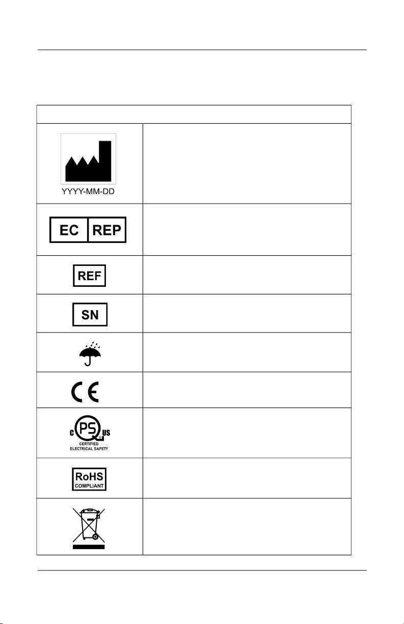
Symbols . . . . . . . . . . . . . . . . . . . . . . . . . . . . . . . . . . . . . . . . . . . . . . . . . . . . . . . . . . . . . .10
4. SPECIFICATIONS . . . . . . . . . . . . . . . . . . . . . . . . . . . . . . . . . . . . . . . . . . . 13
Dimensions . . . . . . . . . . . . . . . . . . . . . . . . . . . . . . . . . . . . . . . . . . . . . . . . . . . . . . . . . . .14
5. USING THE BRIDGE . . . . . . . . . . . . . . . . . . . . . . . . . . . . . . . . . . . . . . . . 15
Before Transfer . . . . . . . . . . . . . . . . . . . . . . . . . . . . . . . . . . . . . . . . . . . . . . . . . . . . . . . .15
Using the Bridge . . . . . . . . . . . . . . . . . . . . . . . . . . . . . . . . . . . . . . . . . . . . . . . . . . . . . .16
Manual Operation (electrical). . . . . . . . . . . . . . . . . . . . . . . . . . . . . . . . . . . . . . . . . .19
Manual Operation (mechanical) . . . . . . . . . . . . . . . . . . . . . . . . . . . . . . . . . . . . . . .20
6. MAINTENANCE . . . . . . . . . . . . . . . . . . . . . . . . . . . . . . . . . . . . . . . . . . . . 21
Recommended Operator Maintenance Schedule. . . . . . . . . . . . . . . . . . . . . . .21
Recommended Dealer Maintenance Schedule . . . . . . . . . . . . . . . . . . . . . . . . .22
Inspection and Cleaning . . . . . . . . . . . . . . . . . . . . . . . . . . . . . . . . . . . . . . . . . . . . . .23
7. TROUBLESHOOTING . . . . . . . . . . . . . . . . . . . . . . . . . . . . . . . . . . . . . . . 24
8. ELECTROMAGNETIC COMPATIBILITY. . . . . . . . . . . . . . . . . . . . . . . . 25
Electromagnetic Compliance . . . . . . . . . . . . . . . . . . . . . . . . . . . . . . . . . . . . . . . . . .25
Electromagnetic Immunity . . . . . . . . . . . . . . . . . . . . . . . . . . . . . . . . . . . . . . . . . . . .26

5
Part No. 001300-EN, 07-m01-2022 Ceiling Lift Track Bridge Owner’s Manual
1. OVERVIEW
Intended Use
The Track Bridge is designed for use by caregivers and health care professionals
to connect a mobile X-Y rail to a fixed rail together, thus allowing the portable
or fixed ceiling lift to move freely between both track routes in a homecare,
assisted-living or hospital environment. Transfer must be performed by a
qualified operator.
Product Life
The Bridge is designed for a useful life of 10 years after which time it must be
replaced. To ensure this life span, you must perform the preventive
maintenance as specified in the Maintenance section in this manual.
Savaria Concord Lifts, Inc. cannot ensure complete safety
for a track Bridge that has exceeded its useful life. Wear
may cause failure of a part and lead to a patient fall.
The expected life for other parts such as batteries, fuses, and cords are
dependent upon the proper care and use of the individual items. The items
must be maintained as described in their accompanying documentation and in
the Maintenance section in this manual.
Using This Manual
To ensure safe operation of the Bridge, read this entire manual carefully,
especially the Safety Instructions, before installing, using or maintaining the
Bridge. Failure to comply with all WARNINGS in this manual may result in injury.
If there is anything you don’t understand, contact your Authorized Savaria
Dealer for further details.
Keep this manual with the track Bridge and ensure all operators are fully trained
in the use of the Bridge as described in this manual.
WARNING

6
Ceiling Lift Track Bridge Owner’s Manual Part No. 001300-EN, 07-m01-2022
2. SAFETY INSTRUCTIONS
Keep these Safety Instructions with the track Bridge at all times. Read this entire
manual before installing, using or maintaining the track Bridge.
Do NOT use the track Bridge for any purpose other than to
transfer a person. To ensure safety of the person being
transferred and the operator, follow all Safety
Instructions.
To Ensure Safety
• The track Bridge has a safe working load of 272 kg (600 lb). Do NOT
exceed this load. Refer to the nameplate tag for the Maximum Load
allowed.
• Ensure the track Bridge is installed only with a Savaria ceiling track
system and used only with Savaria ceiling lifts.
• The track Bridge and track system must be installed by a trained and
Authorized Savaria Dealer.
• Operators must be fully trained before using the lift and Bridge.
• Take care to avoid impact during transfer.
• Keep all components of the device clean and dry.
• Perform the “Before each use” checks and actions specified in the
Operator Maintenance Schedule before using the device.
• Ensure all checks and actions are performed at the frequency indicated
in the Maintenance section in this manual.
WARNING

7
Part No. 001300-EN, 07-m01-2022 Ceiling Lift Track Bridge Owner’s Manual
Battery and Charger Safety
Contact your Authorized Savaria Dealer if you are unsure
of any of the safety instructions provided below.
• Do NOT expose the battery or charger to water or any other liquid.
• To avoid injury, do NOT alter the battery in any way. Stop using the
battery if any damage is noted.
• Do NOT charge the battery in an unventilated area and do not cover
the charger.
• If the battery case cracks and the contents of the battery contact your
skin or clothing, rinse immediately with plenty of water.
• If the contents of the battery contact your eyes, rinse immediately with
plenty of water and seek medical attention.
• Inhalation of the contents of the battery can cause respiratory
irritation. Provide fresh air and seek medical attention.
• For recycling or disposal of batteries, follow the rules according to the
WEEE directive (Waste of Electronic and Electrical Equipment) as well
as all local laws and regulations. If you do not follow these rules, the
battery may explode, leak and cause personal injury.
Shock Prevention
• Do NOT touch or use the device if you notice any exposed or damaged
wires.
• Do NOT expose electrical parts of the device to water or moisture.
• Do NOT attempt to use the charger in an area that has a different
voltage and frequency requirement other than that specified on the
nameplate.
• Do NOT attempt any repairs to the Bridge or power supply. Always
contact your Authorized Savaria Dealer for service.
WARNING

8
Ceiling Lift Track Bridge Owner’s Manual Part No. 001300-EN, 07-m01-2022
3. DESCRIPTION
Exterior View
The image below shows the Bridge uninstalled, viewed from below.
Figure 1
Note that the Bridge will only work with devices equipped with a magnetic
block as shown below. For magnetic block installation and kit assembly, refer to
the Track Installation section in the Track Installation Guide (001076).
Figure 2
ON/OFF switch
Magnetic block installed
on portable trolley when
used with portable lift
Magnetic block
installed on
fixed lift
Kit provided with the Bridge

9
Part No. 001300-EN, 07-m01-2022 Ceiling Lift Track Bridge Owner’s Manual
Device Controls
Figure 3
Charger
The Bridge is supplied with a battery charger as shown below. The Bridge is
connected to the constant charging system (CCR system) in the track. The
battery charger is external to the track system and it is intended to stay
connected to CCR at all times. The Bridge manages the battery charging
automatically as needed.
Figure 4
Indicator Meaning
1- Light OFF Device not connected to the charger -OR- power
failure -OR- device in use.
1- Amber (Solid) Device is connected to charging system.
2- Light OFF Device is OFF.
2- Green (Solid) Device is powered ON and ready.
2 - Green (Flashing) Device battery is low.
Note: An audible beep is emitted approximately every
minute in addition to the flashing indicator.
2- Red (Solid) Device malfunction (jammed, time-out, etc.).
3- Light OFF Device is ready for use.
3- Amber (Solid) Inspection required. Call Authorized Savaria Dealer.
LED Description
1. When ON, fully charged or disconnected = led is solid
green
2. When charging , led turns yellow, amber or red
(depending on the charger version)
3. Blinking/fading green = erroneous plugging sequence
(most likely to happen with the portable lift, on the
M920001-X only):
a. When this happens, user has to make sure that the
charger is powered (plugged to the wall) prior to
connect it to the lift.

10
Ceiling Lift Track Bridge Owner’s Manual Part No. 001300-EN, 07-m01-2022
Symbols
The following chart illustrates the symbols that may be used on the nameplate,
the packaging and the device.
Symbols on nameplate
Indicates the medical device manufacturer. This
symbol is accompanied by the address of the
manufacturer and the date of manufacture.
YYYY: Represents the year
MM: Represents the month
DD: Represents the day
Indicates the authorized representative in the
European Community.
This symbol is accompanied by the address of the
authorized representative.
Indicates the manufacturer's catalogue number
Indicates the manufacturer's serial number
Keep dry
Indicates the product complies with the medical
device directive
Indicates the product was certified by third-party
“QPS”
Indicates the product complies with the directive
(RoHS)
Indicates "separate collection" for all batteries and
accumulators per the WEEE directive

11
Part No. 001300-EN, 07-m01-2022 Ceiling Lift Track Bridge Owner’s Manual
Direct current
Caution
Refer to instruction manual/booklet
Consult instructions for use
Type BF protection against electrical shocks
MAX.LOAD:
Refers to the greatest permissible load that can be
applied to the product
IPX1X2
Ingress Protection:
X1: Protection level against ingress of solid particles
X2: Protection level against ingress of liquids
Unique Device Identification (UDI) symbol required
by the FDA
Indicates the product is a medical device according
to EU Medical Device Regulation 2017/745

12
Ceiling Lift Track Bridge Owner’s Manual Part No. 001300-EN, 07-m01-2022
Symbols on box label
Indicates the temperature limits to which the
medical device can be safely exposed
Indicates the range of humidity to which the
medical device can be safely exposed
Indicates the range of atmospheric pressure to
which the medical device can be safely exposed
Symbols on device
Indicates that the device is on charge or charged
Indicates the power status
Indicates that maintenance is recommended on the
device

13
Part No. 001300-EN, 07-m01-2022 Ceiling Lift Track Bridge Owner’s Manual
4. SPECIFICATIONS
Product
Product Weight 9.8 kg (21.6 lb)
Product Life 10 years
Safe Working Load (SWL) 272 kg (600 lb)
Water Ingress Protection
Rating of Device
IP21
Noise Level Maximum 54 dBA
Medical Electrical
Equipment Class
Class 1
Protection Class Type BF
Power Source
Input 100-240 VAC, 50-60Hz
Output 29.4 VDC, max 1A
Battery Battery type: Lithium Ion, 25.2V, 2500mAh
Environmental Conditions
Operating Temperature 5 °C to 40 °C (41 °F to 104 °F)
Battery Charging
Temperature
10 °C to 40 °C (50 °F to 104 °F)
Operating Humidity 15 to 93%, non-condensing
Storage Temperature -25 °C to 70 °C (-13 °F to 158 °F)
Storage Humidity 0 to 93%, non-condensing
Atmospheric Pressure 70 kPa to 106 kPA
WARNING: This equipment is not suitable in the presence of flammable
anesthetic mixtures with air or oxygen, or with nitrous oxide.
Controls
Control Lift presence detected by magnetic sensor
Compliance
IEC 60601-1:2005 A1:2012+A2:2020 (Medical Electrical Equipment)
IEC 60601-1-11:2015 (Homecare)
ISO 10535:2006
CAN/CSA Z10535.1:15

14
Ceiling Lift Track Bridge Owner’s Manual Part No. 001300-EN, 07-m01-2022
Dimensions
Compliance
CE Marking per MDR (EU) 2017/745 (Medical Device)
2006/42/EC (Machinery Directive)
2015/863/EU (ROHS - 100% of components)
2012/19/EU (WEEE)

15
Part No. 001300-EN, 07-m01-2022 Ceiling Lift Track Bridge Owner’s Manual
5. USING THE BRIDGE
Before Transfer
• The Bridge has built-in stoppers that automatically close when the
device is disengaged. Ensure these stoppers are in correct position.
• Any track extremities other than the extremities blocked by the Bridge
shall have end stops securely in place as shown below.
• Inform the person to be transferred what you are about to do. The
beep and the locking process can cause stress if the process is
unknown.
Figure 5
TRACK END STOP

16
Ceiling Lift Track Bridge Owner’s Manual Part No. 001300-EN, 07-m01-2022
Using the Bridge
1Move the ceiling lift inside the Bridge.
Figure 6
2Move the mobile Bridge (Primary) in front of the fixed Bridge (Secondary).
You will hear a beep confirming that the Bridge is positioned correctly.
Figure 7
3After less than two seconds, the Bridge will automatically become engaged.

17
Part No. 001300-EN, 07-m01-2022 Ceiling Lift Track Bridge Owner’s Manual
4Move the lift across the fixed Bridge (Secondary) and into the track. The
bridges will remain locked together until the lift returns and crosses the
bridge to go back into the mobile track.
Figure 8

18
Ceiling Lift Track Bridge Owner’s Manual Part No. 001300-EN, 07-m01-2022
5To disengage the Bridge, move the lift across both Bridges for it to
automatically disconnect.
Figure 9
Figure 10

19
Part No. 001300-EN, 07-m01-2022 Ceiling Lift Track Bridge Owner’s Manual
Do NOT move the lift by pulling the hand control. The
handset may spring return and cause injuries.
NEVER leave a person unattended during a transfer to
prevent the person from falling and sustaining possible
injuries.
Manual Operation (electrical)
In the unlikely event of Bridge failure, you can use the bypass button to
manually operate the Bridge.
Figure 11
CAUTION
WARNING

20
Ceiling Lift Track Bridge Owner’s Manual Part No. 001300-EN, 07-m01-2022
Manual Operation (mechanical)
In the unlikely event of Bridge failure, you can use a 4mm Allen Key to manually
operate the Bridge.
Figure 12
Table of contents
Other Savaria Lifting System manuals

Savaria
Savaria K2 User manual

Savaria
Savaria M2LIFT User manual

Savaria
Savaria V1504 User manual

Savaria
Savaria Stairfriend User manual

Savaria
Savaria Track Bridge User manual

Savaria
Savaria PL User manual

Savaria
Savaria V1504 User manual

Savaria
Savaria Multilift Technical manual

Savaria
Savaria M2LIFT-40 User manual

Savaria
Savaria M-1504 User manual
Popular Lifting System manuals by other brands

Aqua Creek Products
Aqua Creek Products F-411RPL-AT1-02 manual

Smiley Lifting Solutions
Smiley Lifting Solutions URW706 quick start guide

Lift Tek
Lift Tek 80D-MS Service manual

Titan Lifts
Titan Lifts Master Series Installation, operation & maintenance manual

Vestil
Vestil FE Series manual

probst
probst SH-2500-UNI-B operating instructions