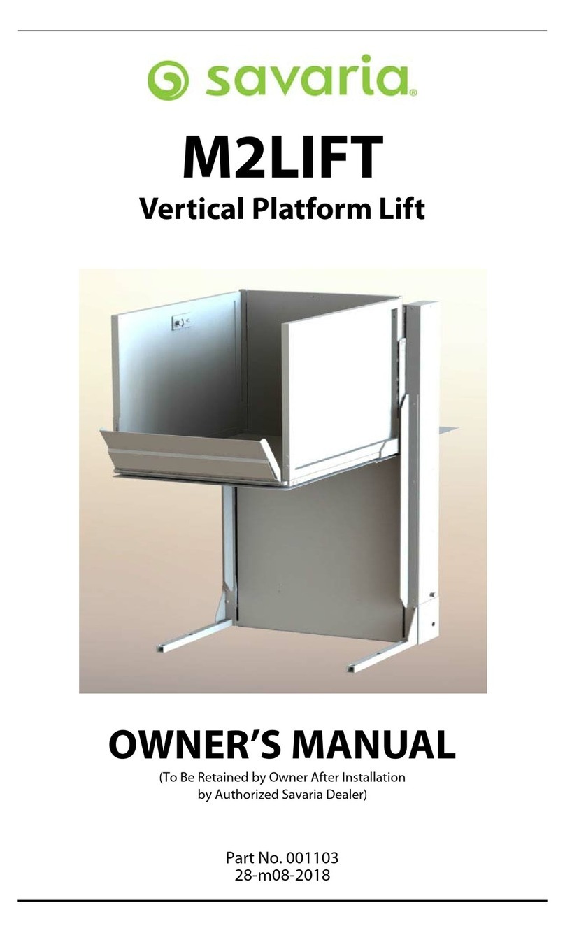
Savaria M2LIFT User manual

M2Lift
Vertical
Platform Lift
Owner’s
Manual

IMPORTANT – READ FIRST
Ensure that only an authorized Savaria mechanic installs and services your
Lift. Under no circumstances is anyone other than a mechanic with Savaria
training and authorization to install, adjust, service or modify any mechanical
or electrical device on this equipment.
Failure to follow this warning can result in safety system compromises or
defeat; this can result in serious injury or death. Savaria accepts no liability for
property damage, warranty claims or personal injury, including death, in this
circumstance.
Passenger safety is the result of countless details in the equipment design,
manufacture, and installation. After installation, reliable operation and
continual safe operation requires regular inspection and maintenance as
outlined in this manual, or more frequently where usage, environment, or
local jurisdiction requires. As the Owner, you are responsible for ensuring
that regular inspections and maintenance occur in a timely manner as per the
manufacturer’s recommendations and maintenance schedule.
Refer to this owner’s manual for unit description, setup, operating instructions,
and a maintenance schedule for your Lift. Upon completion of installation, the
Savaria mechanic must provide you with the information for the box below
and ensure it is recorded in this owner’s manual. In addition, either you or the
Savaria mechanic must keep any service and/or maintenance records in the
Maintenance Record section of this owner’s manual.
At all times, your Lift must be maintained in compliance with the applicable
standard to which it has been built and installed
United States: A18.1–Safety Standard for Platform Lifts and Stairway Chairlift
Canada: CSA B355/613–Platform lifts and stair lifts for barrier-free access
Europe: EN-81-40–Stairlifts and inclined lifting platform intended for persons
with impaired mobility
Europe: 2006/42/EC–Machinery Directive
Depending on your country or region, the local authority code variant
may apply. To ensure safe operation of your Lift, pay careful attention to
the important notes, and follow the instructions and any additional safety
regulations in this manual.
FOR OWNER’S RECORDS
Customer Name:
Installing Dealer:
Dealer’s Telephone Number:
Date Installed:
Serial/Job Number:

-------------------------------------------------------------------------------------------------
3
WARRANTY
Ensure your Savaria Dealer provides you with acopy of the manufacturer’s
limited parts warranty and documentation relating to any Dealer labour
warranty.
CONTENTS
TO ENSURE SAFE OPERATION . . . . . . . . . . . . . . . . . . . . . . . . . . . . . . . . . . . . . . . . . . . . . .4
1. DESCRIPTION . . . . . . . . . . . . . . . . . . . . . . . . . . . . . . . . . . . . . . . . . . . . . . . . . . . . . . . . . . .5
2. GENERAL SPECIFICATIONS . . . . . . . . . . . . . . . . . . . . . . . . . . . . . . . . . . . . . . . . . . . . . .6
3. OPERATION . . . . . . . . . . . . . . . . . . . . . . . . . . . . . . . . . . . . . . . . . . . . . . . . . . . . . . . . . . . . .7
Attendant Operation . . . . . . . . . . . . . . . . . . . . . . . . . . . . . . . . . . . . . . . . . . . . . .7
Operating from the COP Controls . . . . . . . . . . . . . . . . . . . . . . . . . . . . . . . . .7
Operating from the Landing Station Controls . . . . . . . . . . . . . . . . . . . . .8
4. ADDITIONAL FEATURES . . . . . . . . . . . . . . . . . . . . . . . . . . . . . . . . . . . . . . . . . . . . . . . .10
Safety Underpan . . . . . . . . . . . . . . . . . . . . . . . . . . . . . . . . . . . . . . . . . . . . . . . .10
Gate Lock . . . . . . . . . . . . . . . . . . . . . . . . . . . . . . . . . . . . . . . . . . . . . . . . . . . . . . .11
Safety Brake . . . . . . . . . . . . . . . . . . . . . . . . . . . . . . . . . . . . . . . . . . . . . . . . . . . . .11
Emergency Stop Button . . . . . . . . . . . . . . . . . . . . . . . . . . . . . . . . . . . . . . . . .11
Battery Lowering . . . . . . . . . . . . . . . . . . . . . . . . . . . . . . . . . . . . . . . . . . . . . . . .11
5. MAINTENANCE . . . . . . . . . . . . . . . . . . . . . . . . . . . . . . . . . . . . . . . . . . . . . . . . . . . . . . . .12
Maintenance Schedule . . . . . . . . . . . . . . . . . . . . . . . . . . . . . . . . . . . . . . . . . .12
Operator Troubleshooting . . . . . . . . . . . . . . . . . . . . . . . . . . . . . . . . . . . . . . .14
Maintenance Record . . . . . . . . . . . . . . . . . . . . . . . . . . . . . . . . . . . . . . . . . . . .15
Part No. 001103, 10-m08-2021 M2LIFT Owner’s Manual

4
TO ENSURE SAFE OPERATION
To ensure safe operation of this equipment, pay careful attention to the
important notes below.
•Read this manual carefully before using the equipment.
•To prevent accidents, adhere strictly to the instructions and keep clear
of moving parts at all times.
•Follow instructions on all equipment labels at all times. Replace any
damaged labels immediately.
•Ensure that only qualified personnel perform maintenance and service
on the unit.
•When replacing parts, be sure that only genuine Savaria parts are used.
•This unit is intended for use by amature person who understands its
proper operation as set out in this manual.
WARNING
At no time should children under the age of 16 use the lift
while unsupervised.
•Prior to operation, make sure that:
•All doors and gates are locked and secure.
•All areas in and around the lift are clear of any obstructions.
•All lights are functioning properly.
•Test your keys and emergency stop button every month.
M2LIFT Owner’s Manual Part No. 001103, 10-m08-2021

5
1. DESCRIPTION
Figure 1shows the exterior components of the M2LIFT.
Figure 1
Car operating Tower rail cap
panel (COP) Landing gate
COP
side wall
Tower
Landing
sill
Opposite
side wall
Access ramp
Fascia
Non-skid platform panel
Motor
cover
Pit switch
Safety underpan
Base support legs
Part No. 001103, 10-m08-2021 M2LIFT Owner’s Manual

6
2. GENERAL SPECIFICATIONS
Load capacity 750 lb (340 kg)
Maximum travel M2LIFT-40: 42” (1067 mm)
M2LIFT-60: 62” (1575 mm)
M2LIFT-75: 77” (1956 mm)
Minimum travel 15.5” (394 mm)
Levels serviced 2
Nominal speed 9ft/min (0.046 m/s)
Daily cycle
Normal: 10
Heavy: 25
Excessive: 40
Maximum starts in 1hour on standard installation: 5
Platform size 37 1/8” x 54 1/8” (9443 mm x1375 mm)
Side wall height 42” (1067 mm)
Access Front/rear access (type 2cab)
Power supply 120 VAC, 15A, 60 Hz, single phase
Drive system Direct drive gear
Chain suspension
Motor 24 VDC, 1.3 HP, geared
Controller LUT125 PCB
Finish Electrostatic powder coat paint on all metallic surfaces and
vacuumed formed plastics
Standard features
24VDC operation
Wireless call/send stations at landings
Constant-pressure type buttons
Operating control buttons on platform
Automatic battery recharging system (115 VAC)
Low-voltage controls
Limit switches
Non-skid platform surface
Automatic access ramp
Emergency stop button (E-stop on COP) and alarm
Pit switch (E-stop on tower)
Safety underpan
Motor safety brake
Battery lowering
Outdoor package
M2LIFT Owner’s Manual Part No. 001103, 10-m08-2021

7
3. OPERATION
IMPORTANT
Prior to operating the lift, amanual wheelchair MUST have
the wheels locked and any power-operated device MUST
have the power turned off.
NOTE
Position the wheelchair, scooter or walker CENTRAL on the platform.
Attendant Operation
•The attendant shall only operate the lift from the call station located at
the lower landing if the lift is unenclosed.
•The attendant shall have full view of the floor area under the lift and of
the rider at all times.
•If the lift is enclosed, the lift can be operated from the upper landing
provided the operator has aview of the rider at all times.
•During attendant operation, the car directional controls must not be
operational.
Operating from the COP Controls
Figure 2shows the car operating panel (COP).
Figure 2
Emergency
Key Switch
Up/Down
Stop
To operate the lift from the COP controls:
Part No. 001103, 10-m08-2021 M2LIFT Owner’s Manual

8
1Insert the key into the key switch and turn it to the ON position to activate
the operating buttons.
2Apply constant pressure on the Up/Down button (as required) to move the
platform to the desired landing. Note that the lift will not move if the gate is
open.
3When the lift reaches the landing, the gate will unlock automatically. If you
need to re-open the door after adelay, turn the key to the ON position and
press the call button again to unlock the gate.
4To prevent unauthorized use of the lift, take the key out when the unit is not
in operation.
5Pressing the Emergency Stop button during travel will stop the lift
immediately and activate the alarm. The Emergency Stop overrides the
landing station controls. Pull the Emergency Stop out to return the lift to
normal operation.
6If the gate is locked at alanding for more than 10 seconds, you can press the
Up button to unlock the gate.
Operating from the Landing Station Controls
Figure 3shows the landing station (hall call).
Figure 3
Key switch
Landing
buttons
Surface Mount
To operate the lift from the landing (call/send) station controls:
1Insert the key into the key switch and turn it to the ON position to activate
the operating buttons.
M2LIFT Owner’s Manual Part No. 001103, 10-m08-2021

9
2Press the appropriate landing button to move the platform to the desired
landing. Note that the lift will not move if the gate is open.
3When the lift reaches the landing, the door will unlock automatically. If you
need to re-open the door after the delay, turn the key on and press the call
Up button again to unlock the door.
4To prevent unauthorized use of the lift, take the key out when the unit is not
in operation.
Part No. 001103, 10-m08-2021 M2LIFT Owner’s Manual

10
4. ADDITIONAL FEATURES
Safety Underpan
The safety underpan (shown in Figure 4) is located under the platform. The
underpan has sensors that detect any obstacles and stop the downward travel
of the lift. This is optional on enclosed units and required on open hoistways.
Figure 4
Safety Underpan
M2LIFT Owner’s Manual Part No. 001103, 10-m08-2021

11
Gate Locks
The WR-500 gate lock keeps the gate locked when the platform is moving and
not at alanding.
NOTE
Keys are for emergency use only and should always be kept in asafe
place for use by trained personnel only. After use of any emergency
function (access key or manual lowering device), ensure that all
doors/gates are secure and locked. While the emergency function is in
use, DO not leave the area unattended.
Emergency Gate Opening Figure 5
The gate can be opened manually using the
emergency key provided for the WR-500 lock (Figure 5).
Insert the key into the lock and turn it ahalf turn
clockwise to unlock the gate. Pull the gate open and
then turn the key ahalf turn counter-clockwise to
remove it from the lock. DO NOT open the gate if there
is any chance of falling from the platform.
Safety Brake
+EY0.
The motor Safety Brake stops the platform in the
event of achain failure.
During normal operation, the chain tension keeps the
brake mechanism up so the brake cam does not
interfere with the tower guide rail. If achain failure
occurs, the brake mechanism activates and stops the
platform.
Emergency Stop Button
Pressing the red Emergency Stop button during travel will stop the lift
immediately and activate the alarm. The Emergency Stop overrides the landing
(call/send) stations. Be sure to pull the Emergency Stop button out to return the
lift to normal operation.
Battery Lowering
In the event of apower failure, press the DOWN button to bring the lift to the
lower level.
Part No. 001103, 10-m08-2021 M2LIFT Owner’s Manual

12
5. MAINTENANCE
NOTE
Regular maintenance (performed by your Authorized Savaria
Dealer) will keep your unit in proper operating condition. As the
owner of this unit, you are responsible for making sure that
maintenance and upkeep are done on aregularly scheduled
basis. To ensure proper operating condition of your unit, the
items listed below must be performed every 6months by an
Authorized Savaria Dealer.
Additional inspections may be required depending on usage.
Units installed in adverse environments will require additional
maintenance on amonthly basis..
DANGER
Technicians must always ensure the lift is safely shored when
working under the platform.
Maintenance Schedule
Verification Frequency
Verify general operation of the lift. Every 2months
Verify correct operation of the underpan sensors. Every 2months
Verify correct operation of the emergency stop. Every 2months
Verify correct operation of the gate lock contacts. The lift
should not run unless the gate is closed and locked. Every 2months
Verify the general operation of the lift. Every 6months
Check the chains in the suspension system. Every 6months
Check the connecting links in the suspension system. Every 6months
Check the chain pulleys and shafts in the suspension system. Every 6months
Check the parts holding the chains on the roller supports in
the suspension system. Every 6months
M2LIFT Owner’s Manual Part No. 001103, 10-m08-2021

13
Maintenance Schedule (continued)
Verification Frequency
Check the chain tensioners on the rail in the suspension
system. The tensioners must be tight. Every 6months
Verify that all hardware is tightened. Every 6months
Check the safety brake. Every 6months
Check the rollers (function and wear). Every 6months
Ensure that all filler panels are securely fastened in the gate. Every 6months
Part No. 001103, 10-m08-2021 M2LIFT Owner’s Manual

14
Operator Troubleshooting
The following table lists potential problems and their possible solutions.
If the problem persists, contact your Authorized Dealer.
Potential Problem Possible Solution
Platform goes up but does not
come down
Check the underpan sensors. Pull down on the
underpan to ensure the pan is not stuck in the
activated position.
Platform comes down but does
not go up Check that the power cord is plugged in.
Platform does not move
Check that the key is ON.
Check that the gate is closed.
Check to see if the Emergency Stop buttons (on
the COP and tower) are pushed in; they must be
pulled out for normal operation.
If the platform is at the top landing, check the
underpan sensors as described above.
Check that the power cord is plugged in.
M2LIFT Owner’s Manual Part No. 001103, 10-m08-2021

Maintenance Record
Date Time Reason for call Comments Dealer

M2Lift
Vertical Platform Lift
Owner’s Manual
For service or questions about this product,
please contact your installing dealer.
Dealer Name:
Dealer Phone:
Authorized Savaria Dealer
Savaria Concord Lifts, Inc.
2 Walker Drive Brampton ON L6T 5E1 Canada savaria.com
Part No. 001103 ©2021 Savaria Corporation
Other manuals for M2LIFT
1
Table of contents
Other Savaria Lifting System manuals

Savaria
Savaria M2LIFT-40 User manual

Savaria
Savaria omega User manual

Savaria
Savaria Multilift Technical manual

Savaria
Savaria V1504 User manual
Savaria
Savaria Step-Saver User manual

Savaria
Savaria V1504 User manual

Savaria
Savaria M-1504 User manual

Savaria
Savaria Track Bridge User manual

Savaria
Savaria Stairfriend User manual

Savaria
Savaria PL User manual
Popular Lifting System manuals by other brands

rav
rav KPH 370.40EX Translation of the original instructions

ShoreDocker
ShoreDocker SD1200 Assembly and operating instructions

Kval
Kval ON-3V Operation manual

Linde
Linde 120x Original instructions

HIRD GLASS
HIRD GLASS KAPPEL HYDRAULICA 2000 Operator's manual

Ludewig
Ludewig Climber M installation instructions