Savo 90575 User manual

90575
92575
Instructions Manual
Käyttöohje

2
2
INDEX
RECOMMENDATIONS AND SUGGESTIONS..................................................................................................................... 3
CHARACTERISTICS.............................................................................................................................................................6
INSTALLATION...................................................................................................................................................................... 8
USE...................................................................................................................................................................................... 12
MAINTENANCE...................................................................................................................................................................13
SISÄLTÖ
OHJEET JA SUOSITUKSET............................................................................................................................................... 15
MITAT JA OSAT .................................................................................................................................................................. 18
ASENNUS............................................................................................................................................................................ 20
KÄYTTÖ............................................................................................................................................................................... 24
HUOLTO .............................................................................................................................................................................. 25
EN
FI

EN 3
3
RECOMMENDATIONS AND SUGGESTIONS
The Instructions for Use apply to several versions of this appliance.
Accordingly, you may find descriptions of individual features that do not
apply to your specific appliance.
INSTALLATION
• The manufacturer will not be held liable for any damages resulting from
incorrect or improper installation.
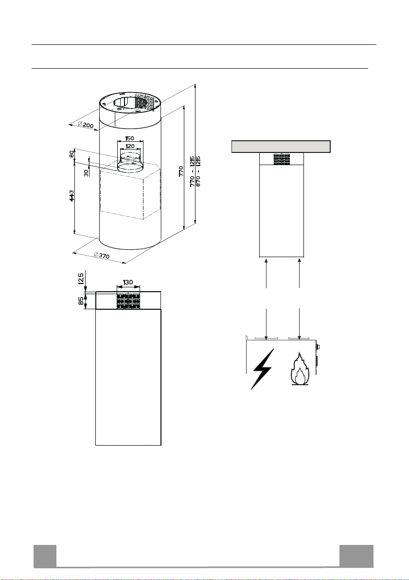
• The minimum safety distance between the cooker top and the extractor hood
is 650 mm (some models can be installed at a lower height, please refer to
the paragraphs on working dimensions and installation).
• Check that the mains voltage corresponds to that indicated on the rating
plate fixed to the inside of the hood.
• For Class I appliances, check that the domestic power supply guarantees
adequate earthing.
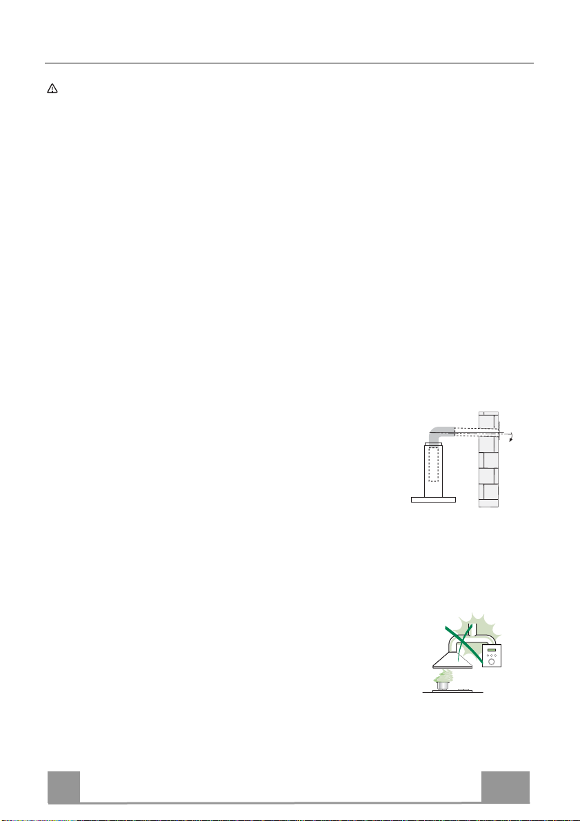
Connect the extractor to the exhaust flue through a pipe of minimum
diameter 120 mm. The route of the flue must be as short as possible.
• Do not connect the extractor hood to exhaust ducts
carrying combustion fumes (boilers, fireplaces, etc.).
• If the extractor is used in conjunction with non-electrical
appliances (e.g. gas burning appliances), a sufficient
degree of aeration must be guaranteed in the room in
order to prevent the backflow of exhaust gas. The
kitchen must have an opening communicating directly
with the open air in order to guarantee the entry of clean air. When the
cooker hood is used in conjunction with appliances supplied with energy
other than electric, the negative pressure in the room must not exceed 0,04
mbar to prevent fumes being drawn back into the room by the cooker hood.
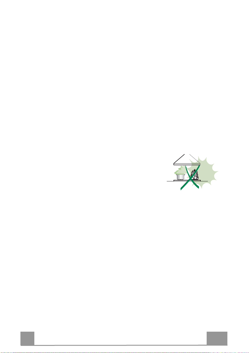
• The air must not be discharged into a flue that is used for
exhausting fumes from appliances burning gas or other
fuels (not applicable to appliances that only discharge the
air back into the room).
• In the event of damage to the power cable, it must be
replaced by the manufacturer or by the technical service
department, in order to prevent any risks.
2°

EN 4
4
• If the instructions for installation for the gas hob specify a greater distance
specified above, this has to be taken into account. Regulations concerning
the discharge of air have to be fulfilled.
• Use only screws and small parts in support of the hood.
Warning: Failure to install the screws or fixing device in accordance with
these instructions may result in electrical hazards.
• Connect the hood to the mains through a two-pole switch having a contact
gap of at least 3 mm.
USE
• The extractor hood has been designed exclusively for domestic use to
eliminate kitchen smells.
• Never use the hood for purposes other than for which it has been designed.
• Never leave high naked flames under the hood when it is in operation.
• Adjust the flame intensity to direct it onto the bottom of the pan only, making
sure that it does not engulf the sides.
• Deep fat fryers must be continuously monitored
during use: overheated oil can burst into flames.
• Do not flambè under the range hood; risk of fire.
• This appliance can be used by children aged from
8 years and above and persons with reduced
physical, sensory or mental capabilities or lack of
experience and knowledge if they have been given supervision or instruction
concerning use of the appliance in a safe way and understand the hazards
involved. Children shall not play with the appliance. Cleaning and user
maintenance shall not be made by children without supervision.
• This appliance is not intended for use by persons (including children) with
reduced physical, sensory or mental capabilities, or lack of experience and
knowledge, unless they have been given supervision or instruction
concerning use of the appliance by a person responsible for their safety.

EN 5
5
• “CAUTION: Accessible parts may become hot when used with cooking
appliances.”
MAINTENANCE
•Switch off or unplug the appliance from the mains supply before carrying out
any maintenance work.
• Clean and/or replace the Filters after the specified time period (Fire hazard).
• The Grease filters must be cleaned every 2 months of operation, or more
frequently for particularly heavy usage, and can be washed in a dishwasher.
• The Activated charcoal filter is not washable and cannot be regenerated,
and must be replaced approximately every 4 months of operation, or more
frequently for particularly heavy usage.
• "Failure to carry out cleaning as indicated will result in a fire hazard".
• Clean the hood using a damp cloth and a neutral liquid detergent.
The symbol on the product or on its packaging indicates that this product
may not be treated as household waste. Instead it shall be handed over to the
applicable collection point for the recycling of electrical and electronic
equipment. By ensuring this product is disposed of correctly, you will help
prevent potential negative consequences for the environment and human
health, which could otherwise be caused by inappropriate waste handling of
this product. For more detailed information about recycling of this product,
please contact your local city office, your household waste disposal service or
the shop where you purchased the product.

EN 6
6
CHARACTERISTICS
Dimensions
*
**
Min.
550mm
Min.
550mm
* Dimensions of the hood in ducting version.
** Dimensions of the hood in recycling version.

EN 7
7
Components
Ref. Q.ty Product Components
11 Hood Body, complete with: Controls, Light, Blower,
Filters
21 Chimney Upper
7.1 1 Telescopic frame complete with extractor, consisting
of:
7.1a 1 Upper frame
7.1b 1 Lower frame
91 Reducer Flange ø 150-120 mm
10 1 Flange ø 120 mm
10a 1 Dumper
15 1 Recirculation Air Outlet Connection
25 2 Pipe clamps (not included)
Ref. Q.ty Installation Components
11 4 Wall Plugs ø 10
12c 4 Screws 2,9 x 6,5
12f 4 Screws M6 x 10
12g 4 Screws M6 x 80
12h 4 Screws 5,2 x 70
21 1 Drilling template
22 4 6.4 mm int. dia washers
23 4 M6 nuts
Q.ty Documentation
1 Instruction Manual
2
11
12h
22
23
21
7.1
1
12g
9
25
7.1a
7.1b
15
12f
10
12c
10a

EN 8
8
INSTALLATION
Drilling the Ceiling/shelf and fixing the frame
DRILLING THE CEILING/SHELF
• Use a plumb line to mark the centre of the hob on the ceiling/support shelf.
• Place the drilling template 21 provided on the ceiling/support shelf, making sure that the
template is in the correct position by lining up the axes of the template with those of the hob.
• Mark the centres of the holes in the template.
• Drill the holes at the points marked:
• For concrete ceilings, drill for plugs appropriate to the screw size.
• For hollow brick ceilings with wall thickness of 20 mm: drill ø 10 mm(immediately insert
the Dowels 11 supplied).
• For wooden beam ceilings, drill according to the wood screws used.
• For wooden shelf, drill ø 7 mm.
• For the power supply cable feed, drill ø 10 mm.
• For the air outlet (Ducted Version), drill according to the diameter of the external air ex-
haust duct connection.
• Insert two screws of the following type, crossing them and leaving 4-5 mm from the ceiling:
• For concrete ceilings, use the appropriate plugs for the screw size (not provided).
• for Cavity ceiling with inner space, with wall thickness of approx. 20 mm, Screws 12h,
supplied.
• For wooden beam ceilings, use 4 wood screws (not provided).
• For wooden shelf, use 4 screws 12g with washers 22 and nuts 23, provided.

EN 9
9
PREPARATION OF THE FRAME FOR THE HOOD
IN RECYCLING VERSION
In case the hood is used in recycling version it is
necessary to prepare the frame with all the nec-
essary connection pieces. In order to make the
installation easier it is necessary to lengthen the
frame:
• Unscrew the two screws 2.1 fixing the upper
chimney to the frame and pull the chimney
out.
• Unscrew the four safety screws placed at the
top in the frame separation area. (A).
• Unscrew the eight metric screws connecting
the two columns, placed on both sides of the
frame (B).
Installation of components in recycling version:
• Fix the recycling air outlet piece 15 to the up-
per part of the frame using four 12c screws
supplied with the hood.
• Fix the flange (ø120) 10 to the lower part of
the recycling air outlet 15.
• Put the reducer flange 9on the hood body
outlet.
• At this point, join the flanges with a pipe. In
order to calculate the height of the pipe it is
necessary to estimate the height of the hood
(mm) and subtract 615 mm. (H pipe = H
hood-615).
• Lengthen the frame so that the pipe can be
inserted. Place the pipe between the two
flanges and block it. Make sure that the height
of the frame is correct considering the height
of the cooker hood (H frame = H hood – 184).
Adjust the height of the frame and tighten
again the earlier removed screws. Tighten
again the safety screws in order to give more
stability to the structure.
• Fix the pipe with the pipe clamps 25 supplied
with the hood.
A
B
15
12c
10

EN 1
10
FIXING THE FRAME
• Lift the frame up, making sure that the index over the
frame plate is turned forwards.
• Fit the frame slots onto the two screws inserted in the
ceiling as above, and turn until reaching the centre of
the adjustment slot.
• Tighten the two screws and fasten the other two
screws provided; before locking the screws com-
pletely, it is possible to adjust the frame by turning it,
making sure that the screws do not come out of their
housing in the adjustment slot.
• The Frame must be securely fastened so as to support
both the weight of the Hood and the stress caused by
occasional axial pressure against the fitted Appliance.
After fixing, make sure that the base is stable even
when the Frame is subjected to lateral stress.
• If the Ceiling is not strong enough in the area where
the hood is to be fixed, the Installer must strengthen
the area using suitable plates and counterplates an-
chored to resistant structures.
2
112
Connections
DUCTED VERSION AIR EXHAUST SYSTEM
When installing the ducted version, connect the hood to
the chimney using either a flexible or rigid pipe ø 150 or
120mm, the choice of which is left to the installer.
To install a ø 150
• To install the dumper 10a.
• Fix the pipe in position using sufficient pipe clamps
(not supplied).
To install a ø 120
• To install a ø 120 mm air exhaust connection, insert
the reducer flange 9on the dumper 10a.
• Fix the pipe in position using sufficient pipe clamps
(not supplied).
• Remove any activated charcoal filters.
9
ø 120
ø 150
10a
10a

EN 1
11
Installing of the chimney and fixing of the hood
When the hood is installed in recycling version the chimney
has to be positioned with the slots upwards. When the hood
is installed in ducting version it has to be positioned in the
opposite way.
• Place the chimney on the frame and fix it to the upper
part of it with the earlier removed screws. When install-
ing the hood in recycling version make sure that the slots
correspond to the air outlet of the recycling air outlet
piece 15.
• Open the lighting unit by slightly pulling the notch. Re-
move the unit from the hood by sliding the fixing pivot.
• Remove the filter pushing it towards the back side of the
hood unit and simultaneously pulling downwards.
• Remove possible charcoal filters.
• In order to fix the hood body to the frame insert the 4
screws 12f in their seats. It is necessary to leave at least
4-5 mm gap between the screw heads and the frame plate.
• Hook the hood canopy to the frame and turn it to the left
until it reaches the stop, then lock the screws immediately
to prevent the hood canopy from falling out accidentally.
2
1
ELECTRICAL CONNECTION
• Connect the Hood to the mains power supply, inserting a
two-pole cut-out switch with contact aperture of at least 3
mm along the line.
• Ensure that the supply cable connector is properly in-
serted into the Suction device socket
• Hook up the Commands connector Cmd.
• Hook up the Spotlights connector Lux to the socket pro-
vided behind the lighting unit cover.
• For the Recirculation Version, fit the Activated Charcoal
Odour Filter.
• Replace the filters and the lighting unit.
Cmd
Lux

EN 1
12
L
T1
T2
T3
T4
S1
L
S1
T1 T2 T3 T4
LT3
S1
T2
T1 T4
USE
Control panel
Button Led Function
L- Turns the lights on/off at maximum strength.
T1 Fixed Turns the motor on/off at speed one.
Fixed Turns the Motor on at speed two.
T2
- Press and hold the button for approximately 3 seconds, with all the loads turned
off (Motor and Lights), to turn the Activated Charcoal Filter alarm on. The
relevant LED flashes twice to confirm.
To turn the alarm off, press the button again and hold for at least 3 seconds. The
relevant LED flashes once.
Fixed Turns the Motor on at speed three.
T3
- Press and hold the button for approximately 3 seconds, with all the loads turned
off (Motor and Lights), to perform a reset of Filter saturation alarm. The LED S1
flashes three times.
Fixed Turns the Motor on at INTENSIVE Speed.
This speed is timed to run for 6 minutes. At the end of this time, the system
returns automatically to the speed that was set before. If it is activated with the
motor turned off, the hood will switch to OFF at the end of the time.
T4
- Press and hold for 3 seconds to enable the remote control, indicated by the LED
flashing twice.
Press and hold for 3 seconds to disable the remote control, indicated by the LED
flashing just once.
Fixed Signals the Metal Grease Filter saturation alarm, indicating that it is necessary to
wash the filters. The alarm is triggered after the Hood has been in operation for
100 working hours.
S1
Flashing When this is activated, it signals the Activated Charcoal Filter saturation alarm,
indicating that the filter must be changed; the Metal Grease Filters must also be
washed. The Activated Charcoal Filter saturation alarm comes into operation after
the Hood has been working for 200 hours.

EN 1
13
MAINTENANCE
REMOTE CONTROL (OPTIONAL)
The appliance can be controlled using a remote control pow-
ered by a 1.5 V carbon-zinc alkaline batteries of the standard
LR03-AAA type (not included).
• Do not place the remote control near to heat sources.
• Used batteries must be disposed of in the proper manner.
Grease filters
CLEANING METAL SELF- SUPPORTING GREASE FILTERS
Alarm signal reset
• Switch off the lights and extractor motor.
• Press button T3 for at least 3 seconds, until the leds start to
flash.
Cleaning the filters
• The filters are washable and must be cleaned when the
LED S1 lights up or at least every 2 months of operation,
or more frequently for particularly heavy usage.
• Open the lighting unit by pulling on the nocth.
• Remove the filters one at a time by pushing them towards
the back of the group and pulling down at the same time.
• Wash the filters, taking care not to bend them. Allow them
to dry before refitting.
• When refitting the filters, make sure that the handle is visi-
ble on the outside.
• Replace the lighting unit.

EN 1
14
Activated Charcoal Filter (Recirculation Version)
This cannot be washed or regenerated, and must be changed when led S1 starts to flash, or at
least once every 4 months. The Alarm signal, if it has been activated, only appears when the
Suction motor is turned on.
Activating the alarm signal
• In Recirculation Version Hoods, the Filter Saturation Alarm must be activated on installa-
tion or at a later date.
• Turn the Lights and the Suction Motor off.
• Press button T2 and hold it for 5 seconds until the LED flashes twice in confirmation:
CHANGING
Resetting the alarm signal
• Turn the Lights and the Suction Motor off.
• Press T3 and hold for at least 3 seconds, until LED flashes
three times in confirmation.
Changing the Filter
• Open the lighting unit by pulling on the notch provided.
• Remove the Metal Grease Filter
• Remove the saturated Activated charcoal filter, using the hooks
provided.
• Fit the new Filter, hooking it into place.
• Fit the Grease filter and the Light Unit back into place.
Lighting unit
• For replacement contact technical support ("To purchase
contact technical support").

FI 1
15
OHJEET JA SUOSITUKSET
Käyttöohjeet koskevat useampia laitemalleja. On siis mahdollista, että
niissä on sellaisten yksittäisten ominaisuuksien kuvauksia, joita ei sinun
laitteessasi ole.
ASENNUS
• Valmistaja ei vastaa väärästä asennuksesta tai käytöstä aiheutuneista
vahingoista.
• Pienin turvallinen etäisyys keittotason ja
liesituulettimen välillä on 650 mm (jotkut mallit
voidaan asentaa alemmas, katso työ- ja
asennusmittoja koskevaa kappaletta).
• Tarkista, että sähköverkon jännite vastaa
liesituulettimen sisällä olevan arvokilven tietoja.
• Luokan I laitteita varten on tarkistettava, että kodin
sähköverkossa on sopiva maadoitus.
Liitä liesituuletin savuhormiin putkella, jonka
läpimitta on vähintään 120 mm. Savun poistoreitin on oltava mahdollisimman
lyhyt.
• Älä liitä liesituuletinta savukanaviin, joiden kautta poistetaan palamishöyryjä
(esimerkiksi lämmityskattilat, takat jne.).
• Jos liesituuletinta käytetään yhdessä muiden kuin
sähkölaitteiden (esimerkiksi kaasulaitteiden)
kanssa, on pystyttävä takaamaan riittävä huoneen
tuuletus poistokaasujen paluuvirtauksen
estämiseksi. Keittiössä täytyy olla aukko suoraan
ulos puhtaan ilman virtauksen takaamiseksi. Kun
liesituuletinta käytetään yhdessä muiden kuin
sähkölaitteiden kanssa, huoneen negatiivinen
paine ei saa ylittää 0,04 mbar, jotta liesituuletin ei palauta höyryjä
huoneeseen.
• Mikäli virtajohto on vahingoittunut, vaarojen välttämiseksi sen vaihtaminen
täytyy antaa valmistajan tai huoltopalvelun tehtäväksi.
2°

FI 1
16
• Jos kaasukäyttöisen keittotason asennusohjeet määräävät, että etäisyyden
on oltava yllä mainittua suurempi, ohjeita on noudatettava. Kaikkia ilman
poistoa koskevia määräyksiä on noudatettava.
• Käytä vain liesituulettimelle sopivia ruuveja ja kiinnitysosia.
Varoitus: Jos ruuveja ja kiinnitysosia ei asenneta näiden ohjeiden
mukaisesti, voi aiheutua sähköiskuvaara.
• Liitä liesituuletin sähköverkkoon asentamalla kaksinapainen kytkin, jonka
koskettimien väli on vähintään 3 mm.
KÄYTTÖ
• Liesituuletin on suunniteltu ainoastaan kotitalouskäyttöön, keittiön hajujen
poistamiseen.
• Älä koskaan käytä liesituuletinta muuhun tarkoitukseen kuin siihen, mitä
varten se on suunniteltu.
• Älä koskaan pidä korkeita liekkejä toiminnassa olevan liesituulettimen alla.
• Säädä liekkien koko sillä tavoin, että ne kohdistuvat vain kypsennysastian
pohjaan. Varmista, etteivät liekit tule astian reunojen alta.
• Rasvakeittimiä on valvottava jatkuvasti käytön
aikana: ylikuumentunut öljy voi syttyä palamaan.
• Älä liekitä liesituulettimen alla: se voi aiheuttaa
tulipalon.
• Alle 8-vuotiaat lapset ja psyykkisesti, fyysisesti tai
sensorisesti rajoitteiset henkilöt tai kokemattomat
ja taitamattomat henkilöt saavat käyttää tätä laitetta vain, jos heitä valvotaan
ja heille on annettu tiedot laitteen turvallisesta käytöstä ja siihen liittyvistä
vaaroista. Varmista, etteivät lapset pääse leikkimään laitteella. Lapset eivät
saa tehdä käyttäjän puhdistus- ja huoltotoimenpiteitä ilman valvontaa.

FI 1
17
• “ HUOMIO: Kosketettavissa olevat osat voivat tulla hyvin kuumiksi
keittolaitteiden käytön aikana ”.
HUOLTO
•Sammuta laite tai kytke se irti sähköverkosta ennen minkään puhdistus- tai
huoltotoimenpiteen aloittamista.
• Puhdista ja/tai vaihda suodattimet määrätyn ajan kuluttua (tulipalovaara).
• Rasvasuodattimet täytyy puhdistaa aina 2 kuukauden käytön jälkeen tai
useammin, jos laitetta käytetään paljon. Ne voidaan pestä
astianpesukoneessa.
• Aktiivihiilisuodattimia ei voi pestä eikä regeneroida, ne täytyy vaihtaa noin 4
kuukauden käytön jälkeen tai useammin, jos laitetta käytetään paljon.
• ”Jos laitetta ei puhdisteta ohjeiden mukaisesti, on olemassa tulipalovaara”.
• Puhdista liesituuletin kostealla liinalla ja neutraalilla pesunesteellä.
Merkki tuotteessa tai sen pakkauksessa osoittaa, että tuotetta ei saa
hävittää tavallisen kotitalousjätteen mukana. Tuote täytyy toimittaa
asianmukaiseen sähköisten ja elektronisten osien keräyskeskukseen.
Varmistamalla, että tuote hävitetään oikealla tavalla, on mahdollista auttaa
välttämään ympäristöä ja henkilöiden terveyttä uhkaavia haittavaikutuksia,
joita voi syntyä vääränlaisesta hävittämisestä. Lisätietoja tuotteen
kierrättämisestä saat paikallisilta viranomaisilta, paikallisesta jätehuollosta tai
liikkeestä, josta tuote on ostettu.

FI 1
18
MITAT JA OSAT
Mitat
*
**
Min.
550mm
Min.
550mm
* Liesituulettimen imuversion mitat
** Liesituulettimen suodatusversion mitat

FI 1
19
Osat
Viite Lkm Tuotteen osat
11 Liesituulettimen runko, johon kuuluu: Kytki-
met, valo, suodattimet, alahormi
21 Ylähormi
7.1 1 Imurilla varustettu teleskooppiteline, johon
kuuluu:
7.1a 1 Yläteline
7.1b 1 Alateline
91 Sovituslaippa ø 150-120 mm
10 1 Laippa ø 120 mm
10a 1 Laippa ø 150 suuntaisventtiilillä
15 1 Suodatusversion ilman ulostuloliitos
25 Kiinnittimet (ei kuulu toimitukseen)
Viite Lkm Asennuksen osat
11 4 Ruuvitulpat ø 10
12c 4 Ruuvit 2,9 x 6,5
12f 4 Ruuvit M6 x 15
12g 4 Ruuvit M6 x 80
12h 4 Ruuvit 5,2 x 70
21 1 Porausmalline
22 4 Välirenkaat ø 6,4
23 4 Mutterit M6.
Lkm Asiakirjat
1 Käyttöohjeet
2
11
12h
22
23
21
7.1
1
12g
9
25
7.1a
7.1b
15
12f
10
12c
10a

FI 2
20
ASENNUS
Katon/hyllyn poraaminen ja kehikon kiinnitys
KATON/HYLLYN PORAAMINEN
• Merkitse luotilangan avulla keittotason keskipiste kattoon/hyllyyn.
• Aseta kattoon/hyllyyn toimitettu liesituulettimen malline 21 siten, että keskipiste tulee koh-
dalleen ja että keittotason ja mallineen sivut ovat samalla kohdalla.
• Merkitse mallineen reikien keskipisteet.
• Poraa reiät seuraavalla tavalla:
• Massiivibetonikatto: käytettyjen betonimuuriankkurien mukaan.
• Tiilinen välikatto, kestävä paksuus 20 mm: ø 10 mm (laita heti paikalleen toimitetut tulpat
11).
• Puupalkkikatto: käytettyjen puuruuvien mukaan.
• Puuhylly: ø 7 mm.
• Virtajohdon aukko: ø 10 mm.
• Ilman ulostulo (Imuversio): ulkopuolisen poistoputken halkaisijan mukaan.
• Ruuvaa kaksi ruuvia vastakkaisiin kulmiin ja jätä niiden kanta noin 4 - 5mm:n etäisyydelle
seinästä:
• Massiivibetoniin, betonimuuriankkurit, eivät kuulu toimitukseen.
• Tiiliseen välikattoon, kestävä paksuus noin 20 mm, toimitetut ruuvit 12h.
• Puupalkkikattoon, puuruuvit, eivät kuulu toimitukseen.
• Puuhyllyyn, toimitetut ruuvit 12g, välirenkaat 22 ja mutterit 23.
This manual suits for next models
1
Table of contents
Languages:
Other Savo Ventilation Hood manuals
Popular Ventilation Hood manuals by other brands

Frigidaire
Frigidaire FHWC3055LS Wiring diagram

Dacor
Dacor DHD30M967WM installation instructions

ETNA
ETNA AO160WIT Instructions for use

Jenn-Air
Jenn-Air JXW6030WR0 Installation Instructions and Use & Care Guide

Faber
Faber AGIO installation instructions

Sirius Satellite Radio
Sirius Satellite Radio SU1 installation instructions