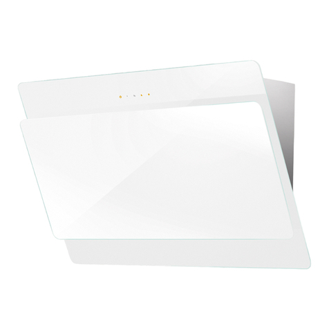
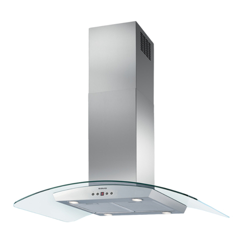
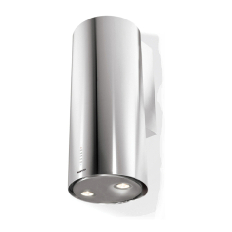
Savo C-7804-S User manual

Instructions Manual
Käyttöohje
C-7804-S
C-7804-W

2
2
INDEX
RECOMMENDATIONS AND SUGGESTIONS.....................................................................................................................3
CHARACTERISTICS.............................................................................................................................................................4
INSTALLATION......................................................................................................................................................................5
USE........................................................................................................................................................................................9
MAINTENANCE...................................................................................................................................................................10
SISÄLTÖ
OHJEET JA SUOSITUKSET...............................................................................................................................................12
MITAT JA OSAT .................................................................................................................................................................. 13
ASENNUS............................................................................................................................................................................14
KÄYTTÖ...............................................................................................................................................................................18
HUOLTO..............................................................................................................................................................................19
EN
FI

EN 3
3
RECOMMENDATIONS AND SUGGESTIONS
The Instructions for Use apply to several versions of this appliance. Accordingly, you may find
descriptionsofindividualfeaturesthatdonotapplytoyourspecificappliance.
INSTALLATION
• The manufacturer will not be held liable for any damages resulting from incorrect or improper
installation.
• The minimum safety distance between the cooker top and the extractor hood is 650 mm (some
models can be installed at a lower height, please refer to the paragraphs on working dimensions
andinstallation).
• Checkthat themainsvoltagecorrespondstothatindicatedontherating platefixedtothe insideof
thehood.
• ForClassIappliances,checkthatthedomesticpowersupplyguaranteesadequateearthing.
Connectthe extractortothe exhaustfluethroughapipeofminimumdiameter120 mm.Theroute
ofthefluemustbeasshortaspossible.
• Donotconnecttheextractorhoodtoexhaustducts carryingcombustionfumes(boilers,fireplaces,
etc.).
• Iftheextractorisusedinconjunctionwithnon-electricalappliances(e.g.gasburningappliances),a
sufficient degree of aeration must be guaranteed in the room in order to prevent the backflow of
exhaust gas.Thekitchenmust havean openingcommunicating directlywiththeopen airin order
to guarantee the entry of clean air. When the cooker hood is used in conjunction with appliances
supplied with energy other than electric, the negative pressure in the room must not exceed 0,04
mbartopreventfumesbeingdrawnbackintotheroombythecookerhood.
• In the event of damage to the power cable, it must be replaced by the manufacturer or by the
technicalservicedepartment,inordertopreventanyrisks.
• Iftheinstructionsforinstallationforthegashob specifyagreaterdistancespecifiedabove,thishas
tobetakenintoaccount.Regulationsconcerningthedischargeofairhavetobefulfilled.
USE
• Theextractorhoodhasbeendesignedexclusivelyfordomesticusetoeliminatekitchensmells.
• Neverusethehoodforpurposesotherthanforwhichithasbeendesigned.
• Neverleavehighnakedflamesunderthehoodwhenitisinoperation.
• Adjust the flame intensity to direct it onto the bottom of the pan only, making sure that it does not
engulfthesides.
• Deepfatfryersmustbecontinuouslymonitoredduringuse:overheatedoilcanburstintoflames.
• Donotflambèundertherangehood;riskoffire
• This appliance is not intended for use by persons (including children) with reduced physical, sen-
soryormental capabilities,orlackof experienceandknowledge, unlessthey havebeengiven su-
pervisionorinstructionconcerninguseoftheappliancebyapersonresponsiblefortheirsafety.
• Childrenshouldbesupervisedtoensurethattheydonotplaywiththeappliance.
• “CAUTION:Accessiblepartsmaybecomehotwhenusedwithcookingappliances.”.
MAINTENANCE
• Switch off or unplug the appliance from the mains supply before carrying out any maintenance
work.
• Cleanand/orreplacetheFiltersafterthespecifiedtimeperiod(Firehazard).
• Cleanthehoodusingadampclothandaneutralliquiddetergent.
Thesymbol onthe product oron itspackagingindicates that thisproduct maynot be treatedas
household waste. Instead it shall be handed over to the applicable collection point for the recycling of
electrical and electronic equipment. By ensuring this product is disposed of correctly, you will help
prevent potential negative consequences for the environment and human health, which could other-
wise be caused by inappropriate waste handling of this product. For more detailed information about
recyclingofthisproduct,pleasecontactyourlocalcityoffice,yourhouseholdwastedisposalserviceor
theshopwhereyoupurchasedtheproduct.
2°

EN 4
4
CHARACTERISTICS
Dimensions
Min.
550mm
Min.
550mm
540
Components
Ref. Q.ty Product components
11 Hood equipped with: Controls, Lights, Filters
31 Hood support equipped with the Exhaust Group
71 tube in PVC
81 Directioned grid
8c 1 Air outlet reduction ø 120mm
91 Reduction flange ø 150-120 mm
10 1 Dumper
Ref. Q.ty Installation components
11 4 Small blocks ø 10
12a 4 Screws 5 x 70
12b 4 Screws M4 x 15
12e 2 Screws 2,9 x 9,5
13 4 Screws plug M4
Q.ty Documentations
1 Instruction booklet
11
12a
3
10
12b
13
1
9
7
12e
88c

EN 5
5
INSTALLATION
Wall drilling and bracket fixing
When installing the hood in recycling version it has to be taken into consideration that space re-
maining between the hood and the upper limit (ceiling or self) is at least 8-10 cm.
On the wall, draw:
•AVertical line up to the ceiling orupper limit, at the centre of the area in which the hood is
to be fitted.
•AHorizontal line at a minimum of 1050 mm above the Cooker Top.
• As indicated, mark a reference point at 100 mm to the right of the vertical reference line.
• Repeat this operation on the other side, checking that the two marks are level.
• As indicated, mark a reference point at 390 mm above the horizontal reference line, and at
100 mm to the right of the vertical reference line.
• Repeat this operation on the other side, checking that the two marks are level.
• Drill at the points marked, using a ø 10 mm drill bit.
• Insert the plugs 11 into the holes.
11
12a
100 100
1050 390
1240
175
170
100 100

EN 6
6
Hood support mounting
• Lean the hood support 3 against the wall making sure that
holes in the hood support correspond to those in the wall.
• Block the hood support to the wall using 4 12a (5 x 70) screws
supplied with the hood.
• Before fastening the screws definitively make sure that the
support is well-levelled. Only after this operation proceed with
the definitive tightening of the screws.
3
12a
Air outlet connection in the ducting version
When installing the hood in ducting version, basing on the in-
staller’s choice, a rigid or a flexible pipe with a ø 150 o 120 mm
is used in order to connect the hood to the air outlet piping. The
pipe connection can be made on the upper part or on the back
side of the hood.
Install the dumper 10.
AIR OUTLET ON THE BACK SIDE OF THE HOOD
• When drilling the air outlet hole in the wall proceed in accord-
ance with the scheme in the paragraph concerning the wall
drilling.
• In case the connection is made with a ø 120 mm pipe insert the
reduction flange 9on the hood body outlet.
• Fix the pipe with an adequate quantity of pipe clamps. This
material is not supplied together with the hood.
• Remove the charcoal filter if present.
AIR OUTLET ON THE UPPER PART OF THE HOOD
• In case the connection of the hood to the air outlet piping is
made with a ø 150 mm pipe then use a rigid or a flexible pipe.
• In case the connection is made with a ø 120 mm pipe insert the
reduction flange 9 on the hood body outlet.
• Fix the air outlet reduction 8c to the air outlet hole of the hood
support with the screws supplied together with the hood.
• Connect the hood to the piping with a rigid or a flexible pipe.
• Fix the pipe with an adequate quantity of pipe clamps. This
material is not supplied together with the hood.
• Remove the charcoal filter if present.
ø 120
9
8c
ø 150
10
10

EN 7
7
RECIRCULATION VERSION AIR OUTLET
• Insert pvc pipe 7 provided onto the Hood Canopy Outlet.
7
ø 150
Hood body mounting
Ducting version
• In case the air outlet connection on the upper part of the hood
has been chosen it will be necessary to remove the pre-cut
piece.
• Lean the hood body on the support and fix it laterally with the
4 12b screws.
• Cover the screw seats with the plugs 13 supplied with the
hood.
Recycling version
• Remove the pre-cut piece.
• Lean the hood body on the support and fix it laterally with the
4 12b screws.
• Cover the screw seats with the plugs 13 supplied with the
hood.
• Place the directioned grid 8on the pipe and make sure that it is
correctly installed.
• Fix the directioned grid 8with the screws 12e supplied togeth-
er with the hood.
• Make sure that the charcoal filters are present.

EN 8
8
ELECTRICAL CONNECTION
• Connect the hood to the mains through a twopole
switch having a contact gap of at least 3 mm.
• Open the lighting unit by pulling on the notch.
• Remove the filters one at a time by pushing them towards the
back of the group and pulling down at the same time.
•Being sure that the connector of the feeding cable is correctly
inserted in the socket placed on the side of the fan.
• Connect the control connector Cmd.
• Connect the Spotlights connector Lux to the socket provided
behind the lighting unit cover.
• Replace the filters, make sure that the handle is visible on the
outside, and the lighting unit.
Cmd
Lux

EN 9
9
L
T1
T2
T3
T4
S1
L
S1
T1 T2 T3 T4
LT3
S1
T2
T1 T4
USE
Control panel
Button Led Function
L- Turns the lights on/off at maximum strength.
T1 Fixed Turns the motor on/off at speed one.
T2 Fixed Turns the Motor on at speed two.
Press and hold the button for approximately 3 seconds, with all the loads turned
off (Motor and Lights), to turn the Activated Charcoal Filter alarm on. The
relevant LED flashes twice to confirm.
To turn the alarm off, press the button again and hold for at least 3 seconds. The
relevant LED flashes once.
T3 Fixed Turns the Motor on at speed three.
Press and hold the button for approximately 3 seconds, with all the loads turned
off (Motor and Lights), to perform a reset of Filter saturation alarm. The LED S1
flashes three times.
T4 Fixed Turns the Motor on at INTENSIVE Speed.
This speed is timed to run for 6 minutes. At the end of this time, the system
returns automatically to the speed that was set before. If it is activated with the
motor turned off, the hood will switch to OFF at the end of the time.
Press and hold for 3 seconds to enable the remote control, indicated by the LED
flashing twice.
Press and hold for 3 seconds to disable the remote control, indicated by the LED
flashing just once.
S1 Fixed Signals the Metal Grease Filter saturation alarm, indicating that it is necessary to
wash the filters. The alarm is triggered after the Hood has been in operation for
100 working hours (Reset see the parag. Maintenance).

EN 1
10
MAINTENANCE
REMOTE CONTROL (OPTIONAL)
The appliance can be controlled using a remote control powered
by a 1.5 V carbon-zinc alkaline batteries of the standard LR03-
AAA type (not included).
• Do not place the remote control near to heat sources.
• Used batteries must be disposed of in the proper manner.
Metal grease filters
These can be washed in the dishwasher, and need to be cleaned
whenever the S1 Led comes on or at least once every 2 months
use, or more frequently if use is particularly intensive.
CLEANING THE FILTERS
Resetting the alarm signal
• Turn the Lights and the Suction Motor off.
• Press T3 and hold for at least 3 seconds, until LED flashes
three times in confirmation.
Cleaning the Filters
• Open the lighting unit by pulling on the nocth.
• Remove the Filter, pushing it towards the back of the unit and
at the same time pulling downward.
• Wash the filter without bending it, and leave it to dry thorough-
ly before replacing (if the surface of the filter changes colour
over time, this will have absolutely no effect on its efficiency).
• Replace, taking care to ensure that the handle faces forwards.
• Replace the lighting unit.

EN 1
11
Activated Charcoal Filter (Recirculation Version)
This cannot be washed or regenerated, and must be changed when led S1 starts to flash, or at
least once every 4 months. The Alarm signal, if it has been activated, only appears when the
Suction motor is turned on.
Activating the alarm signal
• In Recirculation Version Hoods, the Filter Saturation Alarm must be activated on installa-
tion or at a later date.
• Turn the Lights and the Suction Motor off.
• Press button T2 and hold it for 5 seconds until the LED flashes twice in confirmation:
CHANGING
Resetting the alarm signal
• Turn the Lights and the Suction Motor off.
• Press T3 and hold for at least 3 seconds, until LED flashes
three times in confirmation.
Changing the Filter
• Open the lighting unit by pulling on the notch provided.
• Remove the Metal Grease Filter
• Remove the saturated Activated charcoal filter, using the hooks
provided.
• Fit the new Filter, hooking it into place.
• Fit the Grease filter and the Light Unit back into place.
Lighting unit
Warning: This appliance is fitted with a white LED lamp classed
as 1M according to EN 60825-1: 1994 + A1:2002 + A2:2001
standards; maximum optical power emitted @439nm: 7µW. Do
not look directly at the light through optical devices (binoculars,
magnifying glasses…).
•For replacement contact technical support ("To purchase con-
tact technical support").

FI 1
12
OHJEET JA SUOSITUKSET
Nämä käyttöohjeet koskevat useita tuuletintyyppejä. On mahdollista, että teksti käsittelee
yksityiskohtia,jotkaeivätkuuluvalitsemaannetuulettimeen.
ASENNUS
• Valmistajaeivastaavirheellisestätaihuolimattomastaasennuksestaaiheutuvistavahingoista
• Pienin sallittuturvaetäisyysliesitasonja liesikuvun välillä on 650 mm (jotkut mallit voidaan asentaa
alemmas,katsomittojajaasennustakoskeviakappaleita).
• Tarkista, että käytettävän sähköverkon jännite vastaa liesikuvun sisäpuolella olevaan arvokilpeen
merkittyäjännitettä.
• Kytkelaitevainmaadoitettuunpistorasiaan.
• Yhdistä liesituuletin hormiin putkella, jonka halkaisija on vähintään 120 mm. Hormiin menevän
putkenonoltavamahdollisimmanlyhyt.
• Äläyhdistäliesituuletintasavuhormiin(lämmityskattilat,tulisijat,jne.).
• Mikäli liesituuletinta käytetään muiden kuin sähkölaitteiden (esim. kaasuhella) yhteydessä, on
huolehdittava työskentelytilan riittävästä tuuletuksesta, etteivät poistettavat kaasut pääse
virtaamaan takaisin työskentelytilaan. Keittiössä on oltava ilmanvaihtoaukko puhdasta tuloilmaa
varten.Käyttötapahtuuoikeinjavaarattakuntilanenimmäispaineeiylitäarvoa0,04mBar.
• Jos virtajohto vahingoittuu, sen saa vaihtaa vain valmistaja tai tekninen huoltopalvelu, näin
vältetäänkaikkiriskit.
• Jos kaasukäyttöisen keittolaitteen asennusohjeet määräävät, että etäisyyden on oltava yllä
mainittua suurempi, ohjeita on noudatettava. Kaikkia ilmanpoistoa koskevia määräyksiä on
noudatettava.
KÄYTTÖ
• Liesituuletinontarkoitettuvainkotitalouskäyttöön.
• Äläkoskaankäytäliesituuletintamuuhuntarkoitukseenkuin,mihinseonsuunniteltu.
• Äläkoskaanjätäavotultaliesituulettimenalleliesituulettimenollessakäynnissä.
• Säädäliekintehositen,ettäliekkikohdistuuvainastianpohjaaneikäsenreunoille.
• Syviä paistinpannuja on paiston aikana koko ajan pidettävä silmällä, sillä ylikuumentunut öljy voi
leimahtaatuleen.
• Lapsettaihenkilöt,joitaeioleopastettulaitteenoikeaankäyttöön,eivätsaakäyttääliesituuletinta.
• Liesikuvunallaeisaavalmistaaliekitettäviäruokia:tulipalonvaara
• Laitetta eivät saa käyttää henkilöt (lapset mukaan lukien), joiden psyykkinen, aistien tai mielen
terveys on heikentynyt, tai henkilöt, joilla ei ole tarpeellista kokemusta tai taitoa, ellei heidän
turvallisuudestaanvastaavahenkilöolevalmentanutheitälaitteenkäyttööntaivalvositä.
• Valvo,etteivätlapsetpääseleikkimäänlaitteella.
• “HUOMIO: Kosketettavissa olevat osat voivat tulla hyvin kuumiksi jos niitä käytetään
keittolaitteidenkanssa.”
HUOLTO
• Suljelaitetaiirrotasenpistokepistorasiastaennenhoitoa.
• Puhdistaja/taivaihdasuodattimetannetunajankuluttua(Tulipalovaara).
• Puhdistaliesituuletinkosteallakankaallajamiedolla,nestemäiselläpesuaineella.
Symboli , joka on merkitty tuotteeseen tai sen pakkaukseen, osoittaa, että tätä
tuotetta ei saa käsitellä talousjätteenä. Tuote on sen sijaan luovutettava sopivaan sähkö-
ja elektroniikkalaitteiden kierrätyksestä huolehtivaan keräyspisteeseen. Tämän tuotteen
asianmukaisen hävittämisen varmistamisella autetaan estämään sen mahdolliset
ympäristöön ja terveyteen kohdistuvat haittavaikutukset, joita voi aiheutua muussa
tapauksessa tämän tuotteen epäasianmukaisesta jätekäsittelystä. Tarkempia tietoja
tämän tuotteen kierrättämisestä saa paikallisesta kunnantoimistosta,
talousjätehuoltopalvelusta tai liikkeestä, josta tuote on ostettu.
2°

FI 1
13
MITAT JA OSAT
Mitat
Min.
550mm
Min.
550mm
540
Osat
Nro. Määrä Laitteen osa
1 1 Tuuletin (ohjauspaneeli, valaistus, suotimet)
31 Tuulettimen tukiosa (imuyksikkö)
71 PVC-putki
81 Ilmansuuntausritilä
8c 1 Ilmanpoistoputken muhvi (ø 120 mm)
91 Supistuslaippa (ø 150-120 mm)
10 1 Laippa ja venttiili
Nro. Määrä Asennusosat
11 4 Tappi ø 10
12a 4 Ruuvi 5 x 70
12b 4 Ruuvi M4 x 15
12e 2 Ruuvi 2,9 x 9,5
13 4 Ruuvinpäällisnapit M4
Määrä Kirjallinen materiaali
1 Käyttöohjeet
11
12a
3
10
12b
13
1
9
7
12e
88c

FI 1
14
ASENNUS
Seinän poraus
On suositeltavaa, että asennustoimenpiteitä on suorittamassa ainakin kaksi henkilöä, koska
tehtävät ovat monimutkaisia.
Jos liesituuletin asennetaan suodatinversiona, on otettava huomioon, että liesituulettimen
yläpuolelle, ylärajan (katon tai hyllyn) ja laitteen väliin, täytyy jäädä ainakin 8-10 cm tilaa.
Merkitse seinälle:
• Pystysuora viiva kattoon tai ylärajaan saakka liesituulettimen asennusalueen keskikohdalle.
• vaakasuora viiva: vähintään 1050 mm keittotason yläpuolelle.
• Merkitse kuten kuvassa viitepiste 100 mm pystysuorasta viitelinjasta.
• Toista toimenpide toiselle puolelle ja tarkista, että ne ovat samalla tasolla.
• Merkitse viitepiste 390 mm vaakasuoran viitelinjan yläpuolelle ja 100 mm oikealle
pystysuorasta viitelinjasta.
• Toista toimenpide toiselle puolelle.
• Poraa merkittyihin kohtiin reiät ø 10 mm.
• Laita tulpat 11 aukkoihin.
11
12a
100 100
1050 390
1240
175
170
100 100

FI 1
15
Tuulettimen tukiosan asennus
• Aseta tuulettimen tukiosa 3 seinää vasten. Kohdista tukiosan
reiät seinään porattuihin reikiin.
• Kiinnitä tukiosa seinään neljällä mukana tulevalla ruuvilla 12a
(5 x 70).
• Ennen lopullista ruuvien kiristystä vaaita tukiosa. Kiristä
ruuvit.
3
12a
Poistoilmaversiona toimivan tuulettimen liitos
Yhdistä tuuletin ilman ulosmenoaukkoon asentajan valitsemalla
joko jäykällä tai taipuisalla ø 120-150 mm:n putkella.
Putki voidaan johtaa ulos joko tuulettimen ylä- tai takapuolelta.
Sovita laippa (ø 150) 10 tuulettimen ilman ulostuloaukkoon.
LIITOS TUULETTIMEN TAKAA
• Ilman poistoaukkoa tehdessäsi seuraa Seinän poraus
-kappaleen piirrosta.
• Sovita supistusmuhvi 9 tuulettimen ilman ulostuloaukkoon,
mikäli käytät ø120 mm:n putkea.
• Käytä putken kiinnitykseen tarpeellinen määrä putken
kiinnitysosia. Tämä materiaali ei tule tuulettimen mukana.
• Poista mahdolliset aktiivihiilisuotimet.
LIITOS TUULETTIMEN YLÄPUOLELTA
• Mikäli käytät ø 150 mm:n putkea, yhdistä tuuletin ilman
ulosmenoaukkoon joko jäykällä tai taipuisalla putkella.
• Sovita supistusmuhvi 9 tuulettimen ilman ulostuloaukkoon,
mikäli käytät ø120 mm:n putkea.
• Kierrä supistusmuhvi 8c tuulettimen ilman ulostuloaukkoon
mukana tulevilla ruuveilla.
• Yhdistä tuuletin ilman ulosmenoaukkoon joko jäykällä tai
taipuisalla putkella.
• Käytä putken kiinnitykseen tarpeellinen määrä putken
kiinnitysosia. Tämä materiaali ei tule tuulettimen mukana.
• Poista mahdolliset aktiivihiilisuotimet.
ø 120
9
8c
ø 150
10
10

FI 1
16
ILMAN ULOSTULO KIERTOILMAVERSIOSSA
• Asenna mukana tuleva muoviputki 7 tuulettimen ilman
ulostuloaukkoon.
7
ø 150
Tuulettimen asennus
Poistoilmaversio
• Mikäli ilman ulostulo tuulettimesta tapahtuu sen yläpuolelta,
on irrotettava osa ulostuloaukon päältä poistettava ennen
tuulettimen asennusta.
•Aseta tuuletin tukiosaan. Kiinnitä se sivuilta neljällä ruuvilla
12b.
• Aseta mukana tulevat ruuvinpäällisnapit 13 ruuveihin.
Kiertoilmaversio
• Poista irrotettava osa ulostuloaukon päältä .
•Aseta tuuletin tukiosaan. Kiinnitä se sivuilta neljällä ruuvilla
12b.
• Aseta mukana tulevat ruuvinpäällisnapit 13 ruuveihin.
• Aseta ilmansuuntausritilä 8putkeen. Tarkista sen virheetön
asennus.
•Kiinnitä ilmansuuntausritilä 8 mukana tulevilla ruuveilla 12.
• Varmista, että aktiivihiilisuotimet ovat paikoillaan.

FI 1
17
Sähköliitäntä
• Liitä liesituuletin sähköverkkoon asentaen kaksinapainen
kytkin, jonka koskettimien väli on vähintään 3 mm.
• Avaa valaistusryhmä painamalla kiinnitintä.
• Poista suodatin työntämällä sitä ryhmän takaosaan päin ja
vetämällä se alas.
• Varmista, että virtajohdon liitin on oikein kiinnitetty imurin
pistorasiaan.
• Liitä kytkimien liitin Cmd.
• Liitä Lux-valojen liitin valaistusryhmän kannen takana olevaan
pistorasiaan.
• Aseta rasvasuodatin takaisin paikalleen ja sulje valaistusryhmä.
Cmd
Lux

FI 1
18
L
T1
T2
T3
T4
S1
L
S1
T1 T2 T3 T4
LT3
S1
T2
T1 T4
KÄYTTÖ
Käyttöpaneeli
Painike Merkkivalo Toiminto
L - Sytyttää /sammuttaa valon suurimmalla kirkkaudella.
T1 Kiinteä Käynnistää/sammuttaa moottorin ensimmäisellä nopeudella.
T2 Kiinteä Käynnistää moottorin toisella nopeudella.
Jos pidät painiketta painettuna noin 5 sekuntia kun kaikki toiminnot
(moottori ja valo) on sammutettu, aktivoituu aktiivihiilisuodattimen hälytys
ja vastaava merkkivalo vilkkuu kaksi kertaa.
Se poistetaan käytöstä painamalla painiketta uudelleen 5 sekunnin ajan,
vastaava merkkivalo vilkkuu kerran.
T3 Kiinteä Käynnistää moottorin kolmannella nopeudella.
Jos pidät painiketta painettua noin 3 sekuntia kun kaikki toiminnot
(moottori ja valo) on sammutettu, tapahtuu kuittaus ja merkkivalo S1
vilkkuu kolme kertaa.
T4 Kiinteä Käynnistää moottorin TEHONOPEUDELLA.
Nopeus on ajastettu 6 minuutin ajaksi. Kun aika on kulunut järjestelmä
palaa automaattisesti aikaisemmin valitulle nopeudelle. Jos käynnistät
toiminnon moottorin ollessa sammutettu, määrätyn ajan kuluttua laite palaa
tapaan OFF.
Jos pidät painiketta painettuna 5 sekunnin ajan, kaukosäädin aktivoituu ja
sen merkkivalo vilkkuu kaksi kertaa.
Jos pidät painiketta painettuna 5 sekunnin ajan, kaukosäädin poistuu
käytöstä ja sen merkkivalo vilkkuu vain kerran.
S1 Kiinteä Osoittaa metallisten rasvasuodattimien täyttymisen hälytyksen. Suodattimet
täytyy pestä. Hälytys käynnistyy liesituulettimen 100 käyttötunnin jälkeen
(Kuittaus, katso kappaletta Huolto).

FI 1
19
HUOLTO KAUKOSÄÄDIN (LISÄVARUSTE)
Laitetta voidaan ohjata kaukosäätimellä, jossa käytetään 1,5
voltin alkalisia sinkki-hiiliparistoja tyyppiä standardi LR03-
AAA (ei kuulu toimitukseen).
• Älä säilytä kaukosäädintä lämmönlähteiden läheisyydessä.
• Älä jätä paristoja luontoon vaan heitä ne asianmukaiseen
keräysastiaan.
Metalliset rasvasuodattimet
Ne voidaan pestä astianpesukoneessa. Ne täytyy pestä kun
merkkivalo S1 syttyy tai vähintään 2 käyttökuukauden välein tai
useammin, jos niitä käytetään paljon.
SUODATTIMIEN PUHDISTUS
Hälytyksen kuittaus
• Sammuta valo ja imumoottori.
• Paina painiketta T3 ainakin 3 sekunnin ajan, kunnes led
vilkkuu kolme kertaa.
Suodattimien puhdistus
• Avaa valaistusryhmä vetämällä kiinnikettä.
• Poista suodatin työntämällä sitä ryhmän takaosaan päin ja
vetämällä samalla alas.
• Pese suodatin varoen taivuttamasta sitä ja anna sen kuivua
ennen kuin laitat sen paikalleen (suodattimen väri voi ajan
myötä muuttua, mutta se ei vaikuta tehoon).
• Asenna se paikalleen niin että kahva on näkyvissä
ulkopuolella.
• Sulje valaistusryhmä.

FI 2
20
Aktiivihiilihajusuodatin (Suodatinversio)
Suodatinta ei voi pestä eikä uudistaa, se täytyy vaihtaa kun merkkivalo S1 vilkkuu tai
vähintään 4 kuukauden välein. Hälytys tapahtuu vain imumoottorin ollessa toiminnassa, jos
hälytys on aktivoitu.
Hälytyksen aktivoiminen
• Liesituulettimien suodatinversiossa suodattimien täyttymisen hälytys täytyy aktivoida
asennusvaiheessa tai myöhemmin.
• Sammuta valo ja imumoottori.
• Paina painiketta T2 ainakin 5 sekunnin ajan, kunnes led vilkkuu kaksi kertaa.
VAIHTO
Hälytyksen kuittaus
• Sammuta valo ja imumoottori.
• Paina painiketta T3 ainakin 3 sekunnin ajan, kunnes led F
vilkkuu kolme kertaa.
Suodattimen vaihtaminen
• Avaa valaistusryhmä vetämällä kiinnikettä.
• Irrota rasvasuodatin.
• Poista aktiivihiilihajusuodatin irrottamalla se koukuista.
• Asenna uusi suodatin ja kiinnitä se paikalleen.
• Aseta metalliset rasvasuodattimet uudelleen paikoilleen.
• Sulje valaistusryhmä.
Valaistus
Huomio: Tässä laitteessa on valkoinen LED-valo, luokka 1M
vastaa normia EN 60825-1: 1994 + A1:2002 + A2:2001; suurin
valoteho @439nm: 7µW. Älä katso suoraan optisilla välineillä
(kiikari, suurennuslasi….).
• Vaihtoa varten ota yhteys huoltopalveluun ("Hankintaa varten
ota yhteys huoltopalveluun").
Other manuals for C-7804-S
1
This manual suits for next models
1
Table of contents
Languages:
Other Savo Ventilation Hood manuals

Savo
Savo P-2806-W User manual

Savo
Savo G-3305-S User manual

Savo
Savo C-7804-S User manual

Savo
Savo CH-53 User manual

Savo
Savo INCA SMART G-3405-S2 User manual

Savo
Savo R-9709-W User manual

Savo
Savo dRH-9709-W2 User manual

Savo
Savo I-7804-S Instruction Manual

Savo
Savo IH-61 User manual

Savo
Savo R-9709-W User manual
Popular Ventilation Hood manuals by other brands

SmaK
SmaK Neptune 1200 Information & operating instructions

Electrolux
Electrolux CS910CS user manual

Franke
Franke FTU 3807-P WXS 70H Instructions for use and installation

Franke
Franke FNE 605 XS LED Instructions for use and installation

FALMEC
FALMEC FDLUM36I5SS Instruction booklet

Whirlpool
Whirlpool GZ8330XLS0 parts manual