manuals.online logo
Brands
  1. Home
  2. •
  3. Brands
  4. •
  5. Schmalz
  6. •
  7. Industrial Equipment
  8. •
  9. Schmalz FM-SW 120x60 User manual

Schmalz FM-SW 120x60 User manual

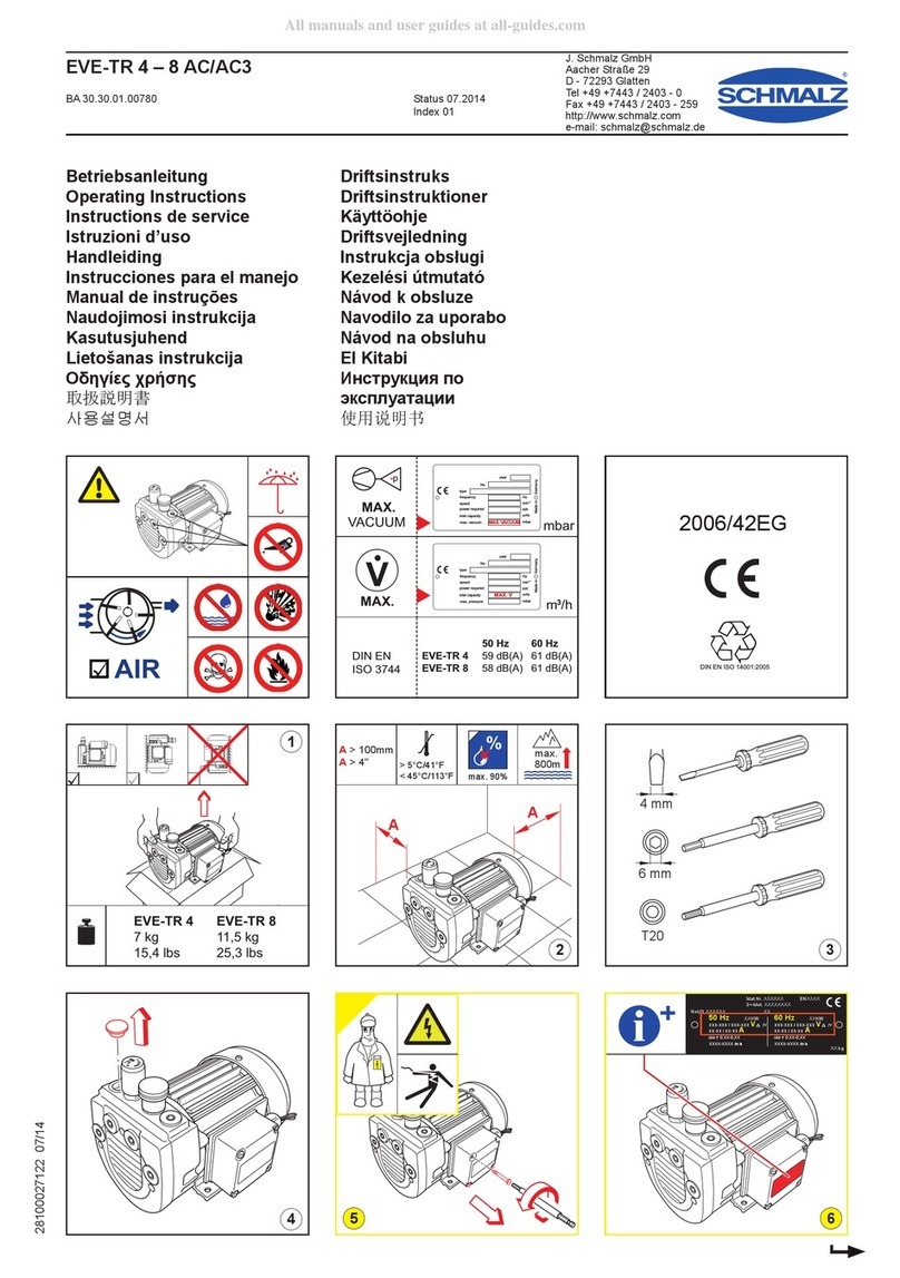
Bedienungsanleitung FM-SW 120x60
Operating Manual FM-SW 120x60
30.30.01.00563 Status 02.2014 / Index 00 Seite / Page 1 / 12
J. Schmalz GmbH
Aacher Straße 29
D - 72293 Glatten
Tel +49 (0) 7443 / 2403 - 0
Fax +49 (0) 7443 / 2403 - 259
www.schmalz.com
schmalz@schmalz.de
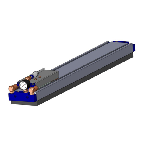
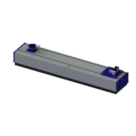
Vakuum-Flächengreifsystem
Area vacuum gripper system
FM-SW 120x60
Betriebsanleitung wurde in deutscher Sprache erstellt.
Für künftige Verwendung aufbewahren!
These operating instructions were written in the German language.
This document should be kept in a safe place for future reference.
Bedienungsanleitung FM-SW 120x60
Operating Manual FM-SW 120x60
30.30.01.00563 Status 02.2014 / Index 00 Seite / Page 2 / 12
J. Schmalz GmbH
Aacher Straße 29
D - 72293 Glatten
Tel +49 (0) 7443 / 2403 - 0
Fax +49 (0) 7443 / 2403 - 259
www.schmalz.com
schmalz@schmalz.de
Inhaltsverzeichnis / Contents
1Sicherheits- und Gefahrenhinweise / Safety Notes
2Installation und Inbetriebnahme / Installation and Commissioning
3Bedienung und Betrieb / Operation
4Wartung / Maintenance
5Fehlersuche / Fault-Finding
6FM-SW 120/60 Basismodul / FM-SW 120/60 basic module
6.1 Montage und Demontage der Saugplatte am FM-SW 120x60 –Basismodul / Mounting and removing the
suction plate on the FM-SW 120x60 basic module
6.2 Montage Dichtmatte / Fitting the sealing mat
7Technische Daten und Abmessungen / Technical data and dimensions
7.1 Technische Daten / Technical data
7.2 Abmessungen Basismodul / Dimensions of the Basic Module
8Zubehör, Optionen / Accessories, Options
8.1 Vakuumschalter / Vacuum switch
9Ersatz- und Verschleißteile / Spare and consumable parts
Bedienungsanleitung FM-SW 120x60
Operating Manual FM-SW 120x60
30.30.01.00563 Status 02.2014 / Index 00 Seite / Page 3 / 12
J. Schmalz GmbH
Aacher Straße 29
D - 72293 Glatten
Tel +49 (0) 7443 / 2403 - 0
Fax +49 (0) 7443 / 2403 - 259
www.schmalz.com
schmalz@schmalz.de
1 Sicherheits- und Gefahrenhinweise / Safety Notes
Allgemeine Hinweise
Durch Druckluft können geschlossene Gefäße explodieren
Durch Vakuum können geschlossene Gefäße implodieren
Der Vakuumerzeuger erzeugt Lärm –evtl. Gehörschutz tragen!
Achtung!
Werden entgegen der bestimmungsgemäßen Verwendung
gefährlicher Staub, Ölnebel, Dämpfe, Aerosole usw. abgesaugt,
gelangen diese in die Abluft was zu Vergiftungen führen kann.
Geeignete und zulässige Vakuumfilter verwenden.
Der Abluftanschluss muss offen sein. Mit geschlossenen
Abluftanschluss steigt der Innendruck im Greifmodul statisch
über den maximal zulässigen Betriebsdruck. Beschädigung des
Greifmoduls und sogar Verletzungsgefahr sind nicht
auszuschließen.
Der integrierte Vakuumerzeuger wurden für einen maximalen
Betriebsdruck von 7 bar (0,7 Mpa, 101 psi) ausgelegt und
dürfen höchstens mit diesem Maximaldruck betrieben werden.
Bei höherem Druck ist Gefahr nicht auszuschließen.
Abluft und eventuell angesaugte Medien und Teile treten mit
hoher Geschwindigkeit aus dem Abluftanschluss aus. Es
besteht dadurch Verletzungsgefahr - vor allem im
Augenbereich! Nicht in den Luftstrom treten oder schauen.
Nur die vorgesehenen Anschlussmöglichkeiten,
Befestigungsbohrungen und Befestigungsmittel verwenden.
General notes
Compressed air can cause closed containers to explode
Vacuum can cause closed containers to implode
The vacuum generator also generates noise - you should
possible wear ear protectors!
Caution!
If the gripper is used in contravention of its intended use and
draws in dangerous dust, oil fog, vapours, aerosols, etc., then
these will be blown out of the exhaust and may cause injuries.
Always use suitable and approved vacuum filters.
At least one of the exhaust-air connections must always be left
open. If both are closed, the pressure within the gripper may
rise above the maximum permissible operating pressure. This
may result in damage to the gripper or even to injuries.
The integrated ejector is designed for a maximum operating
pressure of 7 bar (0.7 Mpa, 101 psi) and may not be operated
at pressures above this value. Higher pressures may endanger
the user.
The exhaust air and any particles which may have been drawn
into the ejector leave the exhaust-air outlet at high velocities.
This may cause injuries, particularly to the eyes. Never stand in
the stream of exhaust air and never look into the exhaust-air
outlet when the ejector is connected to the compressed-air
supply!
Use only the connection facilities, mounting holes and mounting
components provided for this purpose.
Montage / Demontage
Nur im spannungslosen und drucklosen Zustand zulässig!
Die Bauteile dürfen nur von zuverlässigem Fachpersonal
eingesetzt werden, das unter anderem geschult und vertraut ist
mit:
den neuesten geltenden Sicherheitsregeln und
Anforderungen beim Einsatz der Bauteile und deren
Steuerungen in Geräten, Maschinen und Anlagen
(für Magnetventile, Druckschalter, elektronischen
Steuerungen etc.)
und deren erforderlicher elektrischer Ansteuerung, z.B.
Redundanzen und ggf. Rückmeldungen
(für Elektromagnetventile, Druckschalter, elektronischen
Steuerungen etc.).
Assembly and disassembly
This may be done only with the electrical and compressed-air
supplies switched off!
The components may be installed only by reliable and trained
persons who have been instructed in and are familiar with:
the current safety regulations and the requirements for the
use of the components and their controllers in devices,
machines and plants
(applies to solenoid valves, pressure switches, electronic
controllers, etc.);
the necessary electrical controls such as redundancy and, if
applicable, feedback signals
(applies to solenoid valves, pressure switches, electronic
controllers, etc.).
Sicherheitshinweise
Für sichere Installation und störungsfreien Betrieb sind
weiterhin u.a. folgende Verhaltensweisen nebeneinander zu
beachten und einzuhalten:
die Bauteile sind den Verpackungen sorgfältig zu
entnehmen.
Die Bauteile sind generell vor Beschädigungen jeglicher Art
zu schützen
Bei Installation und Wartung: Bauteil, Gerät spannungs- und
Safety notes
For safe installation and trouble-free operation, the following
instructions must be observed and complied with:
Remove the components carefully from their packing
materials.
Handle the components carefully to avoid damaging them.
For installation and maintenance, switch off the electrical
and compressed-air supplies to the component or
Bedienungsanleitung FM-SW 120x60
Operating Manual FM-SW 120x60
30.30.01.00563 Status 02.2014 / Index 00 Seite / Page 4 / 12
J. Schmalz GmbH
Aacher Straße 29
D - 72293 Glatten
Tel +49 (0) 7443 / 2403 - 0
Fax +49 (0) 7443 / 2403 - 259
www.schmalz.com
schmalz@schmalz.de
druckfrei schalten und gegen unbefugtes Wiedereinschalten
sichern.
Es dürfen keine Veränderungen an den Bauteilen
vorgenommen werden.
Sauberkeit im Umfeld und am Einsatzort
Anschlusssymbole und –bezeichnungen befinden sich auf
den Bauteilen und sind entsprechend zu beachten
Nur die vorgesehenen Anschlussmöglichkeiten sind zu
benutzen.
Pneumatische und elektrische Leitungsverbindungen
müssen dauerhaft mit dem Bauteil verbunden und gesichert
sein.
Der Greifer wird in Verbindung mit einem automatisierten
Handlingssystem (Portal / Roboter) eingesetzt. Deshalb
gelten außerdem die Sicherheitsvorschriften des
entsprechenden Systems.
Nichtbeachtung dieser vorgenannten Verhaltensweisen kann zu
Funktionsstörungen, Schäden und Verletzungen –auch
Lebensgefahr- führen.
Die Bauteile sind bei Außerbetriebstellung des Gerätes
umweltgerecht zu entsorgen!
equipment and ensure that they cannot be switched on
inadvertently.
The components may not be modified in any manner.
Keep the components and the work area clean.
The connections are clearly marked on the components and
must be connected accordingly.
Only the connection facilities provided may be used.
Pneumatic pipes/hoses and electric cables must be
permanently connected to the component and secured to
prevent them from becoming loose.
The gripper is used together with an automated handling
system (portal or robot). For this reason, the safety notes for
the handling system must also be observed.
Non-compliance with the above can result in incorrect function,
damage to equipment and (possible fatal) injuries to persons.
Any components removed from the equipment must be
disposed of in accordance with the local environmental
regulations.
2 Installation und Inbetriebnahme / Installation and Commissioning
Befestigung am Handlingsystem:
2 x M6-Schraube und / oder 1 x G1/2“ Schraube bzw.
Federstößel.
Anschluss Vakuumzuleitung:
Verwenden Sie zum Anschluss die vorgesehene 8/6“-
Steckverschraubung. Wir empfehlen, die Vakuumversorgung
mit dem max. möglichen Innendurchmesser zu verlegen. Ein
zu klein gewählter Innendurchmesser bewirkt, dass nicht
genügend Vakuum für optimalen Betrieb zugeführt wird.
Anschluss Druckluft Abblasimpuls:
Wenn für den Abblasimpuls keine Druckluft angelegt wird,
muss der Anschluss mit dem bereits montierten Blindstopfen
verschlossen bleiben, da sonst das erforderliche
Systemvakuum nicht erreicht wird.
Die Druckluft für den Abblasimpuls wird folgendernmaßen
angeschlossen:
Der montierte Blindstopfen wird entfernt und an der
freigelegten G1/8“-Bohrung eine geeignete Verschraubung
montiert. Wir empfehlen die Montage einer 8/6er-
Steckverschraubung in Kombination mit einem 8/6er-PU-
Schlauch.
Anschluss Vakuumschalter:
Zum Anschluss eines optionalen Vakuumschalters wird der
werksseitig montierte Blindstopfen entfernt und über die G1/8“-
Bohrung der Vakuumschalter angeschlossen.
Mounting on the handling system:
2 M6 screws and/or 1 x G1/2“ screw or spring plunger.
Vacuum connection:
Use the prescribed 8/6 adapter for connection of the vacuum.
We recommend using hoses with the maximum possible
internal diameter for the vacuum connection. If the internal
diameter of the hoses is too small, the flow of vacuum will be
too low for optimal operation.
Compressed-air connection for the blow-off pulse:
If no compressed air is connected for the blow-off pulse, the
connection must be sealed with the plug (fitted as standard in
the factory). If this is not done, the necessary system vacuum
will not be achieved.
The compressed air for the blow-off pulse is connected as
follows:
Remove the standard plug from the G1/8“ hole and mount a
suitable adapter. We recommend using an 8/6 adapter and an
8/6 PU hose.
Connecting a vacuum switch:
To connect an optional vacuum switch, remove the plug (fitted
in the factory) from the G1/8“ hole and connect the vacuum
switch in its place.
Bedienungsanleitung FM-SW 120x60
Operating Manual FM-SW 120x60
30.30.01.00563 Status 02.2014 / Index 00 Seite / Page 5 / 12
J. Schmalz GmbH
Aacher Straße 29
D - 72293 Glatten
Tel +49 (0) 7443 / 2403 - 0
Fax +49 (0) 7443 / 2403 - 259
www.schmalz.com
schmalz@schmalz.de
3 Bedienung und Betrieb / Operation
Achtung:
Im Transportbereich der Nutzlast, die mit dem FM-SW 120x60
bewegt wird, dürfen sich keine Personen unter der Nutzlast
aufhalten. Bei Ausfall / Abfall der Druckluftversorgung löst sich
die Last.
Weitere Angaben unter „Sicherheits- und Gefahrenhinweise“.
Caution:
Persons must be kept clear of the area over which loads are
moved with the FM-SW 120x60. However, failure of the
compressed air supply, or a pressure drop, will cause the load
to be dropped.
See "Safety Notes" for further details.
4 Wartung / Maintenance
Bei äußerer Verschmutzung mit Lappen und Seifenlauge (max.
60° C) reinigen. Darauf achten, dass der Schalldämpfer nicht
mit Seifenlauge getränkt wird.
Weitere Wartungsarbeiten sind in der Regel nicht erforderlich.
Bei starker Verschmutzung kann es zu Betriebsstörungen
kommen, wir empfehlen dann eine Überholung im Werk.
Für die Saugmatten sind Austauschmatten erhältlich.
If the outside of the unit becomes dirty, clean it with a cloth and
soapy water (maximum temperature. 60° C). Take care not to
soak the silencer with the soapy water.
Further maintenance is generally unnecessary. If the unit
becomes very dirty, it may malfunction. In such cases, we
recommend that you have it overhauled in the factory.
Replacement mats are available for the suction mats.
5 Fehlersuche / Fault-Finding
Störung
mögliche
Ursache
Abhilfe
Symptom
Possible cause
Remedy
Vakuumniveau
wird nicht
erreicht oder
Vakuum wird
zu langsam
aufgebaut
Leckage in
Vakuumschlauch-
leitung
Schlauchverbindungen
überprüfen
Vacuum to low
or vacuum
generation
takes too long
Leak in vacuum
hose
Check hose connectors
Leckage am
Sauggreifer
Sauggreifer und
Dichtungseinsatz
überprüfen
Leaks on suction
pad
Check suction pads and
gasket
Innen-der
Vakuumschlauch-
leitungen zu klein
Schlauchleitungen mit
größerem Innen-
verwenden
Internal diameter
of vacuum hose to
small
Use hoses with a larger
internal diameter.
Fehlende
Blindstopfen
Blindstopfen
einschrauben und
abdichten
Sealing plug
missing
Screw in and tighten the
sealing plug
Abblasimpuls
falsch
angeschlossen
Abluftanschluss gegen
Atmosphäre prüfen
Blow-off pulse
connected
incorrectly
Test the blow-off
connection with respect to
atmospheric pressure
Nutzlast kann
nicht
festgehalten
werden
Vakuumniveau zu
gering
Mögliche Ursachen
siehe oben
Load cannot
be held
Vacuum too low
See above
Saugkraft für
Nutzlast
ungeeignet
Zusätzliches FM-SW
120x60-Modul
anschließen
Suction force not
suitable for the
load
Install an additional FM-
SW 120x60 gripper
Bedienungsanleitung FM-SW 120x60
Operating Manual FM-SW 120x60
30.30.01.00563 Status 02.2014 / Index 00 Seite / Page 6 / 12
J. Schmalz GmbH
Aacher Straße 29
D - 72293 Glatten
Tel +49 (0) 7443 / 2403 - 0
Fax +49 (0) 7443 / 2403 - 259
www.schmalz.com
schmalz@schmalz.de
6 FM-SW 120/60 Basismodul /
FM-SW 120/60 basic module
Pos
Bezeichnung / Designation
1
Verschlussschraube (Vakuumschalter-/Abblasbohrung) / Screw plug (vacuum switch/blow-off hole)
2
Vakuumanschluss (8/6) / Vacuum connection (8/6)
3
Arretierstift / Locking pin
4
Grundkörper Kunststoff / Body, plastic
5
Befestigungsbohrungen M6 / Mounting holes M6
6
Befestigungsbohrung G1/2“ / Mounting hole G1/2“
7
Trägerplatte / Base plate
8
Dichtungseinsatz / Gasket
Bedienungsanleitung FM-SW 120x60
Operating Manual FM-SW 120x60
30.30.01.00563 Status 02.2014 / Index 00 Seite / Page 7 / 12
J. Schmalz GmbH
Aacher Straße 29
D - 72293 Glatten
Tel +49 (0) 7443 / 2403 - 0
Fax +49 (0) 7443 / 2403 - 259
www.schmalz.com
schmalz@schmalz.de
6.1 Montage und Demontage der Saugplatte am FM-SW 120x60 –Basismodul /
Mounting and removing the suction plate on the FM-SW 120x60 basic module
Montage/ Demontage:
Die Saugplatte [2] wird von unten auf das Basismodul [1]
aufgesteckt, bis die beiden Laschen der Saugplatte in die
seitlichen Arretierstifte [3] des Basismoduls einrasten.
Darauf achten, dass der Dichtungseinsatz sauber anliegt!
Zur Demontage der Saugplatte einen ausreichend großen
Schraubendreher verwenden, der von oben in die seitlichen
Aussparungen [4] des Basismoduls eingesetzt wird. Durch
leichtes Verdrehen können die Laschen der Saugplatte über
die seitlichen Arretierstifte des Basismoduls gehoben werden
und die Saugplatte kann demontiert werden.
Mounting / Removing:
The suction plate [2] is pushed onto the bottom of the basic
module [1] so that the two side plates of the suction plate
engage with the locking pins [3] on the side of the basic
module. Take care that the gasket is in good contact with the
suction plate.
To remove the suction plate, insert a sufficiently large
screwdriver into the recess [4] on the side of the basic module
and turn it to lift the side plate of the suction plate over the
locking pin of the basic module. Repeat on the other side and
pull off the suction plate.
6.2 Montage Dichtmatte / Fitting the sealing mat
Ablösen alte Dichtmatte
Dichtmatte [5] abziehen (evtl. mit Fön erwärmen).
Klebereste entfernen (z.B. mit Aceton).
Montage neue Dichtmatte
Schutzpapier entfernen. Dichtmatte [5] fest und vollflächig
auf Saugplatte [2] aufdrücken. Öffnungen in der Dichtmatte
und Bohrungen im Blech müssen fluchten!
Removing the old sealing mat
Pull off the old mat [5] (heating it, if necessary, with hot air).
Remove residues of adhesive (e.g. with acetone).
Fitting the new sealing mat
Remove the protective paper. Press the sealing mat [5]
against the suction plate [2], applying firm pressure over its
entire area. Make sure that the holes in the mat are aligned
with the holes in the plate!
Bedienungsanleitung FM-SW 120x60
Operating Manual FM-SW 120x60
30.30.01.00563 Status 02.2014 / Index 00 Seite / Page 8 / 12
J. Schmalz GmbH
Aacher Straße 29
D - 72293 Glatten
Tel +49 (0) 7443 / 2403 - 0
Fax +49 (0) 7443 / 2403 - 259
www.schmalz.com
schmalz@schmalz.de
7 Technische Daten und Abmessungen / Technical data and dimensions
7.1 Technische Daten / Technical data
Medium druckluftseitig:
gefilterte ( max. 40 µm) und geölte oder nicht geölte Druckluft
oder neutrale Gase gemäss EN 983
Medium vakuumseitig:
trockene und nicht aggressive Gase
zulässiger Betriebsdruck:
5 ... 6 bar
Zul. Temperaturbereich:
Umgebung: 0 °C ... +50 °C
zu evakuierendes Medium: 0 °C ... +50 °C
Bei vertikalem Greifen beträgt die maximal zulässige
Einsatztemperatur (Umgebungstemperatur und
Oberflächentemperatur des zu greifenden Werkstücks) +36°C.
Eigengewicht:
Kunststoffausführung: 0,5 kg
Medium on pressure side:
filtered (max. 40 µm) and dry or lubricated compressed air or
neutral gas in accordance with EN 983
Medium on vacuum side:
dry, non-aggressive gas
Permissible operating pressure:
5 ... 6 bar
Permissible temperature ranges:
Environment: 0 °C ... +50 °C
Medium to be evacuated: 0 °C ... +50 °C
The maximum permitted temperature (ambient temperature
and surface temperature of the workpiece that is to be
gripped) for use with vertical grippers is +36 C.
Weight:
Plastic version: 0.5 kg
Art.-Nr. /
Art.-No.
Anschluss Vakuum /
Vacuum connection
Betriebsdruck Greifmodul /
Operationg pressure, gripper
Max. Vakuum /
Max. vacuum [%]
Anzahl Saugzellen /
Suction cells
10.01.11.01823
8 / 6 mm
5-6 bar
80
10
Bedienungsanleitung FM-SW 120x60
Operating Manual FM-SW 120x60
30.30.01.00563 Status 02.2014 / Index 00 Seite / Page 9 / 12
J. Schmalz GmbH
Aacher Straße 29
D - 72293 Glatten
Tel +49 (0) 7443 / 2403 - 0
Fax +49 (0) 7443 / 2403 - 259
www.schmalz.com
schmalz@schmalz.de
7.2 Abmessungen Basismodul / Dimensions of the Basic Module
Funktionsmaße der Basismodule, Darstellung mit Saugplatte /
Functional dimensions of basic module (shown with suction plate)
Stirnsenkung /
screw sinking
Bedienungsanleitung FM-SW 120x60
Operating Manual FM-SW 120x60
30.30.01.00563 Status 02.2014 / Index 00 Seite / Page 10 / 12
J. Schmalz GmbH
Aacher Straße 29
D - 72293 Glatten
Tel +49 (0) 7443 / 2403 - 0
Fax +49 (0) 7443 / 2403 - 259
www.schmalz.com
schmalz@schmalz.de
8 Zubehör, Optionen / Accessories, Options
8.1 Vakuumschalter / Vacuum switch
Es können folgende Vakuumschalter nachgerüstet werden:
The System can be retrofitted with the following vacuum switches:
Bezeichnung
Designation
Art.-Nr.
Vakuumschalter VS-V-D-NPN
Vacuum switch VS-V-D-NPN
10.06.02.00049
Vakuumschalter VS-V-D-PNP
Vacuum switch VS-V-D-PNP
10.06.02.00055
Vakuumschalter VS-V-A-NPN
Vacuum switch VS-V-A-NPN
10.06.02.00028
Vakuumschalter VS-V-A-PNP
Vacuum switch VS-V-A-PNP
10.06.02.00038
Nähere Infos siehe Katalog oder Anhang / For more information see catalogue or appendix
Einbau Vakuumschalter / Installing the vacuum switch
1. Einen der beiden Blindstopfen entfernen.
2. Vakuumschalter von oben konzentrisch zur freigelegten
G 1/8“-Bohrung ausrichten.
3. Vakuumschalter vakuumdicht in G 1/8“-Bohrung
eindrehen.
1. Remove one of the plugs.
2. Align the vacuum switch with the G 1/8“ hole from which
the plug was removed.
3. Screw the vacuum switch into the G 1/8“ hole and tighten
it.
Bedienungsanleitung FM-SW 120x60
Operating Manual FM-SW 120x60
30.30.01.00563 Status 02.2014 / Index 00 Seite / Page 11 / 12
J. Schmalz GmbH
Aacher Straße 29
D - 72293 Glatten
Tel +49 (0) 7443 / 2403 - 0
Fax +49 (0) 7443 / 2403 - 259
www.schmalz.com
schmalz@schmalz.de
9 Ersatz- und Verschleißteile / Spare and consumable parts
Für dieses Gerät übernehmen wir eine Gewährleistung gemäß unseren Allgemeinen Verkaufs- und Lieferbedingungen.
Das gleiche gilt für Ersatzteile, sofern es sich um von uns gelieferte Originalteile handelt. Für Schäden, die durch die
Verwendung von anderen als Originalersatzteilen oder Originalzubehör entstehen, ist jegliche Haftung unsererseits
ausgeschlossen. Ausgenommen von der Gewährleistung sind alle Verschleißteile.
This equipment is guaranteed in accordance with our General Conditions of Business. This also applies to spare parts where
these are original parts supplied by us. We will assume no liability for damage caused by the use of non-original spare parts and
accessories. Wear and consumable parts are not covered by the guarantee.
Saugplatte / Suction plate
Dichtplatte / Sealing mat
Bezeichnung
Designation
Art.-Nr.
Legende
Saugplatte FM-SW 120x60
Suction plate FM-SW 120x60
10.01.10.03090
VB
Dichtplatte
Sealing mat
10.01.10.00874
V
Einzelpositionen / Individual components
Pos
Bezeichnung
Designation
Art.-Nr.
Legende
1
8/6er-Winkelverschraubung
8/6 elbow adapter
10.08.02.00160
E
2
G1/8“-Blindstopfen
G 1/8" plug
10.08.06.00043
E
E=Ersatzteil, VB= Verschleißteilbaugruppe, enthält Verschleißteile
E= Spare part, VB= Consumable-part assembly, contains consumable parts
Technische Änderungen, Druckfehler und Irrtümer
vorbehalten!
We reserve the right to make technical changes. No
responsibility is taken for printing or other types of errors.
1
2
Bedienungsanleitung FM-SW 120x60
Operating Manual FM-SW 120x60
30.30.01.00563 Status 02.2014 / Index 00 Seite / Page 12 / 12
J. Schmalz GmbH
Aacher Straße 29
D - 72293 Glatten
Tel +49 (0) 7443 / 2403 - 0
Fax +49 (0) 7443 / 2403 - 259
www.schmalz.com
schmalz@schmalz.de

Other Schmalz Industrial Equipment manuals

Schmalz VCBL-G-K1 User manual

Schmalz

Schmalz VCBL-G-K1 User manual

Schmalz 10.01.38.06443 User manual

Schmalz

Schmalz 10.01.38.06443 User manual

Schmalz FXP User manual

Schmalz

Schmalz FXP User manual

Schmalz SSP User manual

Schmalz

Schmalz SSP User manual

Schmalz SCPSb-2 User manual

Schmalz

Schmalz SCPSb-2 User manual

Schmalz SEAC 10 RP Series User manual

Schmalz

Schmalz SEAC 10 RP Series User manual

Schmalz VCMC-S4 QUICK User manual

Schmalz

Schmalz VCMC-S4 QUICK User manual

Schmalz SBPG User manual

Schmalz

Schmalz SBPG User manual

Schmalz CobotPump ECBPi User manual

Schmalz

Schmalz CobotPump ECBPi User manual

Schmalz ROB-SET ECBPi MATCH UR User manual

Schmalz

Schmalz ROB-SET ECBPi MATCH UR User manual

Schmalz FMP-SVK Series User manual

Schmalz

Schmalz FMP-SVK Series User manual

Schmalz Mini Compact Ejector SCPMc User manual

Schmalz

Schmalz Mini Compact Ejector SCPMc User manual

Schmalz FXP-S-SVK User manual

Schmalz

Schmalz FXP-S-SVK User manual

Schmalz SCPSi-UHV-HD User manual

Schmalz

Schmalz SCPSi-UHV-HD User manual

Schmalz SPZ User manual

Schmalz

Schmalz SPZ User manual

Schmalz SEAC 10 ECO User manual

Schmalz

Schmalz SEAC 10 ECO User manual

Schmalz Compact Ejector SCPMc User manual

Schmalz

Schmalz Compact Ejector SCPMc User manual

Schmalz SNG-M Series Operating instructions

Schmalz

Schmalz SNG-M Series Operating instructions

Schmalz SPZ User manual

Schmalz

Schmalz SPZ User manual

Schmalz FXCB User manual

Schmalz

Schmalz FXCB User manual

Schmalz FMP-SVK Series User manual

Schmalz

Schmalz FMP-SVK Series User manual

Schmalz SBSm 14 90-3 S1 User manual

Schmalz

Schmalz SBSm 14 90-3 S1 User manual

Schmalz SNG-R V Series User manual

Schmalz

Schmalz SNG-R V Series User manual

Schmalz SPZ 10.01.22.02100 User manual

Schmalz

Schmalz SPZ 10.01.22.02100 User manual

Popular Industrial Equipment manuals by other brands

Peri 019200 Instructions for use

Peri

Peri 019200 Instructions for use

PushCorp AFD92 manual

PushCorp

PushCorp AFD92 manual

SEI Industries BAMBI BUCKET 2020A Operation manual

SEI Industries

SEI Industries BAMBI BUCKET 2020A Operation manual

Sumitomo Drive Technologies PARAMAX SFC Series quick start guide

Sumitomo Drive Technologies

Sumitomo Drive Technologies PARAMAX SFC Series quick start guide

cytiva ÄKTA go operating instructions

cytiva

cytiva ÄKTA go operating instructions

Graco Reactor H-25 Series Operation

Graco

Graco Reactor H-25 Series Operation

Spartan Equipment Angle Broom Owner's/operator's manual

Spartan Equipment

Spartan Equipment Angle Broom Owner's/operator's manual

CNC QB2 user guide

CNC

CNC QB2 user guide

Flowserve Limitorque HBC Series User instructions

Flowserve

Flowserve Limitorque HBC Series User instructions

Festo HGDS Series operating instructions

Festo

Festo HGDS Series operating instructions

ABB HT612770 Operation manual

ABB

ABB HT612770 Operation manual

ABB HT566023 Operation manual

ABB

ABB HT566023 Operation manual

Baileigh Industrial BB-9616M-V2 Operator's manual

Baileigh Industrial

Baileigh Industrial BB-9616M-V2 Operator's manual

Siemens SIMATIC S7-1500R/H Equipment manual

Siemens

Siemens SIMATIC S7-1500R/H Equipment manual

ABB TPS52 Series Operation manual

ABB

ABB TPS52 Series Operation manual

goodnature AA-375R owner's manual

goodnature

goodnature AA-375R owner's manual

Kenpro SQUEEZE KEY KP-100 instruction manual

Kenpro

Kenpro SQUEEZE KEY KP-100 instruction manual

ABB Power2 850-M Operation manual

ABB

ABB Power2 850-M Operation manual

manuals.online logo
manuals.online logoBrands
  • About & Mission
  • Contact us
  • Privacy Policy
  • Terms and Conditions

Copyright 2025 Manuals.Online. All Rights Reserved.