manuals.online logo
Brands
  1. Home
  2. •
  3. Brands
  4. •
  5. Schmalz
  6. •
  7. Industrial Equipment
  8. •
  9. Schmalz SCPSi - 2 NO - M12-5 Series Technical specifications

Schmalz SCPSi - 2 NO - M12-5 Series Technical specifications

SCPSi series
SCPSi –2 - xx –xx –NO –M12-5
SCPSi –2 - xx –xx –NC –M12-5
DE Kurz-Bedienungsanleitung 2
EN Brief operating instructions 2
FR Notice d’utilisation simplifiée 2
ES Manual de instrucciones resumido 7
IT Manuale d’uso breve 7
NL Beknopte bedieningsinstructies 7
J. Schmalz GmbH · Johannes-Schmalz-Str. 1 · D-72293 Glatten · T: +49 7443 2403-0
[email protected]
30.30.01.00660 · 00 · 07/14
2 | DE/EN/FR/ES/IT/NL © J. Schmalz GmbH · 30.30.01.00660 · 00 · 07/2014
DE Kurz-Bedienungsanleitung
EN Brief operating instructions
FR Notice d’utilisation simplifiée
Hinweis: Diese Kurzanleitung beschreibt die grundlegenden Funktionen des Ejektors und dient erfahrenen
Anwendern als Schnelleinstieg. Weiterführende und vollständige Funktionsbeschreibungen des Ejektors sind der
ausführlichen Betriebsanleitung zu entnehmen.
Siehe: www.schmalz.com
Note: These brief operating instructions describe the basic functions of the ejector. They are intended to provide a
quick start for experienced users. Consult the detailed operating instructions for a more in-depth and complete
description of the ejector’s functions.
See: www.schmalz.com
Remarque: Cette notice décrit les fonctions de base de l’éjecteur et sert de présentation rapide aux utilisateurs
expérimentés. Pour tout complément d’information et la description complète du fonctionnement de l'éjecteur,
veuillez consulter la version complète des instructions de service.
Voir: www.schmalz.com
3 | DE/EN/FR/ES/IT/NL © J. Schmalz GmbH · 30.30.01.00660 · 00 · 07/2014
1Sicherheitshinweise / Security Note / Remarque sur la
sécurité
Vor Inbetriebnahme des Ejektors sind
grundsätzlich die Sicherheitshinweise
der ausführlichen Betriebsanleitung zu
beachten.
Es wird ausdrücklich darauf
hingewiesen, dass diese Kurzanleitung
keinen Anspruch auf Vollständigkeit
erhebt.
You must observe the safety
instructions found in the detailed
operating instructions before
starting to operate the ejector.
We particularly emphasize that
these brief operating instructions
make no claim to being exhaustive.
Veuillez impérativement respecter
les consignes de sécurité
contenues dans les instructions de
service détaillées avant de mettre
l'éjecteur en service.
Nous attirons votre attention sur le
fait que cette notice d’utilisation
n’est pas exhaustive.
Der Betrieb des Ejektors ist
ausschließlich über Netzgeräte mit
Schutzkleinspannung (PELV) gestattet.
Es ist für sichere elektrische Trennung
der Versorgungsspannung gemäß
EN60204 zu sorgen.
The ejector may only be operated
via power supply units with
protected extra-low voltage (PELV).
The system must incorporate safe
electrical cut-off of the power
supply in compliance with
EN60204.
Le fonctionnement de l'éjecteur
est autorisé exclusivement via des
blocs secteur avec très basse
tension de protection (PELV).
Garantissez une séparation
électrique efficace de la tension
d’alimentation conformément à EN
60204.
2Geräteaufbau / Configuration / Configuration
1
Anzeige Prozesszustand
Process state display
Affichage de l'état du processus
2
Bedienelemente
Control elements
Élément de commande
3
Drosselschraube Abblasen
Throttle screw Blow-Off
Throttle vis de purge
4
Vakuumanschluss G1/8“
Vacuum connector G1/8“
Raccord de vide G1/8“
5
Elektrischer Anschluss M12-5
Electrical connection M12-5
Connexion électrique M12-5
6
Steuerung
Control unit
Boît de commande
7
Befestigungsbohrungen für M4
Mounting hole for M4
Trou de fixation pour M4
8
Druckluftanschluss G1/8“
Compressed air connection G1/8“
Raccord d'air comprimé G1/8“
9
Schalldämpferdeckel
Cover of the silencer
Couverture du silencieux
10
Abluftausgang
Exhaust outlet
Sortie d'échappement
3
4
1 5
6
8
7
9
(max. 4Nm)
(max. 4Nm)
10
2
10
(max. 2Nm)
4 | DE/EN/FR/ES/IT/NL © J. Schmalz GmbH · 30.30.01.00660 · 00 · 07/2014
3Grundeinstellung / Basic Setting / Réglages de base
H-1 / h-1
Einstellung der Schaltschwelle der
Luftsparfunktion
Setting the switching threshold of the
air saving function
Définir le seuil de commutation de
la fonction d'économie d'air
H-2 / h-2
Einstellung der Schaltschwelle der
Teilekontrolle
Setting the switching threshold of the
part control
Définir le seuil de commutation de
la contrôle part
tbl
Einstellung der Abblaszeit
Setting the Blow-Off-time
Définir le temp de soufflage
CAL
Nullpunkteinstellung für
Vakuumsensor
Zero point setting vacuum-sensor
Réglage du point zéro capteur de
vide
weiter zu h-1
Continue to h-1
Suivant pour h-1
Einstellung
des Wertes
Setting the
value
Réglage de
la valeur
Wert blinkt zur
Bestätigung
Value flashes
to confirm
Clignotement
de la valeur pr.
confirmation
blinken
flashing
clignotement
> 2 sec.
> 2 sec.
> 2 sec.
blinken
flashing
clignotement
5 | DE/EN/FR/ES/IT/NL © J. Schmalz GmbH · 30.30.01.00660 · 00 · 07/2014
4Elektrischer Anschluss / Electrical connection /
Branchement électrique
SIO
IO-Link
SCPSi –xx –xx –xx –M12-5
US/A (24VDC)
BN
1
M12
1
BN
US/A (24VDC)
Saugen / Suction / Aspiration
WH
2
2
WH
-
GndSA
BU
3
3
BU
GndS/A
H2
BK
4
4
BK
C/Q (IO Link)
Abblasen / Blow-off / Soufflag
GY
5
5
GY
-
5Betriebsparameter / Operating parameters /
Paramètres d’exploitation
Betriebsparameter elektrisch / Operating parameters electrically /
Paramètres de fonctionnement électriquement
min
typ
max
Versorgungsspannung
Supply voltage
Tension d‘alimentation
US/A
19,2
24
26,4
VDC
Nennstrom (US/A)
Nominal current (US/A)
Courant nominal (US/A)
SCPSi –xx –NO
IS/A
-
120
-
mA
SCPSi –xx –NC
IS/A
-
70
-
mA
Ausgangsstrom (PNP)
Output current (PNP)
Courant de sortie (PNP)
IO
-
-
150
mA
Ausgangsstrom (NPN)
Output current (NPN)
Courant de sortie (NPN)
IO
-
-
100
mA
Betriebsparameter pneumatisch / Operating parameters pneumatically /
Paramètres de fonctionnement pneumatiquement
Betriebsdruck
Operating pressure
Pression de fonction
p
2
4
6
bar
Luftverbrauch
Air consumption
Consommation d‘air
SCPSi 2-07
Q
24
l/min
SCPSi 2-09
Q
37
l/min
SCPSi 2-14
Q
87
l/min
US/ UA
BUS I/O
US/ UA
BUS IO-Link
6 | DE/EN/FR/ES/IT/NL © J. Schmalz GmbH · 30.30.01.00660 · 00 · 07/2014
IO-Link Kommunikation / Communication / Communication
SIO-Mode
SIO-Mode
SIO-Mode
Yes
Frame-Typ
Frame-Type
Frame-Typ
2_V
Baudrate
Baud rate
Débit en bauds
38,4 kBd
Minimale Zykluszeit
Minimum cycle time
Temps de cycle minimum
3,3 ms
Prozessdaten input / output
Processdata input / output
Traiter les données input / output
4 byte / 2 byte
IO-Link Prozessdaten / Process Data / Données de process
Bit
PD-In Byte 0
0
H2 (Teilekontrolle)
H2 (Part Control)
H2 (Contrôle part)
1
H1 (Regelung)
H1 (Control)
H1 (Contrôle)
5
Systemstatus grün
System status green
L'état du système: vert
6
Systemstatus gelb
System status yellow
L'état du système: jaune
7
Systemstatus rot
System status red
L'état du système: rouge
PD-Out Byte 0
0
Saugen EIN/AUS
Suction On / OFF
Aspiration ON / OFF
1
Abblasen EIN/AUS
Blow-off ON / OFF
Soufflage ON / OFF
2
Einrichtbetrieb EIN/AUS
Set-Up mode ON / OFF
Mode de configuration ON / OFF
6
Produktions-Setup-Profil, Bit 0
Production profile setup, Bit 0
Config du profil de product, Bit 0
7
Produktions-Setup-Profil, Bit 1
Production profile setup, Bit 1
Config du profil de product, Bit 1

Alle Prozessdaten siehe
ausführliche Betriebsanleitung
All Process data see detailed
operating instructions
Toutes les données de process voir
les instructions d‘utilisation
IO-Link Parameter (teilweise) / Parameters (partial) / Paramètre (partielle)
64
2
Systemvakuum
System vacuum
Vide du système
130
1
Fehler-Code
Error Code
Code d‘erreur
146
1
Warnungs-Code
Warning Code
Code d'avertissement
68
1
Luftsparfunktion
Air saving function
Fonction d'économie d'air
78
1
Deaktivierung Dauersaugen
Disable continous sucking
Désactiver continue de sucer
100
2
Schaltpunkt H1
Switchingpoint H1
Point de commutation H1
101
2
Hysterese h1
Hysteresis h1
Hystérésis h1
102
2
Schaltpunkt H2
Switchingpoint H2
Point de commutation H2
103
2
Hysterese h2
Hysteresis h2
Hystérésis h2
106
2
Abblaszeit
Blow-off time
Temps de soufflage
107
2
Zulässige Evakuierungszeit
Permissible evacuation time
Temps d'évacuation permis
108
1
Zulässiger Leckagewert
Permissible leakage value
Valeur de fuite admissible
69
1
Abblasfunktion
Blow-off mode
Fonction de purge
71
1
Funktion OUT2
OUT2 function
OUT2 fonction
73
1
Signaltyp
Signal type
Type de signal
74
1
Vakuumeinheit
Vacuum display unit
Présentoir vide
75
1
Ausschaltverzögerung
Switch-off delay
Délai de mise hors circuit
79
1
Displaydrehung
Display rotation
Rotation d‘affichage
76
1
Eco-Modus
Eco-Mode
Eco-Mode
77
2
PIN-Code
PIN-code
PIN-Code

Alle Parameter siehe
ausführliche Betriebsanleitung
All Parameters see detailed
operating instructions
Tous les paramètres voir les
instructions d‘utilisation
7 | DE/EN/FR/ES/IT/NL © J. Schmalz GmbH · 30.30.01.00660 · 00 · 07/2014
ES Manual de instrucciones resumido
IT Manuale d’uso breve
NL Beknopte bedieningsinstructies
Nota: Estas instrucciones resumidas describen las funciones básicas del eyector y sirven de acceso rápido para el
usuario experimentado. Las descripciones completas de las funciones del eyector se deben consultar en las
instrucciones de servicio completas.
Véase: www.schmalz.com
Nota: Questa guida breve descrive le funzioni principali dell’eiettore ed è prevista per una rapida introduzione per gli
utenti esperti. Una descrizione più dettagliata e completa del funzionamento dell’eiettore è riportata nella versione
integrale delle Istruzioni per l’uso.
Vedi: www.schmalz.com
NL: Aanwijzing: Deze korte handleiding beschrijft de wezenlijke functies van de ejector en is bedoeld voor ervaren
gebruikers teneinde snel aan de slag te kunnen. Verdergaande en volledige beschrijvingen van de werking van de
ejector zijn in de uitvoerige bedieningsinstructies te vinden.
Zie: www.schmalz.com
8 | DE/EN/FR/ES/IT/NL © J. Schmalz GmbH · 30.30.01.00660 · 00 · 07/2014
1Indicaciones de seguridad / Indicazioni di sicurezza /
Veiligheidsinstructies
Antes de poner en marcha el
eyector, es imprescindible
observar las normas de seguridad
de las instrucciones de manejo
completas.
Advertimos explícitamente que
estas instrucciones resumidas no
pretenden ser completas.
Prima della messa in funzione
dell’eiettore, leggere attentamente
le indicazioni di sicurezza riportate
nella versione integrale delle
Istruzioni per l’uso.
Si fa notare espressamente che
questa guida breve non ha alcun
intento di completezza.
Vóór de inbedrijfstelling van de ejector
dienen principieel de
veiligheidsinstructies zoals die zijn
vermeld binnen de uitvoerige
bedieningsinstructies in acht te worden
genomen.
Wij wijzen er met nadruk op dat er
voor wat deze korte handleiding
betreft geen aanspraak op volledigheid
kan worden gemaakt.
El eyector se debe operar sólo con
fuentes de alimentación con baja
tensión de protección (PELV). Se
debe procurar una desconexión
eléctrica segura de la tensión de
alimentación según EN60204.
Il funzionamento dell'eiettore è
ammesso esclusivamente mediante
alimentatori di rete con bassa
tensione di protezione (PELV). È
necessario garantire la separazione
elettrica sicura della tensione di
alimentazione, secondo EN 60204.
Het in werking stellen van de ejector is
uitsluitend toegestaan met
gebruikmaking van voedingsadapters
met een veilige, zeer lage spanning
(PELV). Er dient voor een veilige
elektrische scheiding van de
voedingsspanning conform EN60204 te
worden gezorgd.
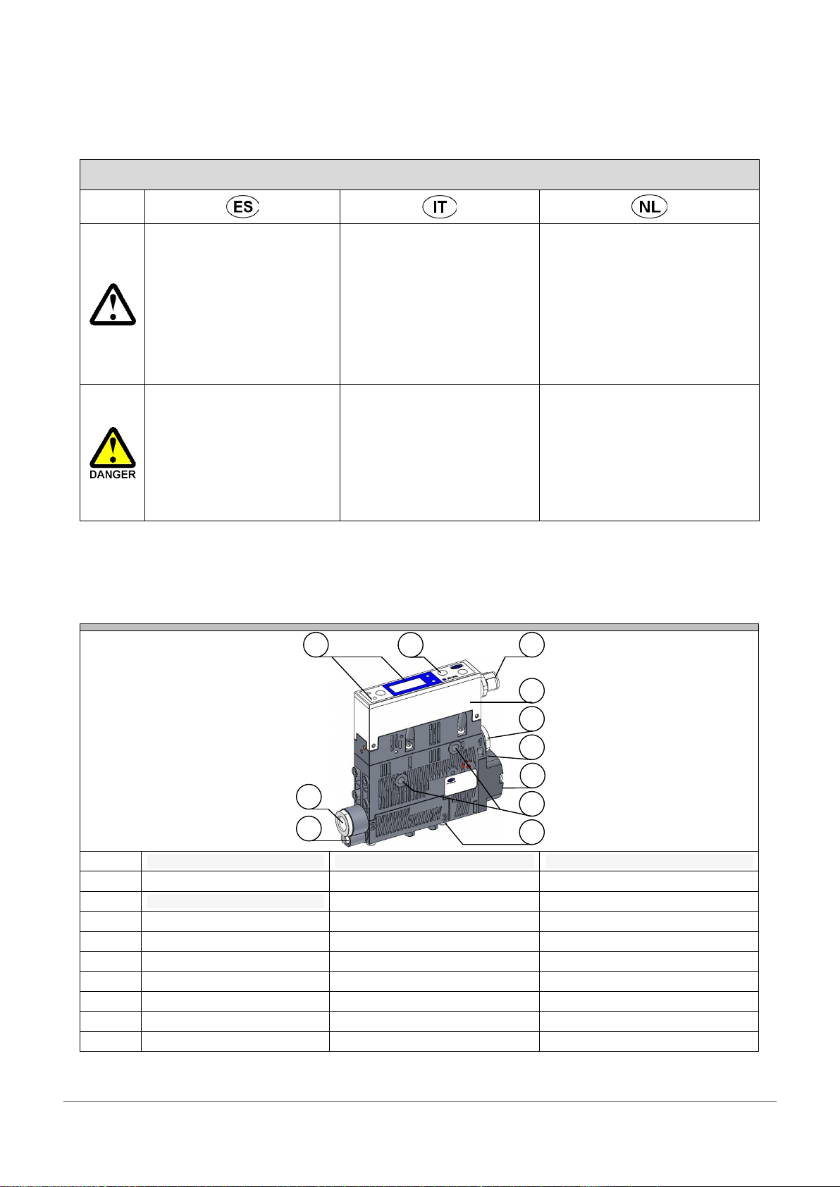
2Estructura del aparato / Struttura dell'apparecchio /
Opbouw van de apparatuur
1
Visualización de estado del proceso
Visualizzazione di stato del processo
Geven van proces-state
2
Elemento de manejo
Elemento di comando
Bedieningselement
3
Acelerador tornillo de purga
Acceleratore colpo vite Off
Throttle schroef Blow Off
4
Conexión de vacío G1/8“
Attacco per vuoto G1/8"
Vacuümaansluiting G1/8”
5
Conexión eléctrica M12-5
Collegamento elettrico M12-5
Elektrische aansluiting M12-5
6
Control
Comando
Besturing
7
Orificios de fijación para M4
Fori di fissaggio per M4
Montageboorgaten voor M4
8
Conexión de aire comprimido G1/8“
Attacco aria compressa G1/8“
Persluchtaansluiting G1/8“
9
Cubierta del silenciador
Copertina del silenziatore
Cover van de geluiddemper
10
Salida de escape
Scarico
Uitlaat
3
4
1 5
6
8
7
9
(max. 4Nm)
(max. 4Nm)
10
2
10
(max. 2Nm)
9 | DE/EN/FR/ES/IT/NL © J. Schmalz GmbH · 30.30.01.00660 · 00 · 07/2014
3Ajuste (parcial) / Impostazione (parziale) / Instelling
(gedeeltelijk)
H-1 / h-1
Ajuste del umbral de conmutación de
la regulación de ahorro de aire
Impostazione della soglia d'intervento
del dispositivo di risparmio dell'aria
Instelling van de schakeldrempel van de
luchtspaarregeling
H-2 / h-2
Ajuste del umbral de conmutación del
control de las piezas
Impostazione della soglia d'intervento
del controllo pezzi
Instelling van de schakeldrempel van de
onderdelen-controle
tbl
Ajuste del tiempo de soplado
Impostazione del tempo di soffiaggio
Instelling van de afblaastijd
CAL
Ajuste del punto cero para el sensor
de vacío
Impostazione origine per sensore di
vuoto
Nulpunt-instelling voor vacuüm- sensor
Seguir con h-1
Continua con h-1
Verder bij h-1
Ajuste del
valor
Impostazione
del valore
Instelling van
de waarde
El valor parpadea
para confirmar
Il valore lampeggia
per conferma
Waarde knippert
ter bevestiging
parpadeo
lampeggiante
knipperen
> 2 sec.
> 2 sec.
> 2 sec.
blinken
flashing
clignotement
10 | DE/EN/FR/ES/IT/NL © J. Schmalz GmbH · 30.30.01.00660 · 00 · 07/2014
4Conexión eléctrica / Collegamento elettrico /
Elektrische aansluiting
SIO
IO-Link
SCPSi –xx –xx –xx –M12-5
US/A (24VDC)
BN
1
M12
1
BN
US/A (24VDC)
Aspirar / Aspirazione / Zuigen
WH
2
2
WH
-
GndS/A
BU
3
3
BU
GndS/A
H2
BK
4
4
BK
C/Q (IO-Link)
Descargar / Soffiaggio / Afblazen
GY
5
5
GY
-
5Parámetros de funcionamiento / Parametri operativi /
Operationele parameters
Parámetros de operación eléctrica / Parametri di funzionamento elettricamente /
Bedrijfsparameters elektrisch
min
typ
max
Tensión de alimentación
Tensione di alimentazione
Voedingsspanning
US/A
19,2
24
26,4
VDC
Intensidad nominal (US/A)
Corrente nominale (US/A)
Nominale stroom (US/A)
SCPSi –xx –NO
IS/A
-
120
-
mA
SCPSi –xx –NC
IS/A
-
70
-
mA
Corriente de salida (PNP)
Corrente di uscita (PNP)
Uitgangsstroom (PNP)
IO
-
-
150
mA
Corriente de salida (NPN)
Corrente di uscita (NPN)
Uitgangsstroom (NPN)
IO
-
-
100
mA
Parámetros de funcionamiento neumáticamente / Parametri di funzionamento pneumaticamente /
Bedrijfsparameters pneumatisch
Presión de trabajo
Pressione di esercizio
Werkdruk
p
2
4
6
bar
Consumo de aire
Consumo d'aria
Luchtverbruik
SCPSi 2-07
Q
24
25
SCPSi 2-09
Q
37
42
SCPSi 2-14
Q
87
101
US/ UA
BUS I/O
US/ UA
BUS IO-Link
11 | DE/EN/FR/ES/IT/NL © J. Schmalz GmbH · 30.30.01.00660 · 00 · 07/2014
IO-Link Comunicación / Comunicazione / Communicatie
SIO-Mode
SIO-Mode
SIO-Mode
Yes
Frame-Typ
Frame-Type
Frame-Typ
2_V
Tasa de baudios
Baudrate
Baudrate
38,4 kBd
Tiempo mínimo de ciclo
Tempo ciclo minimo
Minimale cyclustijd
3,3 ms
Datos de proceso input / output
Dati di processo input/output
Procesdata input / output
4 byte / 2 byte
IO-Link Datos de proceso / Dati di processo / Procesdata
I
O
-
Li
n
k
D
a
t
o
s
d
e
p
r
o
c
e
s
o
/
D
a
ti
di
p
r
o
c
e
ss
o
/
P
r
o
c
e
s
d
a
t
a
Bit
PD-In Byte 0
0
H2 (Control de piezas)
H2 (controllo pezzi)
H2 (Onderdelen-controle)
1
H1 (Regulación)
H1 (regolazione)
H1 (Regeling)
5
Estado del sistema verde
Stato del sistema verde
Systeemstatus groen
6
Estado del sistema amarillo
Stato del sistema giallo
Systeemstatus geel
7
Estado del sistema rojo
Stato del sistema rosso
Systeemstatus rood
PD-Out Byte 0
0
Aspirar ON/OFF
Aspirazione ON/OFF
Zuigen AAN/UIT
1
Descargar ON/OFF
Soffiaggio ON/OFF
Afblazen AAN/UIT
2
Modo de ajuste ON/OFF
Modo di installazione ON/OFF
Instelmodus AAN/UIT
6
Config d perf de proucc, Bit 0
Prod installaz profilo, Bit 0
Productie profiel setup, Bit 0
7
Config d perf de proucc, Bit 1
Prod installaz profilo, Bit 1
Productie profiel setup, Bit 1

Todos los datos de proceso ver
instrucciones detalladas
Tutti i dati di processo vedere
istruzioni dettagliate
Alle Process data zie gedetailleerde
gebruiksaanwijzing
IO-Link Parámetros (parciales) / Parametri (parziali) / Parameters (gedeeltelijk)
64
2
Sistema de vacío
Sistema di vuoto
Systeem vacuüm
130
1
Código de error
Codice di errore
Foutcode
146
1
Código de advertencia
Codice di avviso
Waarschuwingscode
68
1
Función de ahorro de aire
Funzione di risparmio Air
Air saving functie
78
1
Desactivar la continua succión
Disabilitare continuo succhiare
Uitschakelen continue zuigen
100
2
Punto de conmutación H1
Punto di commutazione H1
Schakelpunt H1
101
2
Histéresis h1
Isteresi h1
Hysteresis h1
102
2
Punto de conmutación H2
Punto di commutazione H2
Schakelpunt H2
103
2
Histéresis h2
Isteresi h2
Hysteresis h2
106
2
Tiempo Blow-off
Tempo di Blow-off
Blow-off tijd
107
2
Tiempo de evacuación permitida
Toegestane evacuatietijd
108
1
Valor de fuga admisible
Valore di trafilamento
Toegestane lekwaarde
69
1
Modo de Blow-off
Modalità di Blow-off
Blow-off-stand
71
1
Función OUT2
Funzione OUT2
Functie OUT2
73
1
Tipo de señal
Tipo di segnale
Signaaltype
74
1
Unidad de visualización de vacío
Unità display vuoto
Vacuüm beeldscherm
75
1
Retardo de desconexión
Ritardo di spegnimento
Uitschakelvertraging
79
1
Rotación de la pantalla
Rotazione del display
Rotatie van het beeldscherm
76
1
Eco-Mode
Eco-Mode
Eco-modus
77
2
PIN-Code
PIN-Code
PIN-Code

Para todos los parámetros,
véanse las instrucciones de
servicio completas
Per tutti i parametri vedere la
versione integrale delle Istruzioni
per l’uso
Alle parameters zie uitvoerlijke
bedieningsinstructies
12 | DE/EN/FR/ES/IT/NL © J. Schmalz GmbH · 30.30.01.00660 · 00 · 07/2014
Anzeigesymbole Übersicht / Overview of display symbols
Symbol
Funktion
Bemerkung
Schaltpunkt H1
Switching point H1
Ausschaltwert der Luftsparfunktion
Switch-off value for the air-saving function
Hysterese h1
Hysteresis h1
Hysterese der Luftsparfunktion
Hysteresis of the air-saving function
Schaltpunkt H2
Switching point H2
Einschaltwert Signalausgang „Teilekontrolle“
Switch-on value for the “part present control” signal output
Hysterese h2
Hysteresis h2
Hysterese Signalausgang „Teilekontrolle“
Hysteresis of “part present control” signal output
Abblaszeit
Blow-off time
Einstellung der Abblaszeit für zeitgesteuertes Abblasen
Blow-off time setting for time-controlled blow-off
Nullpunkteinstellung
Zero-point adjustment
Kalibrierung des Vakuumsensors
Calibration oft he vacuum sensor
Gesamtzähler 1
Total counter 1
Zähler für Saugzyklen (Signaleingang „Saugen“)
Counter for suction cycles (suction signal input)
Gesamtzähler 2
Total counter 2
Zähler für Ventilschalthäufigkeit
Counter for valve switching frequency
Softwareversion
Software version
Zeigt die aktuelle Softwareversion an
Displays the current software version
Artikelnummer
Article number
Zeigt die Artikelnummer des Ejektors an
Displays the article number of the ejector
Seriennummer
Serial number
Zeigt die Seriennummer des Ejektors an
Displays the serial number of the ejector
Luftsparfunktion
Air-saving function
Einstellung der Luftsparfunktion
Setting for the air-saving function
Luftsparfunktion ein
Air-saving function on
Einschalten der Luftsparfunktion
Activation of the air-saving function
Luftsparfunktion ein mit
Leckageüberwachung
Air-saving function on with
leakage monitoring
Einschalten der Luftsparfunktion mit Leckageüberwachung
Switching on the air-saving function with leakage monitoring
Luftsparfunktion aus
Air-saving function off
Ausschalten der Luftsparfunktion
Deactivation of the air-saving function
Dauersaugen deaktivieren
Deactivate continuous suction
Freigabe des Dauersaugens
Enabling continuous suction
Dauersaugen deaktiviert
Air-saving function on
Auswahl Dauersaugen ist deaktivieren
Activation of the air-saving function
Dauersaugen ist aktiviert
Air-saving function off
Auswahl Dauersaugen ist aktivieren
Deactivation of the air-saving function
Evakuierungszeit
Evacuation time
Einstellung der maximal zulässigen Evakuierungszeit
Setting for the maximum permitted evacuation time
Leckagewert
Leakage value
Einstellung der maximal zulässigen Leckage
Setting for the maximum permitted leakage
Abblasfunktion (blow off)
Blow-off function
Menü zum Konfigurieren der Abblasfunktion
Menu for configuring the blow-off function
Abblasen „Extern“
“External” blow-off
Auswahl extern gesteuertes Abblasen (externes Signal)
Selection of externally controlled blow-off (external signal)
13 | DE/EN/FR/ES/IT/NL © J. Schmalz GmbH · 30.30.01.00660 · 00 · 07/2014
Abblasen „Intern“
“Internal” blow-off
Auswahl intern gesteuertes Abblasen (intern ausgelöst, Zeit
einstellbar)
Selection of internally controlled blow-off (triggered internally; time
can be set)
Selection of internally controlled blow-off (triggered internally; time
can be set)
Abblasen „Extern
zeitgesteuert“
“Externally time-controlled”
blow-off
Auswahl extern gesteuertes Abblasen (extern ausgelöst, Zeit
einstellbar)
Selection of externally controlled blow-off (triggered externally; time
can be set)
Konfig. Signalausgang
Config. Signal output
Menü zum Konfigurieren des Signalausgangs
Menue for Configuration of the signal output
Schließerkontakt
Normally open contact
Einstellung des Signalausgangs als Schließerkontakt
Setting the signal output as a normally open contact
Öffnerkontakt
Normally closed contact
Einstellung des Signalausgangs als Öffnerkontakt
Setting the signal output as a normally closed contact
Konfiguration Signaltyp
Config of signal type
Menü zur Konfiguration des Signaltyps (NPN / PNP)
Menu for configuring the signal type (NPN/PNP)
Signaltyp PNP
PNP signal type
Alle Eingangs- und Ausgangssignale sind PNP-schaltend
All input and output signals switch according to PNP
Signaltyp NPN
NPN signal type
Alle Eingangs- und Ausgangssignale sind NPN-schaltend
All input and output signals switch according to NPN
Vakuumeinheit (unit)
Vacuum unit
Vakuumeinheit, in welcher der Messwert und die Einstellwerte
angezeigt werden
Vacuum unit in which the measurement and setting values are
displayed
Vakuumwert in mbar
Vacuum value in mbar
Die angezeigten Vakuumwerte haben die Einheit mbar.
Shown Vacuum values in mbar
Vakuumwert in kPa
Vacuum value in kPa
Die angezeigten Vakuumwerte haben die Einheit kPa.
Shown Vacuum values in kPa
Vakuumwert in inHg
Vacuum value in Hg
Die angezeigten Vakuumwerte haben die Einheit inchHg.
Shown Vacuum values in Hg
Ausschaltverzögerung
Switch-off delay
Einstellen der Ausschaltverzögerung für OUT2
Setting for the switch-off delay for OUT2
Rotation Display
Rotation display
Einstellung der Displaydarstellung (Drehung)
Setting oft he Display Rotation
Anzeige Standard
Display Standard
Display nicht gedreht
Display not rotated
Anzeige gedreht
Display rotated
Display um 180° rotiert
Display rotated 180°
ECO-Mode
ECO-Mode
Einstellen des ECO-Mode
Setting the ECO-Mode
ECO-Mode an
ECO-Mode on
ECO-Modus aktiviert –Display schaltet ab
ECO-Mode activated –Display switches off
Kein ECO-Modus
No ECO-Mode
ECO-Modus deaktiviert –Display dauerhaft an
ECO-Mode deactivated –Display on
PIN-Code
PIN-Code
Eingabe des Pincode zur Freigabe der Verriegelung
Enter the PIN to unlock the menu
Menü gesperrt (lock)
Menu locked
Das Ändern von Parametern ist blockiert.
A lock prevents parameters from being changed
Menü entsperrt
Menu unlocked
Die Tasten und Menüs sind freigegeben.
The buttons and menus are unlocked.
Reset
Reset
Alle einstellbaren Werte werden auf Werkseinstellungen
zurückgesetzt.
All values that can be changed are reset to the factory settings.

This manual suits for next models

2

Other Schmalz Industrial Equipment manuals

Schmalz VCBL-A-K1 User manual

Schmalz

Schmalz VCBL-A-K1 User manual

Schmalz SLP 05 User manual

Schmalz

Schmalz SLP 05 User manual

Schmalz SSP User manual

Schmalz

Schmalz SSP User manual

Schmalz VWT-180-4 User manual

Schmalz

Schmalz VWT-180-4 User manual

Schmalz 10.01.38.06443 User manual

Schmalz

Schmalz 10.01.38.06443 User manual

Schmalz FXP-i User manual

Schmalz

Schmalz FXP-i User manual

Schmalz VCMC-S4 QUICK User manual

Schmalz

Schmalz VCMC-S4 QUICK User manual

Schmalz SCP AS-RP Series User manual

Schmalz

Schmalz SCP AS-RP Series User manual

Schmalz SPZ User manual

Schmalz

Schmalz SPZ User manual

Schmalz SNGi-AE User manual

Schmalz

Schmalz SNGi-AE User manual

Schmalz FMHD User manual

Schmalz

Schmalz FMHD User manual

Schmalz SPZ User manual

Schmalz

Schmalz SPZ User manual

Schmalz SSP User manual

Schmalz

Schmalz SSP User manual

Schmalz EVE-TR 4 - 8 DC User manual

Schmalz

Schmalz EVE-TR 4 - 8 DC User manual

Schmalz VacuMaster Window User manual

Schmalz

Schmalz VacuMaster Window User manual

Schmalz SCGS User manual

Schmalz

Schmalz SCGS User manual

Schmalz FXP-i User manual

Schmalz

Schmalz FXP-i User manual

Schmalz FXP Series User manual

Schmalz

Schmalz FXP Series User manual

Schmalz 10.01.11.02295 User manual

Schmalz

Schmalz 10.01.11.02295 User manual

Schmalz FXCB User manual

Schmalz

Schmalz FXCB User manual

Schmalz SCPSb-07 User manual

Schmalz

Schmalz SCPSb-07 User manual

Schmalz SSP User manual

Schmalz

Schmalz SSP User manual

Schmalz FXCB User manual

Schmalz

Schmalz FXCB User manual

Schmalz SCPSb-2 User manual

Schmalz

Schmalz SCPSb-2 User manual

Popular Industrial Equipment manuals by other brands

ESAB Warrior Feed 304 instruction manual

ESAB

ESAB Warrior Feed 304 instruction manual

Siemens SIVACON 8PS BD2 Series installation instructions

Siemens

Siemens SIVACON 8PS BD2 Series installation instructions

3M Attest Auto-reader 490 Operator's manual

3M

3M Attest Auto-reader 490 Operator's manual

SCHUNK Vario D operating manual

SCHUNK

SCHUNK Vario D operating manual

SKF TMMA 100H/SET Instructions for use

SKF

SKF TMMA 100H/SET Instructions for use

bon 24-515 instructions

bon

bon 24-515 instructions

CLEAN ROOM DEVICES CRD500SS Operation manual

CLEAN ROOM DEVICES

CLEAN ROOM DEVICES CRD500SS Operation manual

Rinnai MP2200 Operation & installation manual

Rinnai

Rinnai MP2200 Operation & installation manual

steute STM 295 Mounting and wiring instructions

steute

steute STM 295 Mounting and wiring instructions

Behncke EWT 80-40 installation instructions

Behncke

Behncke EWT 80-40 installation instructions

ABB HT593639 Operation manual

ABB

ABB HT593639 Operation manual

ABB AF190-30 operating instructions

ABB

ABB AF190-30 operating instructions

ABB HT842210 Operation manual

ABB

ABB HT842210 Operation manual

Kitagawa DL200 instruction manual

Kitagawa

Kitagawa DL200 instruction manual

HEUTE ProfilGate i45 aqua operating manual

HEUTE

HEUTE ProfilGate i45 aqua operating manual

Wisi OM 17A operating instructions

Wisi

Wisi OM 17A operating instructions

Festo EGSC-BS-KF operating instructions

Festo

Festo EGSC-BS-KF operating instructions

KINSHOFER EuroRail Operator's guide

KINSHOFER

KINSHOFER EuroRail Operator's guide

manuals.online logo
manuals.online logoBrands
  • About & Mission
  • Contact us
  • Privacy Policy
  • Terms and Conditions

Copyright 2025 Manuals.Online. All Rights Reserved.