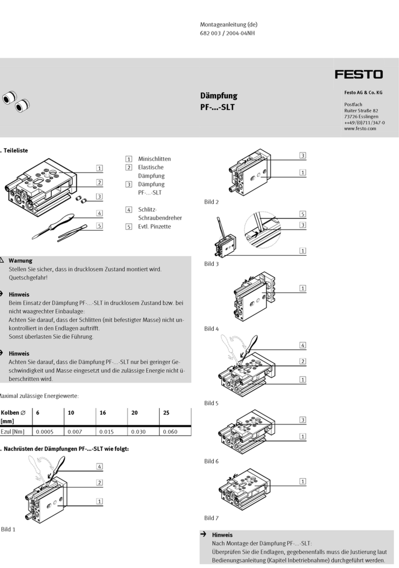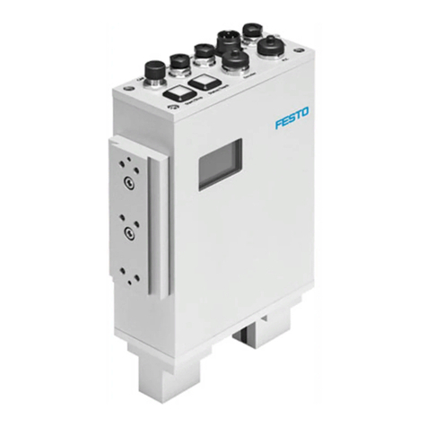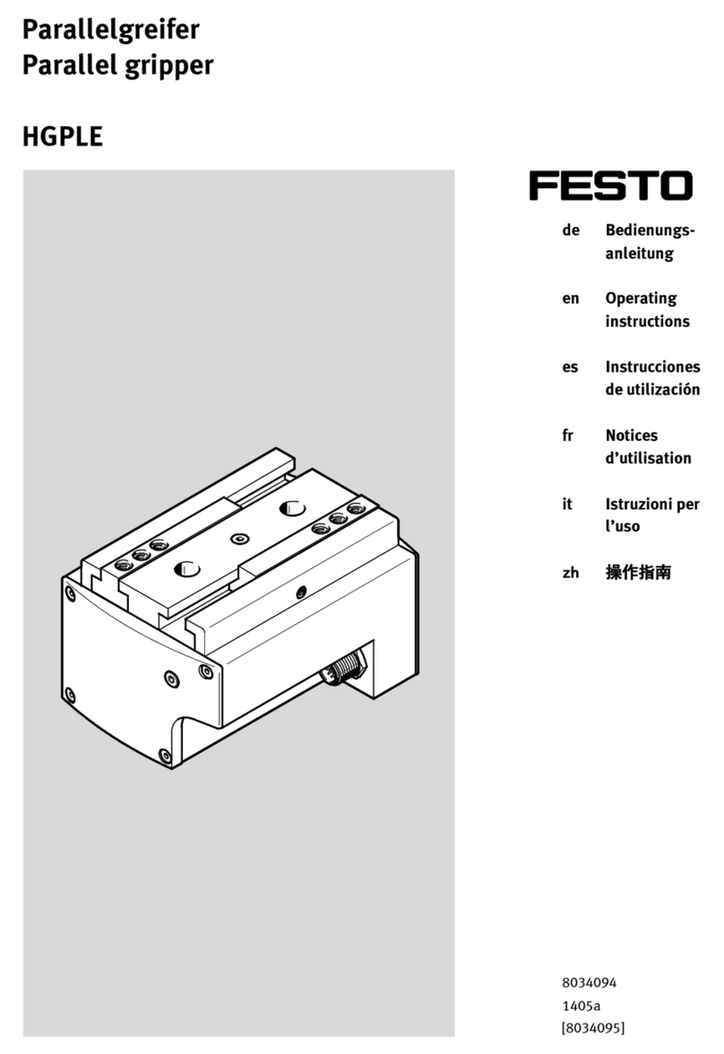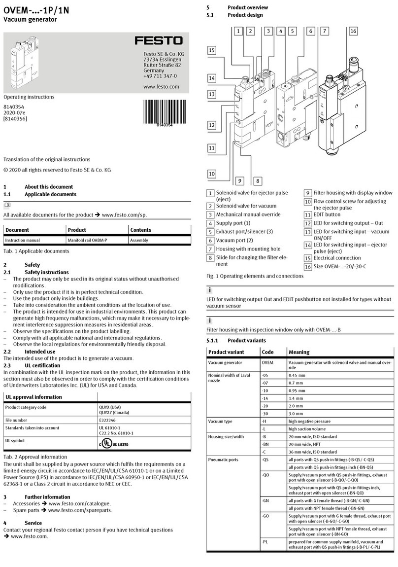
Fault description Cause Remedy
Piston rod does not
move
Operation at the lower
ambient temperature
limit
–Reduce velocity or force
Idling torque too high Wear in the drivetrain –Contact local Festo Service.
–Replace cylinder
è www.festo.com/catalogue.
Tab. 15: Overview of fault clearance
11.2 Repair
Repair or maintenance of the product is not permissible.
–Replace with an identical product è www.festo.com/spareparts.
12 Replacement
1. Save the application parameters to the IO-Link master è "Integrated drive
EMCS" instruction manual è www.festo.com/sp.
2. Demount the drive system è 13 Demounting.
3. Mount the drive system è 6 Assembly.
4. Connect the drive system è 7 Installation.
5. Commission the drive system è 8 Commissioning.
6. Update the firmware è "Integrated drive EMCS" instruction
manual è www.festo.com/sp.
7. Check the current status of the application data è "Integrated drive EMCS"
instruction manual è www.festo.com/sp.
13 Demounting
WARNING
Unexpected movement of components.
Injury due to impacts or crushing.
• Before working on the product, switch off the control and secure it to prevent it
from being switched back on accidentally.
WARNING
Risk of Injury due to Unexpected Movement of Components
For vertical or slanted mounting position: when power is off, moving parts can
travel or fall uncontrolled into the lower end position.
•Bring moving parts of the product into a safe end position or secure them
against falling.
Demount drive system
1. Allow the product to cool down to room temperature.
2. Disconnect electrical installations.
3. Remove the mounted attachment component.
4. Remove the attached accessories.
5. Remove the mounting attachments.
6. Observe transport information è 5 Transport.
Remove drive or integrated drive EMCS è "Integrated drive EMCS" instruction
manual è www.festo.com/sp.
14 Technical data
Additional information è www.festo.com/catalogue.
Size 45 60
Design Electric cylinder with toothed belt and integrated
drive
Guide Plain-bearing guide
Mounting position any
Ambient temperature [°C] 0 … +50
Storage temperature [°C] –20 … +60
Degree of protection IP40
EMCS-ST: Certificates, declaration
of conformity
è www.festo.com/sp
Max. payload
–horizontal mounting position [kg] 5 10
–vertical mounting position [kg] 2.5 5
Max. feed force Fx (sum of all
piston rods)1)2)
[N] 85 150
Max. force on external stops
during homing3)
[N] 97 186
Max. velocity4) [m/s] 0.44 0.6
Velocity "Speed Press"5) [mm/s] 20 20
Max. acceleration/deceleration5) [m/s2]9 9
Duty cycle [%] 100 (+30 … +50 °C: – 2% per Kelvin)
Min. stop/end position distance6) [mm] 0.5
Repetition accuracy [mm] ±0.05
Feed constant [mm/
rev]
32 32
Nominal voltage [V DC] 24
Logic current consumption (logic,
pin 1)
[mA] DIO operation: 100 ... 300
IO-Link operation: 100 ... 150
Load current consumption (power,
pin 1)
[A] 3 5.3
Size 45 60
IO-Link port class A
IO-Link protocol version Device V 1.1
Max. permitted forces and torques on the piston rod
Fy [N] è Transverse load on piston rod EPCE-TB
Fz [N] è Transverse load on piston rod EPCE-TB
Mx [Nm] 0 0
My [Nm] 0.4 1
Mz [Nm] 0.4 1
Calculating the load comparison factor
fv
1) Maximum value for Force at level 10
2) Force is controlled and evaluated by closed-loop control of the motor current. Depending on the mecha-
nism of the drive, a linear force can be calculated from the measured level of current. The target is set as
a percentage of the rated motor current and may differ from the actual force at the electric cylinder. At the
lower force levels the frictional force of the drive system may be greater than the set feed force and may
result in the drive system coming to a standstill.
3) The force acts on the stop for £100 ms
4) Maximum value for Speed In/Speed Out at level 10
5) Unchangeable parameter.
6) Distance (MechIn – LimIn or MechOut – LimOut)
Tab. 16: General data, EPCE-TB
Size 45 60
Materials
Note on materials Contains paint-wetting impairment substances
Housing Anodised aluminium
Blanking plate Anodised aluminium
Piston rod High-alloy steel
Cover sheet Steel
Toothed belt Polychloroprene with glass cord and nylon coating
Weight
Basic weight at 0 mm stroke [kg] 0.8 1.4
Additional weight per 10 mm
stroke (for variant with one
piston rod)
[kg] 0.03 0.045
Tab. 17: Materials and weight
14.1 Characteristic curves
Additional information è www.festo.com/catalogue.
Transverse load on piston rod EPCE-TB
Max. transverse load Fy, Fz on the piston rod as a function of the piston rod length
l
Fig. 10: Max. transverse load Fy, Fz and piston rod length l
Fig. 11: EPCE, max. transverse load Fy, Fz as a function of the piston rod length l
EPCE-TB-45
EPCE-TB-60
EPCE-TB-45-MB/-MD/-MF
EPCE-TB-60-MB/-MD/-MF

