Schmidt SS 20.260 User manual

SCHMIDT®Flow Sensor
SS 20.260
Instructions for Use

Instructions for Use –SCHMIDT®Flow sensor SS 20.260 Page 2
SCHMIDT®Flow Sensor
SS 20.260
Table of Contents
1Important information.......................................................................3
2Application range.............................................................................4
3Mounting instructions.......................................................................4
4Electrical connection......................................................................11
5Signalization..................................................................................12
6Startup...........................................................................................14
7Information concerning operation..................................................15
8Service information........................................................................16
9Technical data ...............................................................................18
10 Declaration of conformity...............................................................19
Imprint:
Copyright 2020 SCHMIDT Technology GmbH
All rights reserved
Version 508981.02H
Subject to modifications

Instructions for Use –SCHMIDT®Flow sensor SS 20.260 Page 3
1 Important information
The instructions for use contain all required information for a fast commis-
sioning and a safe operation of the SCHMIDT®Flow sensor SS 20.260:
These instructions for use must be read completely and observed
carefully, before putting the unit into operation.
Any claims under the manufacturer's liability for damage resulting
from non-observance or non-compliance with these instructions will
become void.
Tampering with the device in any way whatsoever - with the exception
of the designated use and the operations described in these instruc-
tions for use - will forfeit any warranty and exclude any liability.
The unit is designed exclusively for the use described below (see
chapter 2). In particular, it is not designed for direct or indirect protec-
tion of personal or machinery.
SCHMIDT Technology cannot give any warranty as to its suitability
for certain purpose and cannot be held liable for accidental or sequen-
tial damage in connection with the delivery, performance or use of this
unit.
Symbols used in this manual
The symbols used in this manual are explained in the following section.
Danger warnings and safety instructions –read them care-
fully!
Non-observance of these instructions may lead to injury of per-
sonnel or malfunction of the device.
General note
All dimensions are indicated in mm.
!

Instructions for Use –SCHMIDT®Flow sensor SS 20.260 Page 4
2 Application range
The SCHMIDT®Flow sensor SS 20.260 (article number: 506690) is de-
signed for stationary measurement of the flow velocity as well as the tem-
perature of pure
1
air and gases under atmospheric pressure.
The sensor is based on the measuring principle of a thermal anemometer
and measures the mass flow of the measuring medium as flow velocity
which is output in a linear way as standard velocity
2
wN (unit: m/s), based
on standard conditions of 1013.25 hPa and 20 °C. Thus, the resulting out-
put signal is independent of pressure and temperature of the medium to
be measured. The sensor is designed for the use inside closed rooms and
is not suitable for outdoor use.
When using the sensor outdoors, it must be protected against
direct exposure to the weather.
3 Mounting instructions
General information on handling
The SS 20.260 is a precision instrument with high measuring sensitivity.
In spite of the robust construction of the sensor tip soiling of the inner sen-
sor elements can lead to distortion of measurement results (see also chap-
ter 8). During procedures that could yield soiling like transport, mounting
or dismounting of the sensor it is recommended to place the enclosed
SCHMIDT Technology protective cap on the sensor tip and remove it only
during operation.
During processes with enhanced risks of soiling such as
transport or mounting the protective cap should be placed onto
the sensor tip.
General installation conditions
The sensor measures the flow speed correctly only in the direction given
on the housing and sensor head (arrow). Make sure that the sensor is
adjusted in flow direction (see Figure 1); a tilting of up to ±3° is allowed
3
.
The sensor measures unidirectional and must be adjusted cor-
rectly relative to the flow direction.
1
No chemically aggressive parts / abrasive particles. Check suitability in individual cases.
2
Corresponds to the actual flow velocity under standard conditions.
3
Measurement deviation < 1 %
!
!
!

Instructions for Use –SCHMIDT®Flow sensor SS 20.260 Page 5
The sensor should preferably be installed in horizontally positioned pipes.
A sensor mounted in opposite direction of the flow direction leads to wrong
measuring values (too high).
Due to system characteristics the lower measuring range limit of
the sensor is 0.2 m/s.
At lower flow velocities (< 2 m/s), the measured medium tem-
perature is too high.
The center of the chamber head is the actual measuring point of the flow
measurement and must be placed in the flow as advantageous as possi-
ble, for example in the middle of a pipe (see Figure 1). Therefore, this point
is also used for specification of probe length L (see Figure 2).
Figure 1 Positioning in a pipe
Always position the sensor head, if possible, in the middle of the
pipe or shaft.
Installation with low disturbance
Local turbulences of the medium can cause distortion of measurement
results. Therefore, appropriate mounting conditions must be guaranteed
to ensure that the gas flow is supplied to the sensor in a quiet state and
low in turbulence in order to maintain the accuracy specified (see chapter
9).
Correct measurements require quiet flow, as low-turbulence as
possible.
An undisturbed flow profile can be achieved if a sufficiently long distance
in front of (run-in distance) and behind (run-out distance) the sensor in-
stallation site (see Figure 2) is held absolutelystraight and without disturb-
ances (such as edges, seams, bends etc.). It is also necessary to pay
attention to the design of the run-out distance because disturbances also
generate turbulences against the flow direction.
!
!
!
!
Flow
Direction of measurement

Instructions for Use –SCHMIDT®Flow sensor SS 20.260 Page 6
L
= Length of entire measuring distance
L1
= Length of run-in distance
L2
= Length of run-out distance
D
= Inner diameter of measuring distance
Figure 2
The following Table 1 shows the required straight conduit lengths depend-
ing on the pipe inner diameter “D” and the different disturbance causes.
Flow obstacle upstream of the measuring distance
Minimum length of distance
Run-in L1
Run-out L2
Light bend (< 90°)
10 x D
5 x D
Reduction / expansion / 90° bend or T-junction
15 x D
5 x D
Two 90° bends in one plane (2-dimensional)
20 x D
5 x D
Two 90° bends (3-dimensional change in direction)
35 x D
5 x D
Shut-off valve
45 x D
5 x D
Table 1
This table lists the minimum values required in each case. If it is not pos-
sible to observe the specified abatement distances, increased deviations
of the measurement results are to be expected or it is necessary to take
additional measures
4
. The profile factors specified in Table 2 may become
void by the use of flow rectifiers.
Calculation of volume flow
If the cross section area of the pipe is known, the output signal of the flow
speed wNcan be used to calculate the standard volumetric flow of the
medium. By means of a correction factor PF
5
, which depends on the pipe
diameter D the measured value can be converted to an averaged flow
velocity
N
w
which is constant over the whole pipe cross-section.
Thus, it is possible to calculate the standard volumetric flow of the medium
using the measured standard flow velocity in a pipe with known inner di-
ameter:
4
Alternatively, flow rectifiers could be used, e.g. honeycombs made of plastic or ceramics.
5
Considers the flow profile and sensor obstruction.

Instructions for Use –SCHMIDT®Flow sensor SS 20.260 Page 7
3600
42
AwV
wPFw
DA
NN
NN
Table 2 lists profile factors and volume flow measuring ranges (with cer-
tain sensor measuring ranges) for standard pipe diameters.
Table 2
Inner Min. @
DN [inch]
[mm] PF 0.2 m/s 2.5 m/s 20 m/s 50 m/s
25 25 126.0 0.796 0.30 3.80 30.4 76.1
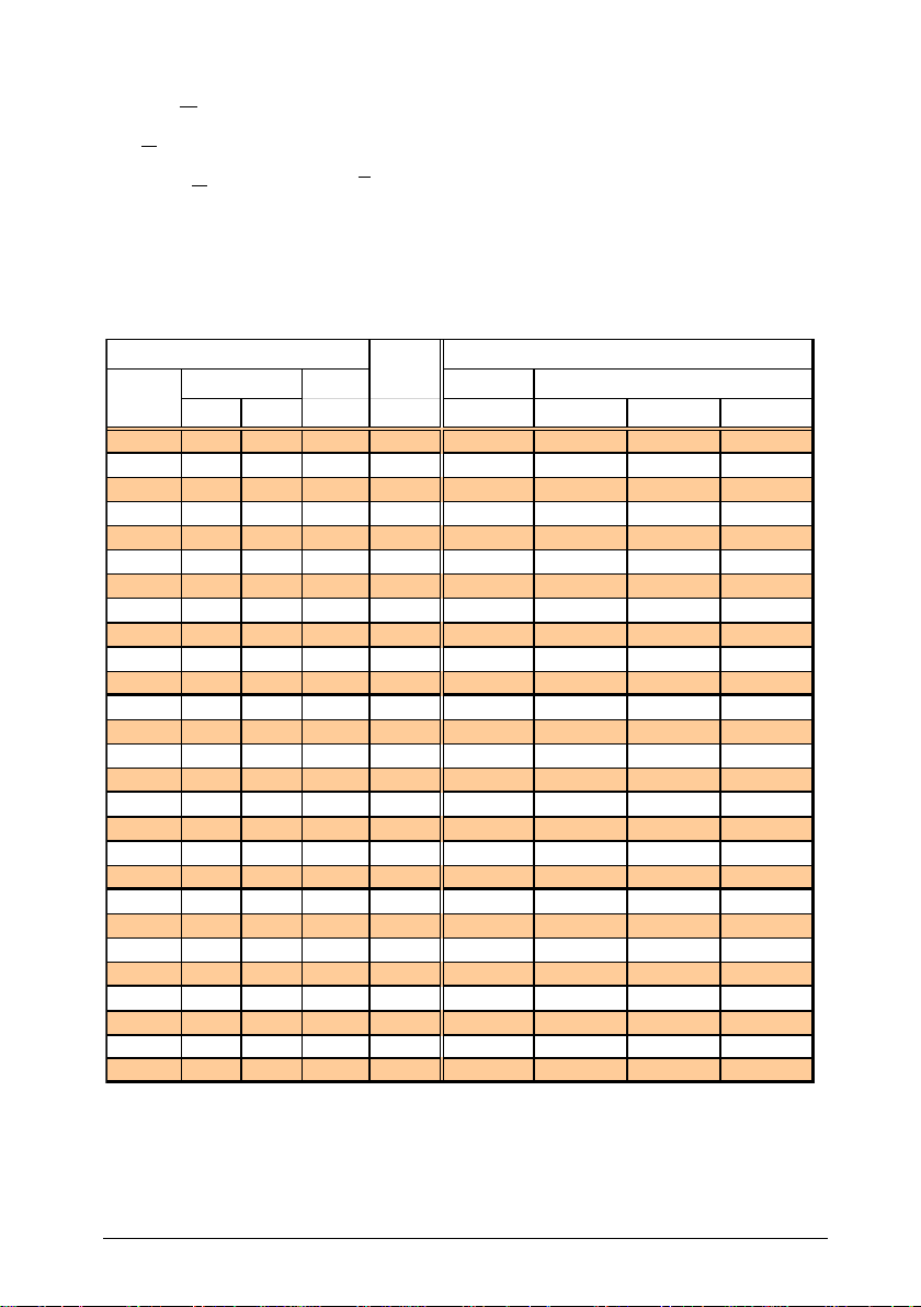
32 32.8 0.796 0.48 6.05 48.4 121
1 1/4 36.3 0.770 0.57 7.17 57.4 143
40 40 1 1/2 39.3 0.748 0.65 8.17 65.3 163
43.1 0.757 0.80 9.94 79.5 199
45.8 0.763 0.91 11.3 90.5 226
50 50 2 51.2 0.772 1.14 14.3 114 286
57.5 0.777 1.45 18.2 145 363
65 65 2 1/2 70.3 0.786 2.20 27.5 220 549
76.1 0.792 2.59 32.4 259 648
80 80 3 82.5 0.797 3.07 38.3 307 767
100 100 4 100.8 0.804 4.62 57.7 462 1.155
125 125 5 125.0 0.812 7.17 89.7 717 1.794
150 150 6 150.0 0.817 10.4 130 1.040 2.599
180 182.5 0.825 15.5 194 1.554 3.885
200 200 8 206.5 0.829 20.0 250 1.999 4.998
250 10 260.4 0.835 32.0 400 3.202 8.004
300 300 12 309.7 0.840 45.6 570 4.556 11.390
350 14 339.6 0.842 54.9 686 5.491 13.728
400 400 16 389 0.845 72.2 903 7.223 18.058
450 450 18 437 0.847 91.5 1.143 9.147 22.867
500 500 20 486 0.850 114 1.419 11.353 28.383
600 600 24 585 0.854 165 2.066 16.527 41.317
700 700 28 684 0.857 227 2.834 22.673 56.683
800 800 32 783 0.859 298 3.723 29.781 74.452
900 900 36 882 0.862 379 4.740 37.920 94.800
1000 1000 40 980 0.864 469 5.865 46.923 117.308
Nominal
size
Diameter of measuring pipe
Profile
faktor
Measuring range of volumetric flow [m3/h]
Norm value
@ sensor measuring range [m/s]
D
Inner diameter of pipe [m]
A
Cross-section area of pipe [m2]
N
w
Flow velocity in the middle of the pipe [m/s]
N
w
Average flow velocity in the pipe [m/s]
PF
Profile factor (for pipes with circular cross-sections)
N
V
Standard volumetric flow [m³/h]

Instructions for Use –SCHMIDT®Flow sensor SS 20.260 Page 8
SCHMIDT Technology provides a convenient calculation tool to compute
flow velocity or volume flow in pipes (circular or rectangular) for all its sen-
sor types and measuring ranges on its homepage:
www.schmidt-sensors.com
Mounting in a wall
The housing has an external thread M18 x 1 (19 mm long) for direct
mounting on or in the medium separating wall. Its advantage lies in the
simplicity of installation without special accessories; however, the probe
length defines the immersion depth in this case and this method requires
access from both sides for operation.
Drill a bore in the wall with 13 … 14 mm diameter.
Carefully insert measuring probe with an attached protection sleeve
into the bore so that the mounting block of the enclosure is in contact
with the wall.
Screw on the enclosed fastening nut by hand on the medium side,
turn sensor into required position and tighten fastening nut (SW22)
while holding up the enclosure on the mounting block by means of
SW30.
Angular deviation should not be greater than 3° relative to
flow direction.
Check the set angular position carefully, for example by means of a
spirit level at the octagonal part of the sensor enclosure.
Finally, remove protective cap from sensor tip.
!

Instructions for Use –SCHMIDT®Flow sensor SS 20.260 Page 9
Mounting with a through-bolt joint
The sensor is installed using a special through-bolt joint (517206). Nor-
mally, a sleeve is welded as a connecting piece onto a bore in the medium-
guiding pipe, in which the external thread (G½) of the through-bolt joint is
screwed (see Figure 3).
Figure 3
L
Sensor length [mm]
DA
Outer diameter of the pipe [mm]
SL
Length of the weld-in sleeve [mm]
E
Sensor tube setting length [mm]
AL
Projecting length [mm]
MID
Minimum immersion depth [mm]
Bore a mounting opening in a pipe wall.
Weld connecting piece with an internal thread G½ resp. Rp½ centered
above the mounting opening of the pipe.
Recommended length of sleeve: 15 ... 40 mm
If necessary wrap thread of through-bolt joint with common sealing
tape, for example made of PTFE.
Screw thread of through-bolt joint by hand into connecting piece then
tighten it firmly with a fork wrench (SW27).
Remove spigot nut of through-bolt joint and extract both seal halves.
Remove protective cap from sensor tip and attach spigot nut on sen-
sor probe.
Insert probe in threaded part of through-bolt joint, attach seal halves
and screw on spigot nut manually to such an extent that the sensor
probe can be inserted without jamming.
In case of a longer sensor probe push it partly into the pipe as re-
quired.
Always avoid bending of the probe tube during screwing.
L
AL
66SL 32
MET=20
8 E
D
A
!
MID = 20

Instructions for Use –SCHMIDT®Flow sensor SS 20.260 Page 10
Carefully slide probe so that the center of the chamber head is placed
at the optimum measuring position in the middle of the pipe.
Tighten spigot nut slightly by hand so that sensor is fixed.
Adjust sensor manually at its enclosure into required measuring direc-
tion and precise position while maintaining immersion depth.
Hold sensor and tighten spigot nut by turning the fork wrench (SW17)
a quarter of a turn.
Recommended torque: 10 … 15 Nm
Check the set angular position carefully, for example by means of a
spirit level at the octagonal part of the sensor enclosure.
Angular deviation should not be greater than 3° relative to
the ideal measuring direction. Otherwise, the measurement
accuracy may be affected.
In case of wrong adjustment, the through-bolt joint has to be loosened
and the alignment procedure must be repeated.
Mounting accessories
Type / art. no.
Drawing
Mounting
Clamp6
a.) 524 916
b.) 524 882
- Internal thread Rp½
- Material:
a.) Steel, black
b.) Stainless steel 1.4571
Compression
fitting
517 206
- Immersion sensor
- Pipe (typ.), wall
- Screwing into a welding stud
- Material:
Brass
PTFE, NBR
Atmospheric pressure use!
Table 3
6
Must be welded.
!
26,6
34
Rp 1/2
51
12
1/2G
SW24
SW27
9

Instructions for Use –SCHMIDT®Flow sensor SS 20.260 Page 11
4 Electrical connection
The sensor is equipped with a 4-pin cable firmly fixed to the sensor enclo-
sure (pin assignment refers to Table 4).
Wire color
Designation
Function
Brown (BR)
Power
Operating voltage: +UB
White (WH)
GND
Operating voltage: Ground
Yellow (YE)
Analog wN
Output signal: Flow velocity
Green (GN)
Analog TMor
AGND
Output signal: Temperature of medium or
Ground connection of analog output
Table 4
During electrical installation ensure that no voltage is applied and
inadvertent activation is not possible.
The cable has a standard length of 2 m, but lengths of 3 up to 100 m can
be ordered optionally.
Operating voltage
For proper operation the sensor requires DC voltage with a nominal value
of 24 V with permitted tolerance of ±10 %. It is protected against a polarity
reversal; typical operating current is 40 mA, at maximum 60 mA
7
.
Only operate sensor within the defined range of operating volt-
age (24 V DC ± 10 %).
Undervoltage may result in malfunction; overvoltage may lead to
irreversible damage to the sensor.
The specifications for the operating voltage are valid for the internal con-
nection of the sensor. Voltage drops generated due to cable resistances
must be considered by the customer.
Analog outputs
The basic sensor variant (“-1”), which measures only flow velocity, can be
ordered with voltage
8
(0 … 10 V) or current interface (4 … 20 mA). The
enhanced version (“-2”) with an additional analog output for signalizing
medium temperature comes with 2 current interfaces. Either type of ana-
log output is short-circuit protected against both rails of the operating volt-
age UB.
7
Both signal outputs 22 mA (maximum measuring values), minimum operating voltage.
8
It is recommended, to use AGND as measuring reference potential for voltage output.
!
!

Instructions for Use –SCHMIDT®Flow sensor SS 20.260 Page 12
Voltage output (wN)
Current interface (wN,TM)
UA= 0 ... 10 V RL≥10 k
IA= 4 ... 20 mA RL≤300
Figure 4
The apparent ohmic resistance RLmust be connected between the signal
output and GND (see Figure 4).
Load capacity CLis limited to a maximum of 10 nF.
5 Signalization
Light emitting diodes
The sensor is equipped with 2 light emitting diodes (LED) indicating its
functional state.
Figure 5
Operating state
LED 1
LED 2
Supply voltage: none, wrong polarity, too low
Sensor ready for operation
Supply voltage beyond specification range or
Medium temperature beyond specification range
Sensor defective
Table 5
LED off
LED flashes (approx. 2 Hz): green
LED on: green
LED flashes (approx. 2 Hz): red
LED 1
LED 2
Flow

Instructions for Use –SCHMIDT®Flow sensor SS 20.260 Page 13
Analog outputs
Error signaling
In current mode the interface delivers 2 mA
9
.
In voltage mode the output switches to 0 V.
Representation of flow velocity
The measuring range of the corresponding measuring value is
mapped in a linear way to the signaling range of its analog output.
For flow measurement the measuring range reaches from zero to the
selectable end of the measuring range wN,max (= 100 % in Figure 6). A
higher flow up to 110 % of range (= 11 V or 21.6 mA) is still output in
a linear way, moreover the signal remains constant.
Voltage output wN
Current interface wN
Figure 6 Representation for flow velocity
Representation of medium temperature
The measuring range of the medium temperature is -20 to +120 °C
(Figure 7). Falling below this temperature is still output in a linear way
down to -30 °C (3 mA), going deeper the signal remains constant. An
exceeded temperature is output linearly up to +130 °C (21.2 mA),
moreover this output remains constant.
Even short-term overshooting of the operating medium tem-
perature can cause irreversible damage of the sensor.
For a correct temperature measurement, the flow velocity on
the sensor head must be > 2 m/s. An excessive temperature
value is output if flow velocity is < 2 m/s.
9
In accordance with NAMUR specification.
!
!

Instructions for Use –SCHMIDT®Flow sensor SS 20.260 Page 14
Current interface TM
Figure 7 Representation for medium temperature
6 Startup
Prior to switching on the SCHMIDT®Flow sensor SS 20.260, the follow-
ing checks have to be carried out:
Immersion depth of the sensor probe and alignment of the housing.
Tightening of the fastening screw of the through-bolt joint.
Correct electrical connection in the field (switch cabinet or similar).
Prior to startup the sensor check mounting and electrical con-
nection.
Five seconds after switch-on the sensor is ready for operation. If the sen-
sor has another temperature than the ambient, this time is prolonged until
the sensor has reached its ambient temperature.
If the sensor has been stored at very cold conditions, before commission-
ing you have to wait until the sensor and its housing have reached ambient
temperature.
!

Instructions for Use –SCHMIDT®Flow sensor SS 20.260 Page 15
7 Information concerning operation
Soiling or other gratings on the sensor cause distortions of meas-
urements.
Therefore, the sensor must be checked for soiling at regular in-
tervals and cleaned if necessary.
(Condensing) liquid on the sensor causes serious measurement
distortions.
After drying the correct measuring function is restored.
Eliminating malfunctions
The following Table 6 lists possible errors (error images). A description of
the way to detect errors is given. Furthermore, the possible causes and
measures to be taken to eliminate errors are listed.
Error image
Possible causes
Troubleshooting
Problems with supply voltage UB:
No UBavailable
UBhas wrong polarity
UB< approx. 6.5 V
Sensor defective
Sensor cable connected cor-
rectly?
Supply voltage connected to
control?
Supply cable broken?
Power supply unit large
enough?
IwN , ITM = 0 mA
Sensor element defective
Send in sensor for repair
IwN , ITM = 2 mA
Operating voltage beyond specifi-
cation range (too low / high)
Medium temperature beyond spec-
ification range (too low / high)
Check operating voltage and set
it correctly
Check medium temperature and
set it correctly
IwN , ITM = 2 mA
Flow signal wNis
too large / small
Measuring range too small /large
Medium is not air
Sensor element soiled
Sensor installed in opposite direc-
tion to flow direction
Check sensor configuration
Check measuring resistance
Is foreign gas factor correct?
Clean sensor tip
Check installation direction
Flow signal wNis
fluctuating
UBunstable
Mounting conditions:
Sensor head is not in optimal
position
Run-in/run-out distance is too
short
Strong fluctuations of pressure or
temperature
Check voltage supply
Check mounting conditions
Check operating parameters
Table 6
!
!

Instructions for Use –SCHMIDT®Flow sensor SS 20.260 Page 16
8 Service information
Maintenance
Soiling of the sensor head may lead to distortion of the measured value.
Therefore, the sensor head must be checked for contamination at regular
intervals. If contaminations are visible, the sensor can be cleaned as de-
scribed below.
Cleaning of sensor head
If the sensor head is soiled or dusty, it must be cleaned carefully by means
of compressed air.
The sensor head is a sensitive measuring system.
During manual cleaning proceed with great care.
In case of persistent deposits, the sensor chip as well as the interior of the
chamber head can be cleaned carefully by using residue-free drying alco-
hol (e.g. isopropyl alcohol) or soapy water with special cotton swabs.
Figure 8 Suitable cotton swabs with small cleaning pads
For this purpose cotton swabs that have small, soft cotton pads are suita-
ble, e.g. type "SP4" of the brand "CONSTIX Swabs" of the manufacturer
"CONTEC". The flat, narrow side of the pads fit just between chamber
head wall and sensor chip and therefore exerts a controlled, minimal pres-
sure on the chip. Conventional cotton swabs are too big and therefore can
break the chip.
!

Instructions for Use –SCHMIDT®Flow sensor SS 20.260 Page 17
Under no circumstances do attempt to pressurize the chip with
greater force (e.g. by swabs with thick head or lever movements
with its stick).
Mechanical overloading of the sensor element can lead to irre-
versible damage.
The sticks must be moved only with great care parallel to the chip surface
back - and –forth to rub off the pollution. If necessary, several cotton
swabs have to be used.
Before putting it into operation again, wait until the sensor head is com-
pletely dried. The drying process can be accelerated by gently blowing
If this procedure does not help, the sensor must be sent to SCHMIDT
Technology for cleaning or repair.
Transport / shipment of the sensor
Before transport or shipment of the sensor, the delivered protective cap
must be placed onto the sensor tip. Avoid soiling or mechanical stress.
Calibration
If the customer has made no other provisions, we recommend repeating
the calibration at a 12-month interval. To do so, the sensor must be sent
in to the manufacturer.
Spare parts or repair
No spare parts are available, since a repair is only possible at the manu-
facturer's facilities. In case of defects, the sensor must be sent in to the
producer for repair.
If the sensor is used in systems important for operation, we recommend
you to keep a replacement sensor in stock.
Test certificates and material certificates
A certificate of compliance according to EN 10204-2.1 accompanies every
new sensor. Material certificates are not available.
Upon request, we shall prepare, at a charge, a factory calibration certifi-
cate, traceable to national standards.
!

Instructions for Use –SCHMIDT®Flow sensor SS 20.260 Page 18
9 Technical data
Measuring parameters
Standard velocity wNof air, based on standard conditions 20 °C
and 1013.25 hPa
Medium temperature TM
Medium to be measured
Air or nitrogen, other gases on request
Measuring ranges10 wN
0 ... 10 / 20 / 40 / 50 / 60 m/s
Lower detection limit wN
0.2 m/s
Measuring accuracy11 wN
- Standard
- Precision
±(5 % of measured value + [0.4 % of final value; min. 0.02 m/s])
±(3 % of measured value + [0.4 % of final value; min. 0.02 m/s])
Reproducibility wN
±1.5 % of measured value
Response time (t90 ) wN
3 s (jump from 5 to 0 m/s)
Temperature gradient wN
< 8 K/min (@ 5 m/s)
Measuring range TM
-20 ... +120 °C
Measuring accuracy TM
(wN≥ 2 m/s)
±1 K (0 ... 40 °C)
±2 K (remaining measuring range)
Operating temperature
- Medium
- Electronics
-20 ... +120 °C
0 ... +70 °C
Humidity range
0 ... 95 % rel. humidity (RH), non-condensing
Operating pressure
Atmospheric (700 ... 1,300 mbar)
Operating voltage UB
24 VDC ± 10 % (reverse voltage protected)
Current consumption
Typ. < 40 mA, 60 mA max.
Analog outputs
- Voltage output
- Current output
- Maximum load capacity
1 or 2 pcs. (short-circuit protected)
0 ... 10 V (RL≥ 10 k)
4 ... 20 mA (RL≤ 300 )
10 nF
Electrical connection
Non-detachable connecting cable, pigtail12, 4-pin, length 2 m
Special lengths: 3 … 100 m (in steps of 1 m)
Maximum cable length
Voltage signal: 15 m, current signal: 100 m
Type of protection
IP54 (enclosure), IP 65 (probe)
Protection class
III (SELV) or PELV (according EN 50178)
Mounting tolerance
±3° relative to flow direction
Min. tube diameter
DN 25
Mounting
Thread M18 x 1 at sensor enclosure, accessories (option)
Installation length
50 / 100 / 200 / 350 / 500 mm
Weight
200 g max.
Table 7
10
Measuring ranges of 50 m/s and 60 m/s only for variant “2”.
11
Under conditions of the reference.
12
With cable end sleeves

Instructions for Use –SCHMIDT®Flow sensor SS 20.260 Page 19
10 Declaration of conformity

Instructions for Use –SCHMIDT®Flow sensor SS 20.260 Page 20
SCHMIDT Technology GmbH
Feldbergstraße 1
78112 St. Georgen
Germany
Phone +49 (0)7724 / 899-0
Fax +49 (0)7724 / 899-101
Email sensors@schmidttechnology.de
URL www.schmidt-sensors.com
Other manuals for SS 20.260
1
This manual suits for next models
1
Table of contents
Other Schmidt Accessories manuals

Schmidt
Schmidt SS 20.500 User manual

Schmidt
Schmidt SS 20.600 Ex Wiring diagram

Schmidt
Schmidt SS 20.515 LED User manual

Schmidt
Schmidt SS 20.651 User manual

Schmidt
Schmidt SS 23.400 ATEX 3 User manual

Schmidt
Schmidt SS 20.600 User manual

Schmidt
Schmidt SS 20.700 User manual

Schmidt
Schmidt SS 23.700 Ex User manual

Schmidt
Schmidt SS 20.600 User manual

Schmidt
Schmidt SS 20.60 User manual