Instructions for Use –SCHMIDT®Flow Sensor SS 23.700 Ex Page 5
Information concerning PWIS-compliant handling
In general, it is essential to avoid contamination, especially of the PWIS-
compliant sensor component:
- Before installing the sensor, carefully clean its mounting location.
- Make sure to use only clean tools and material for the installation.
- Before opening the packaging foil, remove dirt such as dust from its sur-
face, if necessary.
- If possible, open the packaging film and take out the sensor directly at
the installation site.
- Otherwise open the package foil at an appropriate and clean workplace
and store the sensor in an appropriate, PWIS-compliant container.
- Don’t touch the PWIS-compliant sensor parts with bare hands.
- Use clean and non-fluffy gloves or cloths or similar to handle the sensor,
preferably in PWIS-compliant models.
Version for “special gases”
The version of the SS 23.700 Ex for “special gases” receives a gas-spe-
cific adaption for the measurement of certain gases and gas mixtures.
The sensor is adjusted and calibrated in air. Then a special correction
function for the medium to be measured is applied to the sensor. This cor-
rection has been determined for many gases in real gas ducts. For gas
mixtures, the correction adaption is calculated according to the volume
based mixing ratio.
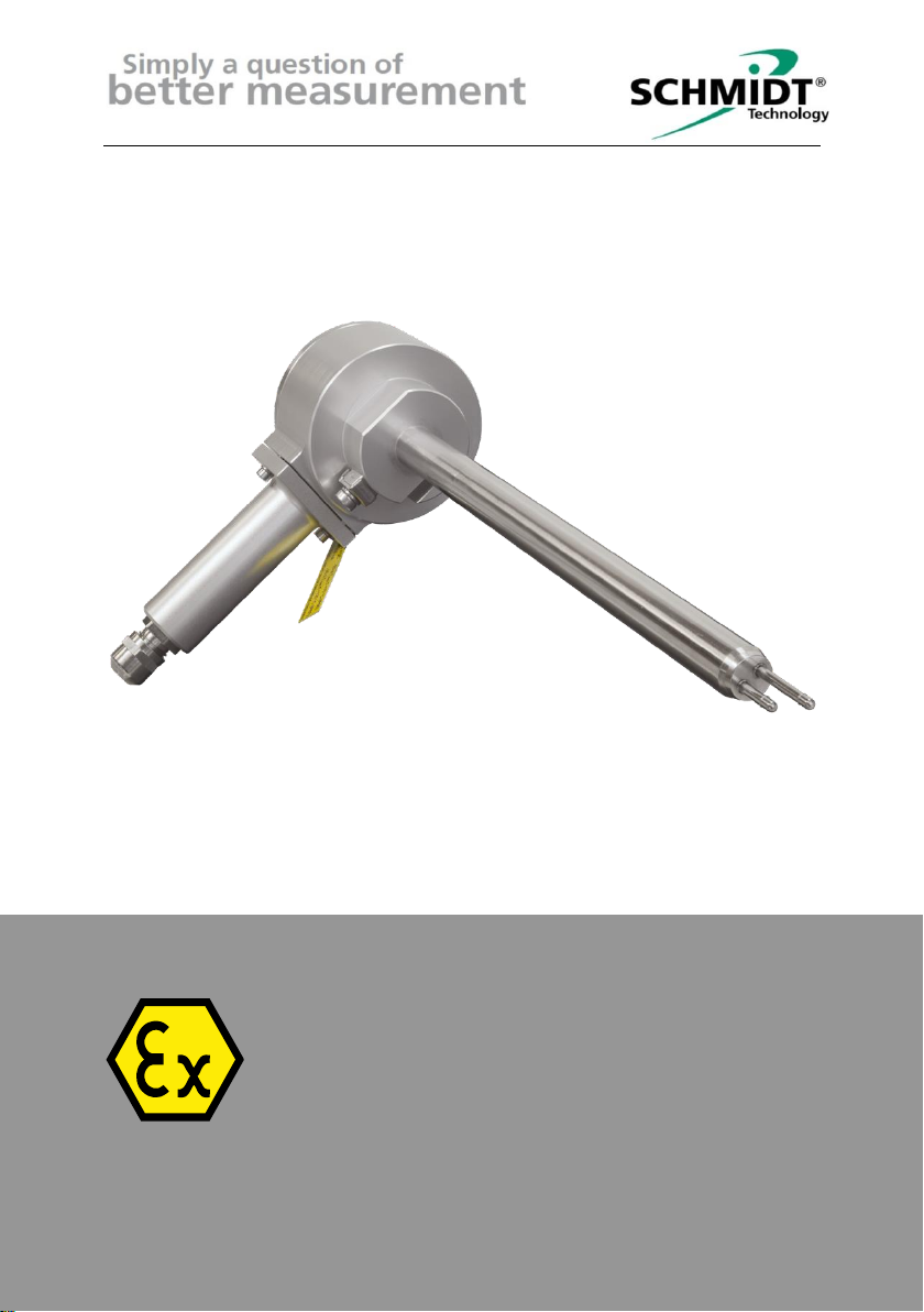
Mechanical versions
The sensor SS 23.700 Ex is available in two mechanical versions:
- Compact sensor:
The sensor probe is fixed to the main enclosure.
- Remote sensor:
The sensor probe is mechanically separated from the main enclosure.
Connection is realized by an electrical signal cable that cannot be de-
tached on either side.
The different construction types and their dimensions can be found in the
dimensional drawings in chapter 13.