Schmidt SS 20.261 User manual

SCHMIDT®Flow Sensor
SS 20.261
Instructions for Use

Instructions for Use SS 20.261 Page 2
SCHMIDT®Flow Sensor
SS 20.261
Table of Contents
1Important Information.......................................................................3
2Application range .............................................................................4
3Mounting instructions.......................................................................5
4Electrical connection......................................................................12
5Signalizations.................................................................................13
6Startup............................................................................................15
7Information concerning operation ..................................................15
8Service information ........................................................................17
9Technical data................................................................................18
10 EC Declaration of conformity.........................................................19
Imprint:
Copyright 2012 SCHMIDT Technology GmbH
All rights reserved
Version 527254.02B
Subject to modifications

Instructions for Use SS 20.261 Page 3
1 Important information
The instructions for use contain all required information for a fast
commissioning and a safe operation of the SCHMIDT®Flow sensor
SS 20.261:
These instructions for use must be read completely and observed
carefully, before putting the unit into operation.
Any claims under the manufacturer's liability for damage resulting
from non-observance or non-compliance with these instructions will
become void.
Tampering with the device in any way whatsoever - with the
exception of the designated use and the operations described in
these instructions for use - will forfeit any warranty and exclude any
liability.
The unit is designed exclusively for the use described below (see
chapter 2). In particular, it is not designed for direct or indirect
personal protection.
SCHMIDT Technology cannot give any warranty as to its suitability
for a certain purpose and cannot be held liable for accidental or
sequential damage in connection with the delivery, performance or
use of this unit.
Symbols used in this manual
The symbols used in this manual are explained in the following section.
!
Danger warnings and safety instructions –read them
carefully!
Non-observance of these instructions may lead to injury of
personnel or malfunction of the device.
General note
All dimensions are indicated in mm.

Instructions for Use SS 20.261 Page 4
2 Application range
The SCHMIDT®Flow sensor SS 20.261 is designed for stationary
measurement of the flow velocity as well as the temperature of air and
gases at working pressure of up to 10 bar.
The sensor is based on the measuring principle of the thermal
anemometer and measures the mass flow of the measuring medium as
flow velocity which is output in a linear way as standard velocity
1
wN
(unit: m/s), based on standard conditions of 1013.25 hPa and 20 °C.
Thus, the resulting output signal is independent from the pressure and
temperature of the medium to be measured.
The SS 20.261 is designed for the use inside closed rooms and is not
suitable for outdoor use.
1
Equates to the real flow velocity under standard conditions.

Instructions for Use SS 20.261 Page 5
3 Mounting instructions
General information on handling
The SS 20.261 is a precision instrument with high measuring sensitivity.
In spite of the robust construction of the sensor tip soiling of the inner
sensor elements can lead to distortion of measurement results (see also
chapter 8 Service information). During procedures that could stimulate
soiling like transport, mounting or dismounting of the sensor it is
recommended to place the enclosed SCHMIDT Technology protective
cap on the sensor tip and remove it only during operation.
!
During processes with enhanced risks of soiling such as
transport or mounting the protective cap should be placed onto
the sensor tip.
Systems with overpressure
The SS 20.261 is designed for a maximum working overpressure of
10 bar. As long as the medium to be measured is operated with
overpressure, make sure that:
There is no overpressure in the system during mounting.
!
Mounting and dismounting of the sensor in pipes can be
carried out only as long as the system is in depressurized
state.
Only appropriately pressure-tight mounting accessories are used.
!
Only use proper pressure-tight mounting accessories (e. g.
Teflon tape).
Appropriate safety precautions are taken to avoid unintended
discarding of the sensor due to overpressure.
!
Attention: Risk of injuring if through bolt joint is
loosened under pressure!
If there are leaks in the sensor or its compressing fitting (CF) during
operation, depressurize the system immediately and replace sensor.

Instructions for Use SS 20.261 Page 6
General installation conditions
Preferably the sensor should be mounted in horizontal pipes.
The sensor should preferably be installed in horizontally positioned
pipes. A downward flow with low flow speeds (< 1 m/s)
2
can lead to
increased deviations and must be avoided for this reason.
!
Avoid installation in a pipe or chamber with downward flow
because the lower measuring range limit can rise significantly.
The sensor measures the flow speed correctly only in the direction given
on the housing and sensor head (arrow). Make sure that the sensor is
adjusted in flow direction; a tilting of up to ±3° is allowed
3
.
!
The sensor measures unidirectional and must be adjusted
correctly relative to the flow direction.
A sensor mounted in opposite direction of the flow direction leads to
wrong measuring values (too high).
!
The lower measuring range limit is according to the system
requirements 0.2 m/s.
The center of the chamber head is the actual measuring point of the flow
measurement and must be placed in the flow as advantageous as
possible, for example in the middle of a pipe (see Figure 1). Therefore
this point is also used for specification of probe length L (see Figure 3).
Figure 1 Positioning in a pipe
!
The sensor head must be located in the center of the pipe to
obtain a correct measurement inside the pipe.
2
In case of vertical downdraft and maximum overpressure of 8 bar.
3
Measurement deviation < 1 %
Flow
Direction of measurement

Instructions for Use SS 20.261 Page 7
Installation with low disturbance
Local turbulences of the medium can cause distortion of measurement
results. Therefore, appropriate mounting conditions must be guaranteed
to ensure that the gas flow is supplied to the sensor in a quiet and low in
turbulence state in order to maintain the accuracy specified (see chapter
9 Technical data).
!
Correct measurements require quiet flow, as low-turbulence as
possible.
An undisturbed flow profile can be achieved if a sufficiently long distance
in front of (run-in distance) and behind (run-out distance) the sensor
installation site (see Figure 2) is held absolutely straight and without
disturbances (such as edges, seams, bends etc.). It is also necessary to
pay attention to the design of the run-out distance because disturbances
also generate turbulences against the flow direction.
L2
L
D
L1
L
= Length of entire measuring distance
L1
= Length of run-in distance
L2
= Length of run-out distance
D
= Inner diameter of measuring distance
Figure 2
The following Table 1 shows the required straight conduit lengths
depending on the pipe inner diameter “D” and the different disturbance
causes.
Flow obstacle upstream of the measuring
distance
Minimum
length of L1
Minimum
length of L2
Light bend (< 90°)
10 x D
5 x D
Reduction / expansion / 90° bend or T-junction
15 x D
5 x D
Two 90° bends in one plane (2-dimensional)
20 x D
5 x D
Two 90° bends (3-dimensional change in direction)
35 x D
5 x D
Shut-off valve
45 x D
5 x D
Table 1

Instructions for Use SS 20.261 Page 8
This table lists the minimum values required in each case. If the listed
straight conduit lengths cannot be achieved, measurement accuracy
may be impaired
4
.
Calculation of volume flow
If the cross section area of the pipe is known, the output signal of the
flow speed can be used to calculate the standard volumetric flow of the
medium. By means of a correction factor PF
5
, which depends on the
pipe diameter the measured value can be converted to an averaged flow
wNwhich is constant over the whole pipe cross-section.
Thus, it is possible to calculate the standard volumetric flow of the
medium using the measured standard flow velocity in a pipe with known
inner diameter:
EFAwV
wPFw
DA
NN
NN
2
4
The measuring unit factor EF serves only for convenient conversion to
non-SI measuring units, for example m3/h (see Table 2).
SCHMIDT Technology provides a convenient calculation tool to
compute flow velocity or volume flow in pipes for all its sensor types and
measuring ranges. This “Flow Calculator” can be directly used on or
downloaded from SCHMIDT homepage:
http://www.schmidttechnology.de/de/sensorik/download/FlowCalculator.zip
Measuring unit of diameter D
EF
m
cm
mm
Measuring unit
volumetric flow
m3/s
1
1,0E-04
1,0E-06
m3/min
60
6,0E-03
6,0E-05
m3/h
3600
3,6E-01
3,6E-03
l/s
1000
1,0E-01
1,0E-03
l/min
6,0E+04
6
0,06
l/h
3,6E+06
360
3,6
Table 2
4
Alternatively flow rectifier could be used, e.g. honeycomb ceramics.
5
Considers the parabolic flow profile and the sensor obstruction.
D
Inner diameter of pipe [m]
A
Cross-section area of pipe [m2]
N
w
Flow velocity in the middle of the pipe [m/s]
N
w
Average flow velocity in the pipe [m/s]
PF
Profile factor (for pipes with circular cross-sections)
EF
Measuring unit factor (conversion to non-SI units)
N
V
Standard volumetric flow [m³/s]

Instructions for Use SS 20.261 Page 9
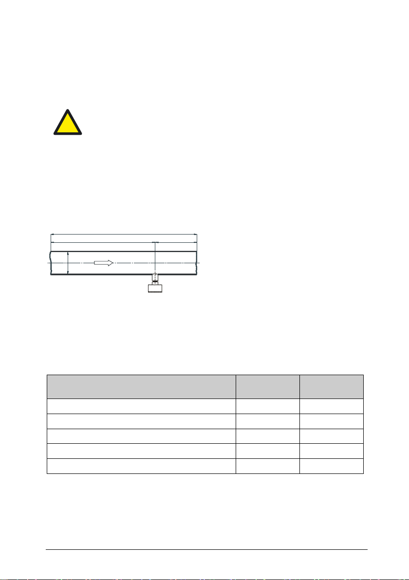
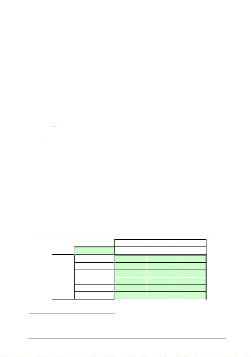
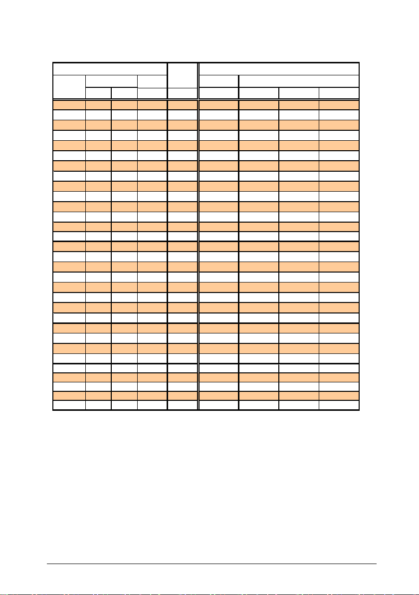
Table 3 lists profile factors and volume flow measuring ranges (with
certain sensor measuring ranges) for standard pipe diameters.
Table 3
Inner Min. @
DN [inch]
[mm] PF 0.2 m/s 40 m/s 60 m/s 90 m/s
25 25 126.0 0.796 0.30 61 91 137
28.5 0.796 0.37 73 110 165
32 32.8 0.796 0.48 97 145 218
1 1/4 36.3 0.770 0.57 115 172 258
40 40 1 1/2 39.3 0.748 0.65 131 196 294
43.1 0.757 0.80 159 239 358
45.8 0.763 0.91 181 272 407
50 50 251.2 0.772 1.14 229 343 515
54.5 0.775 1.30 260 391 586
57.5 0.777 1.45 291 436 654
64.2 0.782 1.82 365 547 820
65 65 2 1/2 70.3 0.786 2.20 439 659 988
76.1 0.792 2.59 519 778 1,167
80 80 382.5 0.797 3.07 614 920 1,380
100 100 4100.8 0.804 4.62 924 1,386 2,079
110 107.1 0.806 5.23 1,046 1,568 2,353
125 125 5125.0 0.812 7.17 1,435 2,152 3,229
130 125 131.7 0.814 7.98 1,597 2,395 3,593
150 150 6150.0 0.817 10.40 2,079 3,119 4,678
160 159.3 0.820 11.77 2,353 3,53 5,295
170 182.5 0.825 15.54 3,108 4,661 6,992
190 190.0 0.826 16.86 3,372 5,059 7,588
200 200 206.5 0.829 19.99 3,998 5,997 8,996
250 260.4 0.835 32.02 6,404 9,605 14,408
300 300 309.7 0.840 45.56 9,112 13,668 20,502
350 339.6 0.842 54.91 10,982 16,474 24,711
400 400 388.8 0.845 72.23 14,446 21,670 32,505
450 450 437.0 0.847 91.47 18,294 27,440 41,161
500 500 486.0 0.850 113.53 22,706 34,059 51,089
550 550 534.0 0.852 137.39 27,477 41,216 61,824
600 600 585.0 0.854 165.27 33,054 49,581 74,371
Nominal
size
Diameter of measuring pipe
Profile
faktor
Volumetric flow [m3/h]
Norm value
@ sensor measuring range [m/s]

Instructions for Use SS 20.261 Page 10
Mounting
The sensor is installed using its integrated compression fitting. Normally,
a sleeve is welded as a connecting piece onto a bore in the medium-
guiding pipe, in which the external thread (G½) of the compression fitting
is screwed (see Figure 3).
L
AL
66SL 32
MET=20
8 E
D
A
Figure 3
L
Probe length [mm]
SL
Length of weld-in sleeve [mm]
AL
Projecting length [mm]
DA
Outer diameter of pipe [mm]
MID
Minimum immersion depth [mm]
E
Setting length of probe [mm]
!
Before mounting depressurize system with overpressure media.
Bore a mounting opening in a pipe wall.
Weld connecting piece with an internal thread G½ in the center
above the mounting opening on the pipe.
Recommended length of connecting piece: 15 ... 40 mm
Slacken compression fitting nut (SW17) to such an extent that
sensor probe can be moved without jamming.
Wrap thread using a common sealing tape, for example made of
PTFE.
Remove protective cap from sensor tip and push compression fitting
up to the dead end of the sensor head.
MID = 20

Instructions for Use SS 20.261 Page 11
Screw threaded part of compression fitting one or two turns by hand
into connecting piece.
In case of a longer sensor probe push it partly into the pipe then
screw thread firmly into connecting piece (hexagon SW27).
!
Always avoid bending of the probe during screwing.
Carefully slide probe so that the center of the chamber head is
placed at the optimum measuring position in the middle of the pipe.
Tighten compression fitting nut slightly by hand so that sensor is
fixed.
Turn sensor manually at its enclosure into required direction and
precise position while maintaining immersion depth.
!
Angular deviation should not be greater than 3° relative to
ideal position.
Hold sensor and tighten compression fitting nut by turning the fork
wrench (SW17) a quarter of a turn.
Recommended torque: 10 … 15 Nm
Check the set angular position carefully, for example by means of a
spirit level at the hexagonal part of the sensor enclosure.
Make sure to close the safety chain before pressure is applied. The
chain lock must be hung up in a way to avoid sagging of the chain.
Figure 4: Safety chain

Instructions for Use SS 20.261 Page 12
Mounting accessories
Type / article No.
Drawing
Mounting
Clamp6
a.) 524 916
b.) 524 882
26,6
34
Rp 1/2
- Internal thread G½
- Material:
a.) Steel, black
b.) Stainless steel 1.4571
Table 4
4 Electrical connection
!
During electrical installation ensure that no voltage is applied
and inadvertent activation is not possible.
The sensor is electrically connected according to Table 5 by means of
the open cable ends of a 4-wire cable firmly fixed to the sensor housing.
Wire color
Designation
Function
Brown (BR)
Power
Operating voltage: +UB
White (WH)
GND
Operating voltage: Mass
Yellow (YE)
Analog wN
Output signal: Speed
Green (GR)
Analog TM
Output signal: Temperature of the medium
Table 5
Operating voltage
For proper operation the sensor requires DC voltage with a nominal
value of 24 V with permitted tolerance of ±10 % and the sensor is
protected against a polarity reversal.
Deviating values lead to deactivation of the measuring function or even
to failure. As far as it is possible, the LED indication as well as both
analog outputs report faulty operational conditions (see chapter 5
Signalization).
!
Only operate sensor within the defined range of operating
voltage (24 V DC ± 10 %). Undervoltage may result in
malfunction. Overvoltage may lead to irreversible damage to
the sensor.
6
Must be welded.

Instructions for Use SS 20.261 Page 13
Wiring of analog outputs
Both analog outputs signalizing flow and temperature of the medium are
designed as 4 … 20 mA current interface which exhibits permanent
short-circuit protection against both rails of the operating voltage UB.
RL
GR
WH
+
-
BR
A
CL
1µF UB+
Figure 5
The apparent ohmic resistance RLof max. 300 must be connected
between the signal output and GND (see Figure 5). Load capacity CLis
limited to a maximum of 10 nF.
5 Signalization
Light emitting diodes
The sensor is equipped with 2 light emitting diodes (LED) indicating its
functional state.
Operating state
LED 1
LED 2
Supply voltage too low
Ready for operation
Supply voltage too high
Medium temperature beyond specification range
Sensor defective
LED off
LED flashes (approx. 2 Hz): green
LED on: green
LED flashes (approx. 2 Hz): red
LED 1
LED 2
Flow

Instructions for Use SS 20.261 Page 14
Analog outputs
Error signaling
If a critical operating condition occurs or if the sensor detects a
defect, one or both interfaces emit 2 mA
7
.
Representation of the measuring range
The measuring range of the corresponding measuring value is
mapped in a linear way to the signaling range of its analog output.
For flow measurement the measuring range reaches from zero to the
selectable end of the measuring range wN,max (= 100 % in Figure 5).
A higher flow up to 22 mA (= 112,5 %) is still output in a linear way,
moreover the signal remains constant.
Flow velocity wN
Medium temperature TM
0112,5 wN [%]
020 40 8060 100
IOut
[mA]
20
4
22
12
8
16
IOut
[mA]
090
-40 T
M [°C]
20
4
8
20
22
40 + 8560-20
1212
16
2
)4(
16 ,
max, mAI
mA
w
wwNOut
N
N
CmAI
mA
C
TwNOutM
20)4(
16
105 ,
Figure 6 Representation specification for measuring functions
The measuring range of the medium temperature is -20 to +85 °C.
Falling below this temperature causes the emission of an error
message of this signal output (2 mA). An exceeded temperature is
output in a linear way up to 90 °C, moreover the temperature output
leaps to approx. 22 mA and the flow output drops to 2 mA.
!
Even short-term overshooting of the operating medium
temperature can cause irreversible damage of the sensor.
!
For a correct temperature measurement, the flow velocity
on the sensor head must be > 2 m/s. An excessive
temperature value is output if flow velocity is < 2 m/s.
7
In accordance with NAMUR specification.

Instructions for Use SS 20.261 Page 15
6 Startup
Prior to switching on the SCHMIDT®Flow sensor SS 20.261, the
following checks have to be carried out:
Immersion depth of the sensor probe and alignment of the housing
Tightening of the fastening screw of the through-bolt joint, correct
installation of safety chain
Correct electrical connection in the field (switch cabinet or similar)
!
For measurements in media with overpressure check if the
fastening screw is tightened properly (10 … 15 Nm). Make
sure to close the safety chain before pressure is applied.
5 seconds after switch-on the sensor is ready for operation. If the sensor
has another temperature than the ambient, this time is prolonged until
the sensor has reached its ambient temperature.
If the sensor has been stored at very cold conditions, before
commissioning you have to wait until the sensor and its housing have
reached ambient temperature.
7 Information concerning operation
The sensor is optimized for an operating overpressure of 8 barop. If it is
used with lower pressures, the detection limit (DL) rises slightly.
Example: DL (8 barop) = 0.2 m/s, DL (0 barop) = 0.8 m/s
!
Soiling or other gratings on the sensor cause distortions of
measurements.
Therefore, the sensor must be checked for soiling at regular
intervals and cleaned if necessary.
!
(Condensating) liquid on the sensor causes serious
measurement distortions.
After drying the correct measuring function is restored.

Instructions for Use SS 20.261 Page 16
Eliminating malfunctions
The following table lists possible errors (error images). A description of
the way to detect errors is given. Furthermore, the possible causes and
measures to be taken to eliminate errors are listed.
Error image
Possible causes
Troubleshooting
Problems with supply voltage UB:
No UBavailable
UBhas wrong polarity
UB< 15 V
Sensor defective
Sensor cable connected
correctly?
Supply voltage connected to
the control?
Supply cable broken?
Power supply unit large
enough?
IwN , ITM = 0 mA
Sensor element defective
Send the sensor for repair
IwN , ITM = 2 mA
Operating voltage too high
Medium temperature beyond
specification range
Check the operating voltage and
reduce it
Check the medium temperature
and set it correctly
IwN = 2 mA
ITM = 2 / 22 mA
Flow signal wNis
too large / small
Measuring range too small /large
Medium to be measured does not
correspond to air
Sensor element soiled
Sensor installed in opposite
direction to flow direction
Check sensor configuration
Check measuring resistance
Is the foreign gas factor correct?
Clean sensor tip
Check the installation direction
Flow signal wNis
fluctuating
UBunstable
Mounting conditions:
Sensor head is not in optimal
position
Run-in/run-out distance is too
short
Strong fluctuations of pressure or
temperature
Check the voltage supply
Check mounting conditions
Check operating parameters
Table 6

Instructions for Use SS 20.261 Page 17
8 Service information
Maintenance
Soiling of the sensor element may lead to a wrong measuring result. The
sensor tip must be checked regularly for soiling and must be cleaned
when required.
Cleaning of the sensor tip
The sensor tip can be cleaned to remove dust or soiling by moving it
carefully in warm water containing a washing-up liquid. If necessary a
soft brush can be used additionally.
!
Do not use strong cleaners, solvents, brush or other hard
objects.
Before putting it again into operation, wait until the sensor tip is
completely dry.
Transport / Shipment of the sensor
Before transport or shipment of the sensor, the delivered protective cap
must be placed onto the sensor tip. Avoid soiling or mechanical stress.
Recalibration
If the customer has made no other provisions, we recommend repeating
the calibration at a 12-month interval. To do so, the sensor must be sent
in to the manufacturer.
Spare parts or repair
No spare parts are available, since a repair is only possible at the
manufacturer's facilities. In case of defects the sensors must be sent in
to the producer for repair.
If the sensor is used in systems important for operation, we recommend
you to keep a replacement sensor in stock.
Test certificates and material certificates
Every new sensor is accompanied by a certificate of compliance
according to EN10204-2.1. Material certificates are not available.
Upon request, we shall prepare, at a charge, a factory calibration
certificate, traceable to national standards.

Instructions for Use SS 20.261 Page 18
9 Technical data
Measuring parameters
Standard velocity wNof air, based on standard conditions
20 °C and 1013.25 hPa
Medium temperature TM
Medium to be measured
Air or nitrogen, other gases on request
Measuring range wN
0 ... 40 / 60 / 90 m/s
Lower detection limit wN
0.2 m/s
Measuring accuracy wN
- Standard
- Precision*
±(5 % of measured value + 0.4 % of final value)
±(3 % of measured value + 0.4 % of final value)
Reproducibility wN
±1,5 % of measured value
Response time (t90 ) wN
3s (jump from 5 to 0 m/s)
Measuring range TM
-20 ... +85 °C
Measuring accuracy TM
±1 K (wN≥ 2 m/s)
Operating temperature
- Medium
- Electronics
-20 ... +85 °C
0 ... +70 °C
Humidity range
0 ... 95 % rel. humidity (RH), non-condensing
Operating overpressure
≤ 10 bar
Operating voltage UB
24 VDC ± 10 % (reverse voltage protected)
Current consumption
< 60 mA
Analog outputs
- Type
- RL
- CL
2 (short-circuit protected)
4 … 20 mA**
≤ 300
≤ 10 nF
Electrical connection
Cable fixed on housing, 4-pin, length 2 m, pigtail***
Line length
100 m max.
Protection class****
III (PELV)
Type of protection
IP 54 (enclosure)
IP 67 (sensor)
Mounting
Compression fitting G1/2 (integrated)
Mounting tolerance
±3° (relative to flow direction)
Installation length
200 / 350 mm
Weight
250 g max.
Table 7
*Under alignment conditions and with regard to the reproducibility of the reference.
** Error messaging: 2 mA; exceeding measuring range: up to 22 mA
*** With cable end sleeves
**** According EN 50178

Instructions for Use SS 20.261 Page 19
10 EC Declaration of conformity

Instructions for Use SS 20.261 Page 20
SCHMIDT Technology GmbH
Feldbergstrasse 1
78112 St. Georgen / Germany
Phone +49 (0)7724 / 899-0
Fax +49 (0)7724 / 899-101
info@schmidttechnology.de
www.schmidttechnology.de
Table of contents
Other Schmidt Accessories manuals

Schmidt
Schmidt SS 20.600 Ex Wiring diagram

Schmidt
Schmidt SS 20.260 User manual

Schmidt
Schmidt SS 20.500 User manual

Schmidt
Schmidt SS 20.600 User manual

Schmidt
Schmidt SS 20.600 User manual

Schmidt
Schmidt SS 20.651 User manual

Schmidt
Schmidt SS 20.515 LED User manual

Schmidt
Schmidt SS 23.700 Ex User manual

Schmidt
Schmidt SS 20.700 User manual

Schmidt
Schmidt SS 20.600 User manual
Popular Accessories manuals by other brands

Siemens
Siemens Milltronics RBSS instruction manual

Chamberlain
Chamberlain THE PROTECTOR SYSTEM 916GA user manual

Thermo Scientific
Thermo Scientific RMI300S-9-A Operating and maintenance manual

AND
AND Weighing Indicator AD-4324 instruction manual

The M
The M MEIDJO 2.0 quick start guide

Jabra
Jabra Elite Sport quick start guide