Schmidt SS 20.60 User manual

SCHMIDT®Flow Sensor
SS 20.60
Instructions for Use

Instructions for Use SS 20.60 Page 2/16
SCHMIDT®Flow Sensor
SS 20.60
Table of Contents
1Important Information....................................................3
2Range of Applications...................................................3
3Safety information.........................................................4
4Determination of the position of installation...................5
5Mounting instructions....................................................8
6Electrical connections ...................................................9
7Startup.........................................................................10
7.1 LED display ................................................................10
7.2 Error signaling ............................................................12
8Service information .....................................................13
9Declaration of conformity.............................................15
Imprint:
Copyright 2003 SCHMIDT Technology GmbH
All rights reserved.
Printed in the Federal Republic of Germany
Version: 300754.02B

Instructions for Use SS 20.60 Page 3/16
1 Important Information
These instructions for use must be read completely and observed
carefully, before putting the unit into operation.
Any claims under the manufacturer's liability for damage resulting
from non-observance or non-compliance with these instructions
will become void.
Tampering with the device in any way whatsoever - with the
exception of the designated use and the operations described in
these instructions for use - will forfeit any warranty and exclude
any liability.
The unit is designed exclusively for the use described below (s.
chapter 2 Range of Applications) In particular, it is not designed
for direct or indirect personal protection.
SCHMIDT Technology cannot give any warranty as to its
suitability for a certain purpose and cannot be held liable for errors
contained in these instructions for use or for accidental or
sequential damage in connection with the delivery, performance
or use of this unit.
2 Range of Applications
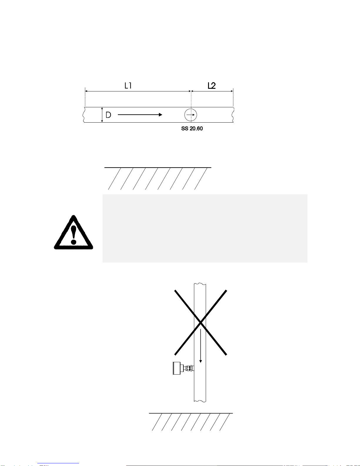
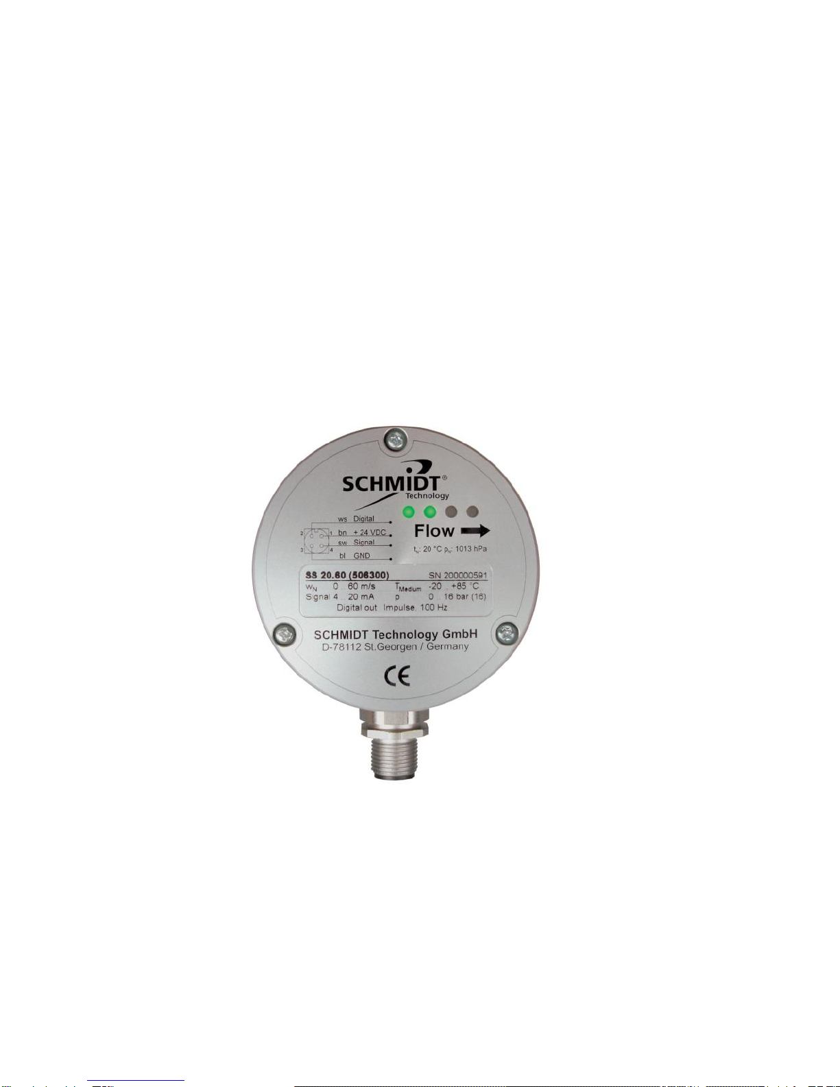
The SCHMIDT®flow sensor SS 20.60 is designed for stationary
use in compressed air pipes, air ducts or air shafts under
atmospheric pressure conditions. The sensor measures the flow
velocity of the measuring medium as standard velocity (unit m/s),
relative to the standard pressure of 1013.25 hPa and the standard
temperature of 20°C. The output signal is linear and independent
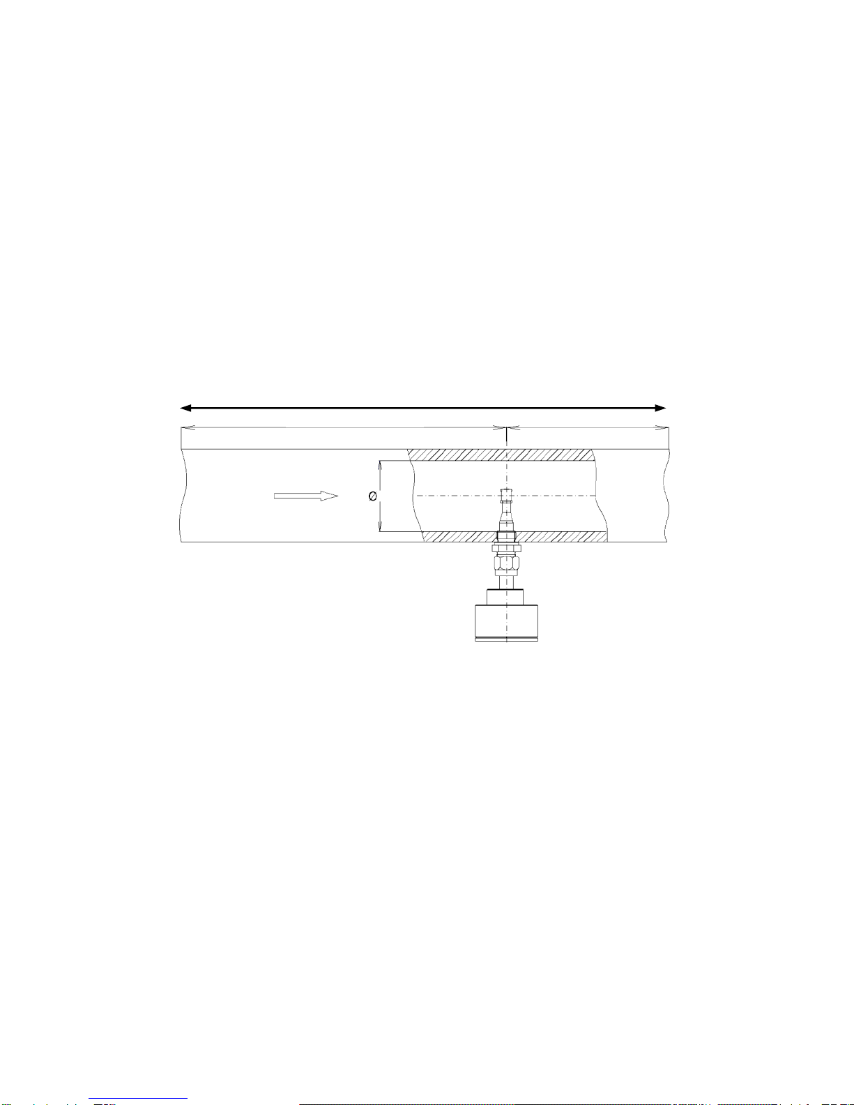
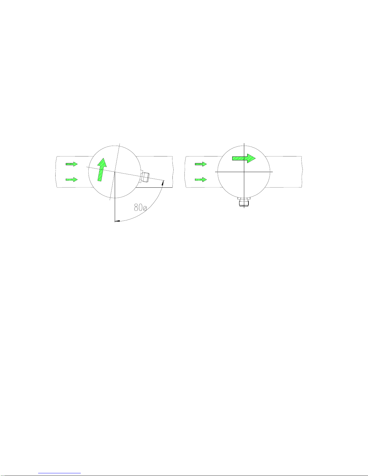
of the pressure and temperature of the medium. When mounting
the sensor in a tube, the output signal of the flow velocity can be
used to calculate the standard volumetric flow or the mass flow of
the medium. Please refer to the separate table “SS 20.60 Profile
Factors”.
When using the sensor outdoors, it must be protected against
direct ex-posure to the weather.

Instructions for Use SS 20.60 Page 4/16
3 Safety information
When installing and removing the sensor, it is essential to
observe the instructions detailed below:
1. The sensor may only be installed and removed when no
pressure is applied.
2. The nut (AF24) of the screw pipe connection must be firmly
tightened before applying compressed air.
Permitted tightening torque: 20 Nm minimum
30 Nm maximum
3. In case of mechanical strain (vibration), the nut (AF24) must be
secured additionally
(e.g. using a commercially available screw lock).
4. Make sure to close the safety chain before pressure is applied.
The chain lock must be hung up in a way to avoid sagging of
the chain.
ATTENTION
The maximum allowed positive operating
pressure of 16 bar must not be exceeded!
If the above safety instructions are not observed,
the sensor in the screw pipe connection may be
loosened and thrown out due to the
overpressure.

Instructions for Use SS 20.60 Page 5/16
4 Determination of the position of installation
To reach the accuracy specified in the data sheets, the sensor
has to be positioned in a straight conduit and at a place with
undisturbed flow profile. An undisturbed flow profile can be
achieved if a sufficiently long distance in front of the sensor (run-in
distance) and behind the sensor (run-out distance) is held
absolutely straight and without disturbances (such as edges,
seams, bends, etc.).
The design of the run-out distance is also important, since
disturbances do not only act in the direction of the air flow but also
lead to turbulence opposite to the flow direction.
run-in distance L1
run-out distance L2
D
Figure 1: Sensor position in the pipe
L= total length of the measuring distance, L1 = length of the run-in
distance, L2 = length of the run-out distance, D = diameter of the
measuring distance
The sensor tip must be positioned in the center of the pipe
opening as shown in Figure 1.
The following table shows the necessary straight conduit lengths
as a function of each disturbance.
L

Instructions for Use SS 20.60 Page 6/16
Table of run-in and run-out distances
Flow obstacle upstream
of the measuring conduit
Minimum length of
the run-in distance
(L1)
Minimum length of
the run-out
distance (L2)
Light bend (< 90°)
10 x D
5 x D
Contraction (conduit
contracts toward the
measuring area)
15 x D
5 x D
Expansion (conduit
expands toward the
measuring area)
15 x D
5 x D
90° bend or T-junction
15 x D
5 x D
Two 90° bends in one
plane
20 x D
5 x D
Two 90° bends with 3-
dimensional change in
direction
35 x D
5 x D
Shut-off valve
45 x D
5 x D
Table 1: Run-in and run-out distances
This table lists the minimum values required in each case. If the
listed straight conduit lengths cannot be achieved, the
measurement accuracy may be impaired.

Instructions for Use SS 20.60 Page 7/16
Installation position
The sensor should preferably be installed in horizontally
positioned pipes.
ATTENTION
Avoid installing the sensor in a pipe with downward
flow.
This would considerably increase the lower
measuring range limit.

Instructions for Use SS 20.60 Page 8/16
5 Mounting instructions
The safety instructions must be observed.
1. To install the sensor, first insert the through bolt joint into the
pipe union. Then introduce the sensor up to the desired
immersion depth and turn it, while it is still loose,
counter-clockwise by about 80°. Use a fork wrench (AF 27) to fix
the hexagon bolt at the screw pipe connection by a locknut.
Figure 2: Fixing the sensor in the pipe
2. Tighten the union nut (AF24) until the arrow on the sensor
housing corresponds to the direction of the pipe flow. The angular
deviation should not be greater than 3° referenced to the ideal
position. Otherwise the measurement accuracy may be affected.
You can check the set angular position by placing a bubble level
on the stop face. In case of wrong adjustment, the through bolt
joint has to be loosened. Repeat the mounting procedure as
described under item 1.
3. Make sure to close the safety chain before pressure is applied.
The chain lock must be hung up in a way to avoid sagging of the
chain.

Instructions for Use SS 20.60 Page 9/16
ATTENTION
The stop face of the housing must not be used
for securing.
The housing must not be turned any more,
once the through bolt joint has been tightened.
Otherwise, the housing may be detached from
the sensor tube.
6 Electrical connections
1
4
3
2bn
sw
bl
+ 24 VDC
Signal
GND
ws Digital
Figure 3: SS 20.60 connection assignment (view of the plug pins at
the sensor)
The cable supplied has the following color assignment:
ws = white, bn = brown, sw = black, bl = blue
The negative of the dc voltage (GND) is at the same time the
reference potential for the analog signal.
ATTENTION
Only operate the sensor in the defined range of
operating voltage (24 VDC +/- 20 %).
Undervoltage may result in malfunction.
Overvoltage may lead to irreversible damage to
the sensor.

Instructions for Use SS 20.60 Page 10/16
7 Startup
The valid measuring range and the configuration of the signal
outputs are specified on the rating plate (see housing cover).
Note: After applying the supply voltage, the output signal will at
first adopt a higher value and then level off at the correct
measurement value after about 10 seconds.
7.1 LED display
The sensor has 4 LEDs indicating its current state.

Instructions for Use SS 20.60 Page 11/16
The following table indicates the different signaling options:
No.
State
LED
1
LED
2
LED
3
LED
4
1
Ready for operation & flow < 5%
2
Flow > 5%
3
Flow > 20%
4
Flow > 50%
5
Flow > 80%
6
Flow > 100% = overflow
7
Sensor element defective
8
Operating voltage too low
9
Operating voltage too high
10
Electronic temperature too high
11
Electronic temperature too low
Table 2: Sensor state signaling
LED off
LED on: green
LED on: orange
LED flashes (approx. 2Hz): red

Instructions for Use SS 20.60 Page 12/16
7.2 Error signaling
In case of malfunction of the sensor element, all the four LEDs
flash in red (also see Table 2: Sensor state signaling) and the
output variant 4 ... 20 mA generates a current of 2 mA.
In this case, the device must be sent to the manufacturer for
repair.
The other error states signaled by the LEDs are not indicated at
the analog output. LED signaling remains active until the cause of
the error has been eliminated.
ATTENTION
Causes of any error signaling have to be
eliminated immediately. A significant exceeding
or falling below the permitted operating
parameters can result in permanent damage to
the sensor.
ATTENTION
During error state signaling, the measured
values at the analog output may show
considerable deviations.

Instructions for Use SS 20.60 Page 13/16
8 Service information
Maintenance
The sensor tip must be checked regularly for contamination and
must be cleaned when required. Contamination of the sensor
element may lead to a false measurement. It is recommended to
check it once a year and more frequently if it is heavily
contaminated.
Cleaning the sensor tip
The sensor tip can be cleaned to remove dust/dirt by moving it
carefully in warm water containing (a) washing-up liquid; if
necessary a very soft brush can be used. Before putting it back
into operation, wait until the sensor tip is completely dry.
ATTENTION
Do not use strong cleaners, solvents, brush or
other hard objects.
Recalibration
If the customer has made no other provisions, we recommend
repeating the calibration at a 12-month interval. To do so, the
sensor must be sent in to the manufacturer.

Instructions for Use SS 20.60 Page 14/16
Spare parts or repair
No spare parts are available, since a repair is only possible at the
manufacturer. In case of defects, the parts must be sent in to the
supplier for repair.
When the sensor is used in systems important for operation, we
recommend keeping a replacement sensor in stock.
Test certificates
Upon request, we shall prepare, at a charge, a factory calibration
certificate, traceable to national standards.

Instructions for Use SS 20.60 Page 15/16
9 Declaration of conformity

Instructions for Use SS 20.60 Page 16/16
SCHMIDT Technology GmbH
Feldbergstrasse 1
D-78112 St. Georgen
Phone +49 (0)7724/899-0
Fax +49 (0)7724/899-101
info@schmidttechnology.de
www.schmidttechnology.de
Table of contents
Other Schmidt Accessories manuals

Schmidt
Schmidt SS 23.700 Ex User manual

Schmidt
Schmidt SS 20.260 User manual

Schmidt
Schmidt SS 20.515 LED User manual

Schmidt
Schmidt SS 20.500 Ex User manual

Schmidt
Schmidt SS 20.700 User manual

Schmidt
Schmidt SS 23.400 ATEX 3 User manual

Schmidt
Schmidt SS 20.261 User manual

Schmidt
Schmidt SS 20.225 User manual

Schmidt
Schmidt SS 20.501 User manual

Schmidt
Schmidt SS 20.260 User manual
Popular Accessories manuals by other brands

Bosch
Bosch GHJ 12+18V Unisex Original instructions

Lucky Reptile
Lucky Reptile Thermo Socket plus Reflector operating instructions

NORAUTO
NORAUTO 2398784 manual

Masimo
Masimo M-LNCS Series manual

LEGRAND
LEGRAND Wattstopper FSP-211 installation instructions

Eaton
Eaton CurrentWatch EGF Series Instruction leaflet