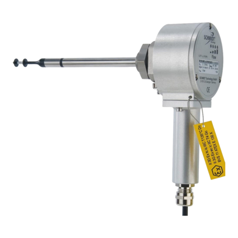
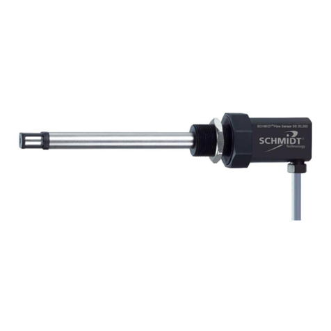
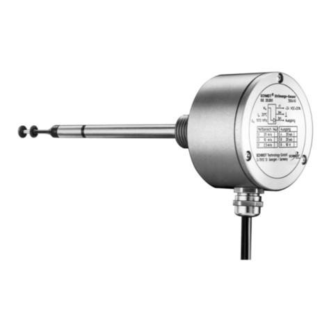
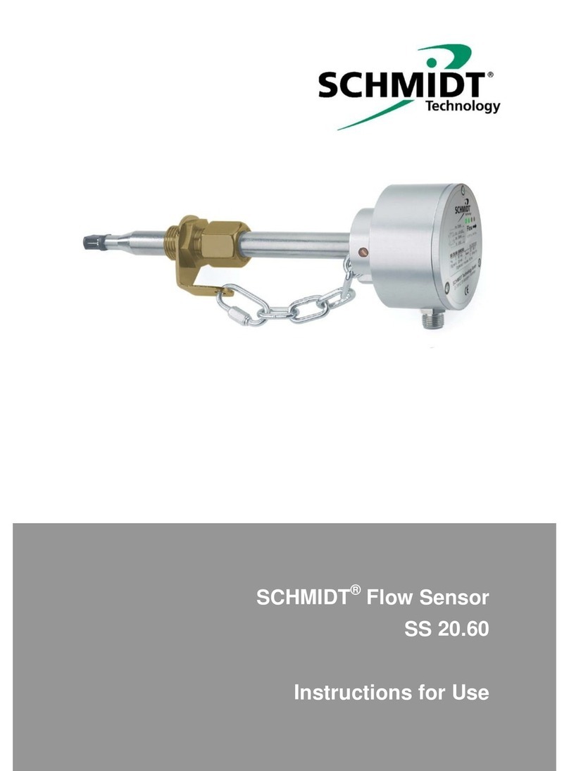
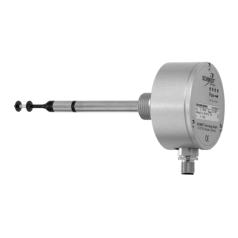
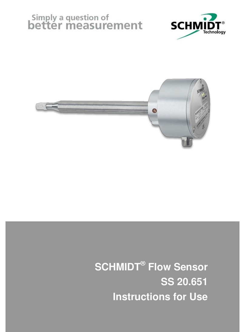
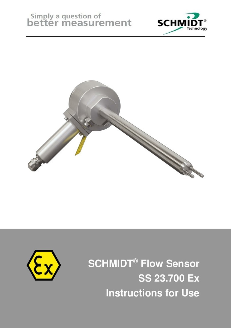
Schmidt SS 20.700 User manual

SCHMIDT®Flow Sensor
SS 20.700
Instructions for Use

Instructions for Use –SCHMIDT®Flow Sensor SS 20.700 Page 2
SCHMIDT®Flow Sensor SS 20.700
Table of Contents
1Important information.......................................................................3
2Application range.............................................................................4
3Mounting instructions.......................................................................6
4Electrical connection......................................................................17
5Signaling........................................................................................22
6Commissioning..............................................................................28
7Information concerning operation..................................................28
8Service information........................................................................29
9Dimensions....................................................................................32
10 Technical data ...............................................................................33
11 Declarations of conformity.............................................................35
Imprint:
Copyright 2022 SCHMIDT Technology GmbH
All rights reserved
Version: 568365.02
Subject to modifications

Instructions for Use –SCHMIDT®Flow Sensor SS 20.700 Page 3
1 Important information
The instructions for use contain all required information for a fast commis-
sioning and a safe operation of SCHMIDT®flow sensors.
These instructions for use must be read completely and observed care-
fully, before putting the unit into operation.
Any claims under the manufacturer's liability for damage resulting from
non-observance or non-compliance with these instructions will become
void.
Tampering with the device in any way whatsoever - with the exception
of the designated use and the operations described in these instruc-
tions for use - will forfeit any warranty and exclude any liability.
The unit is designed exclusively for the use described below (refer to
chapter 2). In particular, it is not designed for direct or indirect protec-
tion of personal or machinery.
SCHMIDT Technology cannot give any warranty as to its suitability for
a certain purpose and cannot be held liable for errors contained in
these instructions for use or for accidental or sequential damage in
connection with the delivery, performance or use of this unit.
Symbols used in this manual
The symbols used in this manual are explained in the following section.
Danger warnings and safety instructions. Read carefully!
Non-observance of these instructions may lead to injury of per-
sonal or malfunction of the device.
General note
All dimensions are given in mm.

Instructions for Use –SCHMIDT®Flow Sensor SS 20.700 Page 4
2 Application range
The SCHMIDT®Flow Sensor SS 20.700 (art. no.: 562 140) is designed
for stationary measurement of the flow velocity as well as the temperature
of air and gas with operating temperature from -20 … +120 °C and working
pressure
1
up to 16 bar.
The sensor is based on the measuring principle of a thermal anemometer
and measures the mass flow of the measuring medium as flow velocity
which is output in a linear way as standard velocity
2
wN(unit: m/s), based
on standard conditions of 1013.25 hPa and 20 °C. Thus, the resulting out-
put signal is independent of the pressure and temperature of the medium
to be measured.
When using the sensor outdoors, it must be protected against di-
rect exposure to the weather.
Versions „Oxygen (O2) > 21 %“ and
„Grease-free and Oxygen (O2) > 21 % (PWIS-free)“
The variant "Oxygen (O2) > 21 %", which is suitable for use in concen-
trated oxygen, differs constructively from the standard version only by
the use of a special compression fitting. Its sealing O-ring consists of
BAM
3
-approved FKM which is coated with an oxygen-suitable lubri-
cant.
The variant “Grease-free and Oxygen (O2) > 21 % (PWIS-free)”is also
suitable for the use in concentrated oxygen but in addition its com-
pletely free of any lubricant. Aside from that the seal of the compres-
sion fitting is realized with a clamping ring made of stainless steel thus
there are no synthetics which comes in contact with the medium. The
sensor can also be used in applications where paint-wetting impair-
ment substances (PWIS) are not acceptable.
The sensor, its accessories and the packaging have been cleaned espe-
cially according to the standard IEC/TR 60877:1999.
This standard restricts the use of the sensor to biatomic oxygen O2(small
residual amounts of ozone are acceptable nevertheless).
Improper handling of gas mixtures with an oxygen content of more
than 21 % or pure oxygen can lead to fires or explosions.
1
Overpressure
2
Corresponds to the actual velocity under standard conditions
3
BAM: Bundesanstalt für Materialforschung und –prüfung (german federal authority)

Instructions for Use –SCHMIDT®Flow Sensor SS 20.700 Page 5
It is explicitly pointed out that the customer, by opening the pack-
aging, assumes full responsibility for the cleanliness of both the
sensor as well as its accessories according to the standard
IEC/TR 60877:1999.
Information concerning O2compliant handling
The general rule is that a soiling of sensor parts that come into contact
with oxygen must be absolutely avoided:
- The installation site must be carefully cleaned before mounting of the
sensor.
- Make sure to use only clean tools and material for the installation.
- Before opening the packaging film, remove the dirt such as dust from
the film, if necessary.
- If possible, open the packaging film and take out the sensor directly at
the installation site.
- Otherwise open the packaging film at an appropriate and clean work-
place and store the sensor in an appropriate, cleaned, dust- and humid-
ity-tight container.
- Do not touch the oxygen contacting sensor parts with bare hands.
- Use clean and non-fluffy gloves or cloths or similar to handle the sensor.
Version for “special gases”
The version of the SS 20.700 for “special gases” receives a gas-specific
adaption for the measurement of certain gases and gas mixtures.
The sensor is adjusted and calibrated in air. Then a special correction
function for the medium to be measured is applied to the sensor. This cor-
rection has been determined for many gases in real gas ducts. For gas
mixtures, the correction adaption is calculated according to the set volumic
mixing ratio.
Mechanical versions
The sensor SS 20.700 is available in two versions:
- Compact sensor:
The sensor probe is fixed to the main enclosure.
- Remote sensor:
The sensor probe is mechanically separated from the main enclosure.
Connection is realized by an electrical signal cable that cannot be de-
tached on either side.
The different construction types an their dimensions can be found in the
dimensional drawings in chapter 9.
The customer is responsible for observing all relevant statutory
provisions, standards and directives relating to the use of gases.

Instructions for Use –SCHMIDT®Flow Sensor SS 20.700 Page 6
3 Mounting instructions
General information on handling
The flow sensor SS 20.700 is a precision instrument with high measuring
sensitivity. In spite of the robust construction of the sensor head, soiling of
the sensor elements can lead to distortion of measurement results (see
also chapter 8).
During procedures such as transport, installation or dismounting of the
sensor that facilitates soiling as well as represent a mechanical load on
the sensor head, it is generally necessary to attach the enclosed protec-
tive cap of SCHMIDT Technology to the sensor head and remove it only
during operation.
To avoid soiling and mechanical stress on the sensor head, the
protective cap should be placed over it during transport or instal-
lation.
Mounting method
The sensor SS 20.700 can be mounted only by means of a compression
fitting which supports the sensor tube and ensures frictional clamping. The
compression fitting as well as a pressure protection kit is included in the
scope of delivery.
Due to the variety of applications the compression fitting exists in different
versions. On the one hand they are determined by the design of the ex-
ternal thread (order option: G½ or R½), on the other hand by the materials
and properties of the sealing:
Standard: O-Ring (NBR)
Oxygen (O2): O-Ring (FKM, BAM approved)
Grease-free: Clamping ring (stainless steel)
Systems with overpressure
The SS 20.700 is designed for a maximum working pressure of 16 bar.
As long as the medium to be measured is operated with overpressure,
make sure that:
There is no overpressure in the system during mounting.
Mounting and dismounting of the sensor can be carried out
only as long as the system is in a depressurized state.
Only suitable pressure-tight mounting accessories are used.
Appropriate safety measures are installed to avoid unintended discard-
ing of the sensor due to overpressure. If other accessories than the
delivered pressure protection kit or alternative mounting solutions are
used, the customer must ensure the corresponding safety measures.

Instructions for Use –SCHMIDT®Flow Sensor SS 20.700 Page 7
For measurements in media with overpressure, appropriate
safety measures must be taken to prevent unintended discard-
ing of the sensor.
The pressure-tight mounting, the fastening of the screw pipe
connection and the discarding protection must be checked be-
fore pressure is applied. These tightness checks must be re-
peated at reasonable intervals.
The components of the pressure protection kit (bolt, chain and
bracket) have to be checked regularly for integrity.
Thermal boundary conditions
In the case of medium temperatures that don’t correspond to the permis-
sible operating temperature of the electronics, cross-talk of the tempera-
ture into the electronics housing must be prevented by a thermal decou-
pling section of the sensor tube having a free-standing length of at least
50 mm (see Figure 3-1) or by means of other suitable measures.
Figure 3-1
The permissible operating temperature range of the electronics
must not be exceeded by crosstalk of the medium temperature on
the sensor housing.
Flow characteristics
Local turbulences of the medium can cause distortion of measurement
results. Therefore, appropriate mounting conditions must be guaranteed
to ensure that the gas flow is supplied to the sensor in a laminar
4
state,
i.e. quiet and low in turbulence. The corresponding measures depend on
the system properties (pipe, chamber, etc.) which are described in the fol-
lowing subchapters for different mounting variants.
Correct measurements require a(laminar) flow, low in turbulence.
4
The term “laminar” means here an air flow, low in turbulence (not according to its physical
definition saying that the Reynolds number is < 2300).
> 50 mm
2

Instructions for Use –SCHMIDT®Flow Sensor SS 20.700 Page 8
General installation conditions
The sensor head of the SS 20.700 consists of two basic elements:
Heater
The longer of the two sensor tubes at the tip of the sensor head is the
so-called heater. It consists of a heated, temperature-dependent resis-
tor that is used to measure flow velocity.
The end of the heater element, to which the length specification (L) of
the sensor also refers, represents the actual measuring point of the
flow measurement and should be placed as favourably as possible in
the flow, e.g. in the middle of the pipe.
Temperature sensing element
The shorter of the two sensor tubes at the tip of the sensor head is the
temperature sensor. It consists of an unheated, temperature-depend-
ent resistor, which measures the temperature of the medium.
The aerodynamically optimized design allows tilting around the longitudi-
nal axis of the sensor up to ±3° relative to the ideal measuring direction
(see Figure 3-2) without significant impact on the measurement result
5
.
The axial tilting of the sensor head relative to the flow direction
should not exceed ±3°.
Position the sensor head always at the most advantageous posi-
tion for flow measurement.
The sensor measures unidirectional (see “flow arrow” in Figure
3-2) and must be adjusted correctly relative to the flow direction.
View on probe head View on enclosure cover
Figure 3-2 Alignment of sensor to flow direction
5
Deviation < 1 % of the measured value
Alignment plane

Instructions for Use –SCHMIDT®Flow Sensor SS 20.700 Page 9
Mounting in pipes with circular cross-section
Typical applications for this type are compressed air networks or burner
gas supply lines. They are characterized by long thin pipes with a typically
quasi-parabolic flow profile.
The easiest method to achieve a low-turbulence flow is to provide a suffi-
ciently long and absolutely straight distance without disturbances (such as
edges, seams, bends etc.) in front (inlet) and behind the sensor (outlet)
(see installation drawing Figure 3-3). It is also necessary to pay attention
to the design of the outlet distance because the flow is also influenced by
disturbances generating turbulences against the flow direction.
Figure 3-3
L1
Length of run-in distance
L2
Length of run-out distance
D
Inner diameter of measuring distance
The absolute length of the corresponding distances is defined by the inner
diameter of the pipe because the flow abatement depends directly on the
aspect ratio of measuring distance and diameter. Therefore, the required
abatement distances are specified as a multiple of the inner pipe diameter
D. Besides, the degree of turbulence generation by the corresponding dis-
turbing object plays an important role. A slightly curved bend directs the
air with a relative low-disturbance level, whereas a valve generates mas-
sive turbulences with its abrupt change of the flow-guiding cross-section,
requiring a relatively long distance for abatement.
The following Table 1 shows the required straight pipe lengths depending
on the inner tube diameter D and different causes of disturbances.
This table lists the minimum values required in each case. If the listed
straight pipe lengths cannot be achieved, measurement accuracy may be
impaired or additional actions are required like the use of flow rectifiers
6
.
6
E.g., honeycombs made of plastic or ceramics.
Run-in distance L1
Run-out distance L2
Ø D

Instructions for Use –SCHMIDT®Flow Sensor SS 20.700 Page 10
Flow obstacle upstream of measuring distance
Minimum distance length of
Run-in (L1)
Run-out (L2)
Light bend (< 90°)
10 x D
5 x D
Reduction
expansion
90° bend
T-junction
15 x D
5 x D
Two 90° bends in
one plane
(2-dimensional)
20 x D
5 x D
Two 90° bends
with 3-dimensional
change in direction
35 x D
5 x D
Shut-off valve
45 x D
5 x D
Table 1 Run-in and run-out distances
The profile factors specified in Table 2 may become void by the use of
flow rectifiers.

Instructions for Use –SCHMIDT®Flow Sensor SS 20.700 Page 11
Calculation of volume flow
A quasi-parabolic speed profile is formed over the pipe’s cross-section
under laminar conditions. Whereas the flow velocity at the pipe walls re-
mains almost zero, in the middle of the pipe it reaches the optimum meas-
uring point, its maximum wN. This measured variable can be converted
into an average flow velocity
N
w
that is constant over the pipe cross-sec-
tion with the aid of a correction factor the so-called profile factor PF.
The profile factor depends on the inner pipe diameter
7
(see Table 2).
PF
Pipe Ø
Volume flow [m3/h]
Inner
Outer
Min. @
@ Sensor measuring range
[mm]
[mm]
0.2 m/s
10 m/s
20 m/s
60 m/s
90 m/s
140 m/s
220 m/s
0.748
39.3
44.5
0.7
32.7
65.3
196.0
294.0
457.3
718.6
0.772
51.2
57.0
1.1
57.2
114.4
343.3
515.0
801.1
1258
0.786
70.3
76.1
2.2
109.8
219.7
659.0
988.5
1537
2416
0.797
82.5
88.9
3.1
153.4
306.8
920.3
1380
2147
3374
0.804
100.8
108.0
4.6
231.0
462.0
1385
2078
3233
5081
0.812
125.0
133.0
7.2
358.7
717.5
2152
3228
5022
7892
0.817
150.0
159.0
10.4
519.8
1039
3118
4677
7276
11434
0.829
206.5
219.1
20.0
999.5
1999
5997
8995
13993
21989
0.835
260.4
273.0
32.0
1700
3201
9605
14408
22412
35219
0.840
309.7
323.9
45.6
2278
4556
13668
20502
31892
50116
0.841
339.6
345.6
54.8
2742
5484
16454
24681
38393
60331
0.845
388.8
406.4
72.2
3611
7223
21669
32504
50562
79455
0.847
437.0
457.0
91.5
4573
9146
27440
41160
64027
100614
0.850
486.0
508.0
113.5
5676
11353
34059
51088
79471
124883
0.852
534.0
559.0
137.4
6869
13738
41216
61824
96170
151125
0.854
585.0
610.0
165.3
8263
16526
49580
74371
115688
181796
0.860
800.0
311.2
15562
31124
93373
140059
217870
342368
0.864
1000
488.6
24429
48858
146574
219861
342006
537438
0.872
1500
1109
55474
110948
332845
499268
776639
1220433
0.877
2000
1983
99186
198372
595118
892677
1388609
2182100
Table 2 Profile factors and volume flows of different pipe diameters
7
Both inner air friction and sensor locking are responsible.

Instructions for Use –SCHMIDT®Flow Sensor SS 20.700 Page 12
Thus, it is possible to calculate the standard volume flow of the medium
using the measured standard flow velocity in a pipe with known inner di-
ameter:
AwV
wPFw
DA
NN
NN
2
4
D
Inner diameter of pipe [m]
A
Cross-section area of pipe [m2]
N
w
Flow velocity in the middle of the pipe [m/s]
N
w
Average flow velocity in the pipe [m/s]
PF
Profile factor (for pipes with a circular cross-section)
N
V
Standard volume flow [m3/s]
SCHMIDT Technology provides a "flow calculator" on its homepage for
the calculation of flow velocity or volume flow in (circular) pipes or (rectan-
gular) ducts for the different sensor types:
www.schmidt-sensors.com or www.schmidttechnology.de
Installation in systems with square cross-section
For most applications, two limit cases can be distinguished with regard to
flow conditions:
Quasi-uniform flow field
The lateral dimensions of the flow-guiding system are approximately as
large as its length in the flow direction and the flow velocity is small so
that a stable trapezoidal
8
speed profile of the flow is formed. The width
of the flow gradient zone at the wall is negligible in relation to the cham-
ber width so that a constant flow velocity can be expected over the
whole chamber cross-section (in this case the profile factor is 1). The
sensor must be mounted here so that its sensor head, located at a suf-
ficient distance from the wall, measures in the area with the constant
flow field.
Typical applications are:
oExhaust ventilation ducts for drying processes
oChimneys
oOpen spaces
Quasi-parabolic flow profile
The system length is large compared to the cross-section surface and
the flow velocity is so high that the ratios correspond to that of the cir-
cular pipe. This means that the same requirements apply here to the
installation conditions.
8
A uniform flow field prevails in the largest part of the space cross-section.

Instructions for Use –SCHMIDT®Flow Sensor SS 20.700 Page 13
Since the situation is similar to that in a pipe
9
, the volume flow in a
square chamber can be calculated by equating the hydraulic diameter
of both cross-section forms.
A rectangular duct (see Figure 3-4) has a hydraulic “pipe diameter” DH:
bR: Width of rectangular channel
hR: Height of rectangular channel
DH: Hydraulic pipe diameter
Figure 3-4
According to this, the volume flow in this duct is calculated as:
bR/hR
Width/height of the square chamber [m]
DH
Hydraulic inner diameter of the chamber [m]
AH
Cross-section area of the equivalent pipe [m2]
N
w
Maximum flow velocity in the middle of the duct / pipe [m/s]
N
w
Average flow velocity in the pipe [m/s]
PF
Pipe profile factor
N
V
Standard volume flow [m3/s]
Typical applications are:
oVentilation ducts
oExhaust air ducts
9
The profile factors are equal for both cross-section forms.

Instructions for Use –SCHMIDT®Flow Sensor SS 20.700 Page 14
Mounting with compression fitting
The compression fitting is mounted using its external thread (G½ or R½).
Typically, a bushing (sleeve) is welded as a fitting onto a bore in the me-
dium-guiding system wall. In most applications, latter are pipes which are
taken as an example for description of the mounting procedure below (de-
tails see Figure 3-5).
Figure 3-5
L
Probe length [mm]
DO
Outer diameter of pipe [mm]
SL
Length of weld-in sleeve [mm]
E
Sensor tube setting length [mm]
AL
Projecting length [mm]
R
Reference length [mm]
Installation process:
Depressurize the system for measurements with overpressure
media and mount the pressure protection kit.
Drill a mounting bore in pipe wall.
Weld pipe sleeve with an internal thread G½ or R½ on to the pipe, in
the center above the mounting bore.
Recommended length of sleeve: 15 ... 40 mm
Plug holding bracket of pressure protection chain into thread of the
compression fitting.
Screw threaded part of compression fitting tightly into the pipe sleeve
(hexagon AF27).
Observe correct seat and alignment of chain bracket.
Check if there is an O-ring seal available and if it is fitted tightly.
Unscrew spigot nut of compression fitting so that the sensor probe can
be inserted without jamming.
Remove protective cap from sensor head. Carefully insert sensor into
the duct of the compression fitting so that the end of the heater (longer
tube) is positioned in the middle of the pipe.
Ø DO
AL
DA/2
SL
AL
36
R
E
54
2

Instructions for Use –SCHMIDT®Flow Sensor SS 20.700 Page 15
Adjust sensor manually at sensor enclosure by turning it counterclock-
wise by approx. 80° to flow direction (observe flow arrow on enclosure
cover). Make sure that immersion depth is maintained.
Tighten spigot nut slightly by means of a key wrench (AF24) to fasten
the sensor.
Apply a key wrench (AF27) to hexagon bolt of the compression fitting
to lock it. Use another key wrench (AF24) to tighten spigot nut of the
compression fitting until the arrow on the sensor enclosure complies
with the direction of the pipe flow.
Check the set angular position carefully, for example by placing a bub-
ble level on the alignment plane of the sensor enclosure.
The angular deviation should not be more than 3°, related to
the ideal measuring direction. Otherwise, measurement accu-
racy may be affected.
In case of wrong adjustment, the compression fitting has to be loos-
ened and the alignment procedure must be repeated.
Shorten safety chain by removing superfluous chain links so that the
chain is slightly tensioned after being locked at the enclosure. Finally,
secure chain with a its padlock.
General note:
Do not use the alignment plane of the enclosure for mechanical
adjustment, e.g. for locking.
There is risk of damage to the sensor.
Mounting of remote version
The sensor probe of the remote version is mounted with a compression
fitting in the same way as the compact sensor.
A wall mounting bracket is provided for fastening the sensor enclosure.

Instructions for Use –SCHMIDT®Flow Sensor SS 20.700 Page 16
Accessories
The accessories required for mounting and operation of the SCHMIDT®
Flow Sensor SS 20.700 are listed in Table 3 below.
Type / Art. no.
Drawing
Assembly
Connecting cable
Standard with
fixed length:
5 m 524921
- Threaded ring, knurl
- Plug injection-moulded
- Material:
Brass, nickel-plated
PUR, PVC
Connecting ca-
ble10 Standard
with
optional length:
x m 524942
- Threaded ring, knurl
- Material:
Brass, nickel-plated
Polyamide, PUR, PP
Halogen-free11
Coupler socket
With thread
locking
524929
- Threaded ring, knurl
- Material:
Brass, nickel-plated
Polyamide, PUR, PP
- Connection of wires:
Screwed (0.25 mm2)
Sleeve12
a.) 524916
b.) 524882
- Internal thread G½, R½
- Material:
a.) Steel, black
b.) Stainless steel 1.4571
Table 3 Accessories
Informations about further accessories for mounting and display are avail-
able on the SCHMIDT®homepage:
www.schmidt-sensors.com or www.schmidttechnology.de
10
Shielded, but shield not connected to cable socket.
11
According to IEC 60754
12
According to EN 10241; must be welded.
L=5m
14,5
5,1
42
L=XXm
20
54
5,9
54
20
für Kabel- 6-8 mm
26,6
34
Rp 1/2
Cable-Ø
6 - 8 mm

Instructions for Use –SCHMIDT®Flow Sensor SS 20.700 Page 17
4 Electrical connection
The flow sensor SS 20.700 has two connectors:
Main connector:
- Connection of voltage supply
- Output of measuring signals
Module connector:
For connection of an optional
extension module. Figure 4-1
Main connector
The sensor is operated via this connector (pin assignment see Table 4).
Number of connection pins: 8 (plus shield connection at the metallic enclosure)
Type: M12, A-coded, male
Fixation of connecting cable: M12 thread (spigot nut at connecting cable)
Type of protection: IP67 (with screwed cable)
Model: Binder, series 763
Pin numbering:
View on connector of sensor
Figure 4-2
Pin
Name
Function
Wire color
1
Pulse 1
Output signal: Flow / volume (digital: PNP)
White
2
UB
Operating voltage: +24 VDC ± 20 %
Brown
3
Analog TM
Output signal: Temperature of medium (Auto-U/I)
Green
4
Analog wN
Output signal: Flow velocity (Auto-U/I)
Yellow
5
AGND
Reference potential for analog outputs
Gray
6
Pulse 2
Output signal: Flow / volume (digital: relay13)
Pink
7
GND
Operating voltage: Ground
Blue
8
Pulse 2
Output signal: Flow / volume (digital: relay13)
Red
Shield14
Electromechanical shielding
Meshwork
Table 4
The specified wire colors are valid when one of the SCHMIDT®connecting
cables is used (see subchapter Accessories, Table 3).
13
Galvanically decoupled
14
For cable with mat. no. 524942, the shield is not connected to the cable socket.

Instructions for Use –SCHMIDT®Flow Sensor SS 20.700 Page 18
The analog signals have an own AGND reference potential.
Make sure that no supply voltage is active during electrical instal-
lation and that it cannot be switched on inadvertently.
The metal sensor enclosure is indirectly coupled to GND (with a varistor
15
,
parallel to 100 nF) and should be connected to a protective potential, e.g.
PE (depending on the shielding concept).
The appropriate protection class III (SELV) respective PELV
(according EN 50178) has to be considered.
Module connector
The module connector (M12, A-coded, female, 5-pin; see Figure 4-1) is
used to connect additional, optional expansion modules.
Only expansion modules from SCHMIDT Technology may be
connected to the module connector.
Operating voltage
The flow sensor SS 20.700 is protected against reverse polarity of the
operating voltage. For its intended operation, it requires a DC voltage of
24 VDC with a tolerance of ±20 %.
Operate the sensor only within the specified voltage range of
24 VDC ± 20 %.
Undervoltage may result in malfunction; overvoltage may lead to
irreversible damage.
Specifications of supply voltage apply to the connector of the sensor. Volt-
age drops generated due to line resistances must be taken into account
by the customer.
The operating current of the sensor (analog signal currents included, with-
out any of the pulse outputs) is normally approx. 80 mA. With pulse out-
put
16
, the required current value increases to max. 200 mA
17
.
Wiring of analog outputs
Both analog outputs for flow and temperature are designed as high-side
driver with “Auto-U/I” feature and are permanently short-circuit protected
against both rails of the operating voltage.
15
Voltage-dependent resistor (VDR); breakthrough voltage 30 V @ 1 mA
16
Without signal current of the semiconductor relay
17
Both signal outputs with 22 mA (maximum measurement values); supply voltage minimal

Instructions for Use –SCHMIDT®Flow Sensor SS 20.700 Page 19
Use of only one analog output
It is recommended to connect the same resistance value to both analog
outputs, even if only one of them is used. For example, if only the an-
alog output “flow velocity” is operated as current output with a load of
a few ohms, it is recommended to connect the other analog output
(“medium temperature”) with the same resistance value or directly to
AGND.
Nominal operation
The measuring resistance RLmust be connected between the corre-
sponding signal output and the electronic reference potential of the
sensor (see Figure 4-3). Typically, AGND must be selected as meas-
uring reference potential for the signal output. The supply line GND can
also be used as reference potential, however, the ground offset can
cause significant measurement errors in the “Voltage” operating mode.
AGND should generally be selected as reference potential for
the analog signal outputs.
Figure 4-3
Depending on the load resistance RL, the signal electronics switches
automatically between its operation as voltage interface (mode: “U”) or
current interface (mode: “I”), hence the designation “Auto-U/I”.
The switching threshold is in the range between 500 …550 Ω(for de-
tails refer to chapter 5 Signaling). However, in voltage mode a low re-
sistance value may cause significant voltage losses via the line re-
sistances RWof the connection cable which can lead to measuring er-
rors.
For voltage mode, a measuring resistance of at least 10 kΩis
recommended.
The maximum load capacitance CLis 10 nF.

Instructions for Use –SCHMIDT®Flow Sensor SS 20.700 Page 20
Short circuit mode
In case of a short circuit against the positive rail of the supply voltage
(+UB), the signal output is switched off.
In case of a short circuit against the negative rail (GND) of the operat-
ing voltage, the output switches to the current mode (RLis calculated
to 0 ) and provides the corresponding signal current.
If the signal output is connected to +UBvia a resistance, the value RL
is calculated incorrectly and false signal values are caused.
Wiring of pulse output 1 (highside driver, PNP)
The pulse output is current-limited, short-circuit protected and has the fol-
lowing technical characteristics:
Design: Highside driver, open collector (PNP)
Minimum high level US,H,min: UB–3 V (with maximum switching current)
Maximum low level US,L,max: 0 V
Short circuit current limitation: Approx. 100 mA
Maximum leakage current IOff,max: 10 µA
Minimum load resistance RL,min: Depending on switching voltage UB(see below)
Maximum load capacitance CL: 10 nF
Maximum cable length: 100 m
Wiring:
Figure 4-4
This pulse output can be used for direct driving of low-impedance loads
(e.g. optocoupler, coil of relay etc.) with a maximum current consumption
of approx. IL,max = 100 mA.
This allows calculating the minimum permitted (static
18
) load resistance
RL,min depending on the operating voltage UB:
Example:
In case of the maximum operating voltage of UB,max = 28.8 V the minimal
load is RL,min = 258 Ω.
Here the excessive heating power of the load has to be considered.
18
Overcurrent peaks are absorbed by the short circuit limiter.
Other manuals for SS 20.700
1
Table of contents
Other Schmidt Accessories manuals

Schmidt
Schmidt SS 20.600 Ex Wiring diagram

Schmidt
Schmidt SS 20.501 User manual

Schmidt
Schmidt SS 20.500 Ex User manual

Schmidt
Schmidt SS 23.700 Ex User manual

Schmidt
Schmidt SS 20.600 User manual

Schmidt
Schmidt SS 20.600 User manual

Schmidt
Schmidt SS 20.260 User manual

Schmidt
Schmidt SS 20.225 User manual

Schmidt
Schmidt SS 20.515 LED User manual

Schmidt
Schmidt SS 20.60 User manual