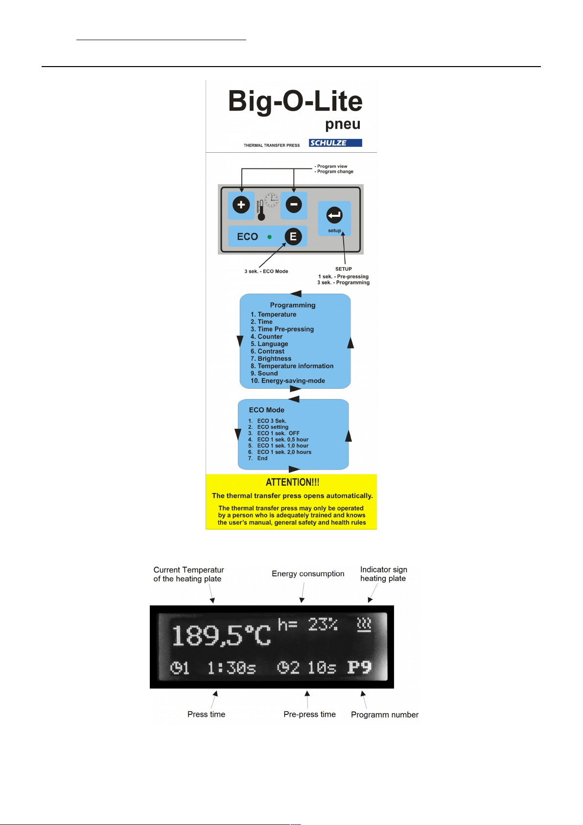
Schulze Big-O-Lite pneu plus User manual

Instruction manual
Version 16.01
Heat press
Big-O-Lite
pneu plus
Version 16.01 1 / 18

1. Introduction
1.1 Content
1. Introduction 02
1.1 Content 02
1.2 Illustration of the heat press 03
1.3 Technical data 03
1.4 Exchangea le heating plates 04
1.5 Exchangea le ase plates 04
1.6 Safety arrangements of the press 04
1.7 Safety arrangements at the workspace 05
2. Initiation 05
2.1 Tips for transport 05
2.2 Installation of the heat press 05
2.3 Connection of the press to compressed air 06
2.4 Power supply 06
2.5 Initiation of the heat press 06
3. Working wit t e eat press 07
3.1 Programming of electronic devices 07
3.2 Resetting of the electronic devieces 09
3.3 Error reports 09
3.4 ECO mode 10
3.5 Prepressing 10
3.6 Application range and sample adjustments of the heat press 10
3.7 Pressure settings 10
3.8 Exchanging the heating plate 11
3.9 Exchanging the ase plate 11
4. Maintenance 12
4.1 Daily Maintenance 12
4.2 Monthly Maintenance 12
4.3 Activation the main fuse 12
4.4 Replacing the power supply 13
4.5 Replacing the electronic devices 13
4.6 Replacing the electronics key oard 13
4.7 Replacing the silicon mat 14
4.8 Replacing the thermal fuse 14
4.9 Trou leshooting 15
4.10 Connection diagram 16
4.11 Controlling of the pneumatics 17
4.12 Testing report 18
4.13 EC-Conformance-Declaration 18
Version 16.01 2 / 18

1.2 Illustration of t e eat press
1. The press ta le
2. Base
3. Base plate with silicon ru er
4. Extracta le handles for the heating plate
5. Heating plate
6. Emergency push utton
7. The electronics key oard
8. Display of the electronic devices
9. Pressure reading
10. Press key START
11. Connector of the heating plate
12. Spiral tu e
13. The drawer
14. Handle to pull out the ase plate
15. Contact pressure adjustment
16. Compressed air connection
17. Air filter with water separator
18. Extracta le handles
19. Main switch
1.3 Tec nical data
Dimensions of the press …................................................. 95 x 80 x 75 cm
Weight …............................................................................................. 95 kg
Operating voltage ….............................................…………............ 230VAC
Main fuse ….......................................................................................... 16A
Max. Temperature …......................................................................... 220°C
Temperature range…................................................................... 0 – 220°C
Time settings …....................................................... 1 sek. - 99 min. 59 sek.
Working plates …................................... 40 x 50 cm, 50 x 80 cm, 70 x 90 cm, 60 x 100 cm, 70 x 100 cm
Heating plates ….................................... 40 x 50 cm, 50 x 80 cm, 70 x 90 cm, 60 x 100 cm, 70 x 100 cm
Version 16.01 3 / 18

1.4 Exc angeable eating plates
For the press there are several heating plates availa le.
The instruction for the exchange you can find in chapter 3.7.
1. Heating plate 40 x 50 cm
2. Heating plate 50 x 80 cm
3. Heating plate 70 x 90 cm
4. Heating plate 60 x 100 cm
5. Heating plate 70 x 100 cm
1.5 Exc angeable base plates
For the press there are several aseplates availa le.
The instruction for the exchange you can find in chapter 3.8.
1. Working plate 40 x 50 cm
2. Working plate 50 x 80 cm
3. Working plate 70 x 90 cm
4. Working plate 60 x 100 cm
5. Working plate 70 x 100 cm
1.6 Safety arrangements of t e press
The Big-O-Lite pneu is equipped with different safety arrangements, to make a safe usage possi le.
Main fuse 16A
The main fuse 16A is located in the lower of the heat press. In case of an overcharge, the main fuse prevents the heat press from getting
damaged. Once the fuse was activated, it has to e replaced. The instruction for replacing the main fuse can e found in chapter 4.3
T ermal fuse
The thermal fuse is placed directly on the heating plate and it stops the power supply if the temperature exceeds 260°C. If this fuse is
activated, the temperature sinks down to 90°C. After that the power supply gets activated again and the temperature of the heating plate
rises and you can work with the press again. Certainly you need to install a new thermal fuse within the next days. The instruction for the
replacement of the thermal fuse can e found in chapter 4.9.
Automatic switc -off
If the press doesn't get opened within 15 seconds after the pressing progress, the heating element switches off automatically, to avoid fire
danger.
Safety valve
The safety valve 6.0 ar is placed at the pressure pipe in the press. I the pressure should exceed 6.0 ar, the valve will e activated
automatically.
Emergency s ut-off
In dangerous situations you may just push the red utton at the front of the press. The press will open automatically. To resume your work
pull the utton to you.
Version 16.01 4 / 18

1.7 Safety arrangements at t e workspace
Set-up and installation of t e eat press
The set-up and installation of the press has to e done under supervision of an authorized person. The installation has to e done y 2 or
more persons following the instructions of this manual.
Testing t e eat press
After a correct installation of the press it is important to ensure that the press works properly, isn't damaged and has no safety defects. The
testing can only e done y the employer or other authorized persons and is mandatory to guarantee correct installation and safe usage of
the press. The testing should e protocoled.
If any irregularities regarding functionality or safety are found during the testing, these have to een noted and reported to Walter Schulze
Gm H in written form within 7 days. Until clarification the press can not e used.
Information and Education
According to § 81 industrial relations law and § 14 employment protection law the employer has to make arrangements to give all
information a out the function and the range of application to the user.
In particular the user needs to e acquainted with the complete manual and e explicitly informed of the dangers of working with the press.
The details have to e explained in a coherent form and language.
Safety distance and ventilation
The press has to e installed at a place which gives enough space on oth sides to put the material on.
The space in front of the press has to e wide enough to let nothing distur the user at work.
Using the press with certain materials may create a strong smell. That’s why the user should evaluate the need for a ventilation system at
the workplace.
Safety instruction:
• The press should only e used y trained personal after notice of this manual
• Only one person is allowed to work on the press at a time.
• Beware of heating plate – risk of urns.
• Attention, the press opens automatically – keep the safety clearance
• The plug has to e pulled out of the power outlet while maintenance.
• Caution: please do not connect this press to any other outlet (socket) than those equipped with ground-fault protection ELCB (earth
leakage circuit reaker).
2. Initiation
2.1 Tips for transport
The SCHULZE Big-O-Lite is covered in protective foil for transport and fixed onto the pallet. Right after the receiving you should check if
the foil and the press are in good condition. Later on, if you have to send the press somewhere, we ask you to fix the press in the same
way on the pallet. The press has to e cold for the transport.
2.2 Installation of t e eat press
Remove the protective foil. The press is placed on a metal plate with handles for easier transport. The press should e transported y 2
people. The device must e carried carefully with attention to proper alance. The press may e located on a special, metal closet, which
must e assem led as instructed.
Instruction for t e closet assembly:
1. Using a hex key screw the closet walls and vertical connectors together (p otos 1-2)
2. Insert protective caps (p otos 3-5)
3. Place the metal shelf in the closet (p otos 6-7)
Version 16.01 5 / 18

Place the press on the closet and connect it using screws. It will prevent the press from sliding. (p otos 8-9)
2.3 Connection of t e press to compressed air
The Airpress is a pneumatic press, which has to e connected to compressed air. The maximum pressure inside the press must not
exceed 6 ar. The air has to e dry and clear of oil. If required you may employ additional filter and drier. The port for the compressed air
at the press is equipped with a quick connect.
After working with the press disconnect the compressed air. So the container with the condensed water will empty automatically. If you
compressed air system isn't equipped with an air drier, you need to check the container every 4 hour and empty it. Therefore press the
kno A (p oto 1) upwards.
To remove the container, disconnect the compressed air first. Push the container up and turn it to the left, now you may remove it. If there
is oil in the container you need to switch off the press at once and repair the compressor. Oil in the system may e damage the press.
2.4 Power supply
The Big-O-Lite has to e connected to a voltage of 230VAC/ 50Hz. The press is equipped with a plug. Make sure that the power outlet is
in the right condition and that the grounding is connected to the power outlet.
Caution: please do not connect this press to any other outlet (socket) than those equipped with ground-fault protection ELCB (earth
leakage circuit reaker).
2.5 Initiation of t e eat press
The press should only e used y trained personal after notice of this manual. Before the initial start up make sure that the power outlet
is in the right condition and that the grounding is connected to the power outlet.
While powering up the press, the mova le part has to e in the upper position, which means that the press has to e open. The press
also has to e open while heating up.
The press can e turned on with the ig dip-switch (p oto 1). The press heats up to the adjusted temperature.
Start the press with oth green uttons START (p oto 2). Connect the press to the compressed air, the pressure must not exceed 6 ar.
If your are not using the press, please disconnect the compressed air.
After finishing the work with the press the switch has to e turned off and the plug has to e pulled out.
If you want to e off the press efore the end of press time, press the emergency stop switch (p oto 3).
Version 16.01 6 / 18

3. Working wit t e eat press
3.1 Programming of electronic devices
Version 16.01 7 / 18

Pre-pressing
To activate the pressing process, press utton 1 (confirmation). On the display there's the pre-
pressing time 2. After the pre-pressing the adjusted time for the normal pressing appears on
the display.
Programming of t e electronic devices
1. Press utton 1 for 5 seconds.
The display shows: Temperature.
2. With the uttons + and – you can adjust the temperature.
3. Press utton 1.
The display shows: Time 1.
4. With the uttons + and – you can adjust the pressing time.
5. Press utton 1.
The display shows: Time Pre-pressing 2.
6. With the uttons + and – you can adjust the pre-pressing time.
7. Press utton 1.
The display shows: Counter.
8. With the uttons + and – you can switch the counter on/off.
9. After switching on the counter it counts the num er of pressing activities.
a. To end the programming of the electronic devices press utton 1.
. to get to the advanced programming menu, press utton 1 for 3 seconds.
The display shows: Language.
1. With the uttons + and – you can change the language (German, Polish,
English, Russian and French).
2. Press utton 1.
The display shows: Contrast.
3. With the uttons + and – you can adjust the contrast of the display.
4. Press utton 1.
The display shows: Brig tness.
5. With the uttons + and – you can adjust the rightness of the display.
6. Press utton 1.
The display shows: Settings of temperature information
7. With the uttons + and – you can choose if the actual or the adjusted temperature should
e shown on the display.
8. Press utton 1.
The display shows: Sound.
9. With the uttons + and – you can switch the sound of the press on/off.
10. Press utton 1.
Version 16.01 8 / 18

The display shows: Energy-saving-mode.
11. With the uttons + and – you can switch the energy-saving-mode on/off.
12. Press utton 1.
The display shows: Overall counter.
Here you can see the num er of all pressing activations.
13. Press utton 1.
The display shows: Hours of work.
Here you can see the num er of hours the press has worked.
14. press utton 1.
The display shows: Diagnostic function.
Here you can check the electric circuits: - temperature fuse
- thermo couple
- power relay
15. To end the programming mode, press utton 1.
3.2 Resetting of t e electronic devices
Attention!
You only s ould reset t e eat press after getting in contact wit t e producer.
To reset the heat press, press utton 1 and 2 at the same time. Button 1 should e pressed 1
second earlier. Hold the uttons 20 sec.
Confirm the action with utton 2 or cancel it with utton 3. If you press the utton YES the
Temperature will change to the original setting.
3.3 Error reports
The electronic devices of the Big-O-Lite pneu control the main functions of the press.
Here is a list of possi le messages:
ERR.1 – No connection of the electronic devices to the temperature sensor. (Temperature sensor defect/ ca le not connected)
ERR.2 – Connection of electronic devices and temperature sensor ypassed. (Temperature sensor defect/)
ERR.3 – Resistor of temperature sensor too low. The temperature range of the electronic devices is deceeded.
ERR.4 – Resistor of temperature sensor too high. The temperature range of the electronic devices exceeded.
ERR.5 – No temperature rise within 3 minutes even if heating element is switched on. (Temperature fuse is defect)
ERR.6 – No reduction of the temperature within 3 minutes even if heating element is turned off. (Power relay CRYDOM is defect)
ERR.7 – Temperature too high, over 230°C (Power relay CRYDOM is defect)
ERR.3 and ERR.4 can occur if the electronic devices are not programmed properly.
Version 16.01 9 / 18

3.4 „ECO“ mode
With the ECO mode you will save power. If the ECO mode 1, 2 or 3 is active, the electronic devices will control the progress of work of
the press. If you should have forgotten to turn-off the press, never mind, the ECO mode will deactivate it. In phase 1 of the ECO mode,
while the press is momentarily not in use, the temperature will decrease 50°C (a 3 second long acoustic signal will sound). In phase 2, if
the press is furthermore not in use, the heating elements will e deactivated to save power (5 sec. acoustic signal).
3.5 Prepressing
Prepressing will activated with Button Setup. With an adjusted prepress time, e.g. 2 s, the press will close for 2 seconds. After that the
adjusted pressing time will automatically e activated.
3.6 Application range and sample adjustments of t e eat press
This press is used to put transfers and transfer films on textiles. To get good achievements, get in contact with the producer of the textiles.
Here are some settings:
Film Flex 150°C – 160°C Time 15 Seconds
Film Flex S 155°C – 160°C Time 15 Seconds
Film A-Flex 155°C – 160°C Time 15 Seconds
Film Flock 160°C – 180°C Time 15 Seconds
Su limation Film 190°C – 205°C Time 50 Seconds
All information is supplied without lia ility, please run your own testing efore production.
3.7 Pressure settings
With this press you can change the pressure setting.
After every change of the pressure settings, close the heat press to check the new settings.
Damages, w ic arise from to muc pressure, are excluded from t e guarantee.
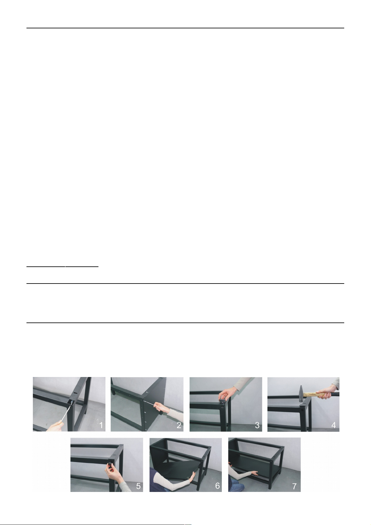
To adjust the pressure do the following:
1. Take the pressure reading. (p oto 1).
2. To alter the pressure pull the kno to you. (p oto 2).
•Rotating the kno to the right will increase the pressure (p oto 2).
•Rotating the kno to the left will decrease the pressure (p oto 2).
3. To retain the setting push the kno to the press again.
4. Test t e pressure (p oto 3).
The pressure reading you may take at the top on the right.
1,0 ar - ca. 415 kg
2,0 ar - ca. 830 kg
3.0 ar - ca. 1245 kg
4.0 ar - ca. 1660 kg
5,0 ar - ca. 2075 kg
6.0 ar - ca. 2490 kg
It is recommended to keep the pressure accordingly
Plate 8 x 16 cm ~ 0,3 ar (max. 0,6 ar)
Plate 20 x 20 cm ~ 0,3 ar (max. 0,6 ar)
Plate 38 x 45 cm ~ 2 ar (max. 4,0 ar)
Plate 40 x 50 cm ~ 2,5 ar (max. 4,5 ar)
If you alter the pressure to a setting higher than 6 ar, a safety valve will e activated. In this case you have to reduce the pressure.
Version 16.01 10 / 18
temperature decreases turn off the heating
elements later
ECO OFF - -
ECO 0,5 30 Minute 60 Minute
ECO 1,0 60 Minute 60 Minute
ECO 2,0 120Minute 60 Minute
a out -50°C

3.8 Exc anging t e eating plate
To exchange the heating plate, the press must be disconnected from electricity and cold.
Now disconnect the spiral tu e plug of the heating plate. (p otos 1-2).
Loosen fixation screw with a wrench (p oto 3). The heating plate must e placed exactly on the lower plate. Large heating plates have
handles for transport. They should e installed (p otos 4-6) and the heating plate must e carefully put on soft surface so as not to
damage the teflon. Then take the new heating plate and tighten it with the wrench. Connect the heating plate with the press.
The heating plate can not e turned.
3.9 Exc anging t e base plate
To replace the lower plate the drawer with the plate must e pulled out (p oto 1), If you want to exchange the ase plate you have to
loosen the fixation screw (p oto 2).
After exchanging the ase plate, you have to tighten the fixation screws again (the pointed sides have to face up).
Version 16.01 11 / 18

4. Maintenance
4.1 Daily Maintenance
The working surface of the heating plate and the ase plate have to e clean. The heating plate can e cleaned with a clean, dry cloth.
Avoid contact with the heating plate – risk of urns.
The silicon gum can e cleaned with a soft cloth. You can use mild household detergent. Avoid scru sponges, solvents or fuel.
Should the press e used continuously over several days, you have to repeatedly in one day pus t e black button right under the air
connection to release the water, which accumulated there (p oto 1).
If t ere is oil in t e container you need to switc off t e press at once and repair t e compressor. Oil in t e system may be
damage t e press.
4.2 Mont ly Maintenance
Before eginning maintenance work, control if t e press is turned off and cold. Disconnect t e press from electricity.
Some mova le parts need to e greased. Greasing is needed 2-3 times a year. You can take normal car grease.
There are 2 points on the heat press, which have to e greased.
1. Under the drawer, oth ta le tracks (p oto 1).
2. Under the ase plate, the four olts (p oto 2).
4.3 Activation t e main fuse
If the heat press does not work after switching on, check the main fuse of the press.
The main fuse 16A is located in the lower of the press. (p oto 2). To activate the fuse, switc off t e eat press first and pull t e plug.
Remove the cover (p oto 1). Turn the fuse y pushing the lever (p oto 3). Then reassem le the press again. (p oto 1).
Version 16.01 12 / 18

4.4 Replacing t e power supply
To exchange the power supply, turn t e press off and disconnect it from power first. Unscrew the cover of the press, as in chapter
4.4. Remove the stopper of the power supply (p oto 1) and pull out the green plug (p oto 2). Replace the power supply (p oto 3).
Connect the green plug and fasten the power supply in the upper part of the press again. Then reassem le the press.
4.5 Replacing t e electronic devices
Inside the upper part of the press there are electronic devices, which control the temperature and time of the press.
To exchange the electronic devices, turn off t e press and pull t e plug.
Unscrew the cover of the press, as in chapter 4.4. Pull out the green plug (p oto 1). Pull out the electronics key oard (p oto 2). Remove the
stopper of the electronic devices (p oto 3). Remove the electronic devices ((p oto 4). Connect the new electronic devices and fix them into the
press . Then reassem le the press again.
4.6 Replacing t e electronics keyboard
To change the electronics key oard t e press must be switc ed off and unplugged.
Remove the front covers, as in chapter 4.4.
Disconnect the plug of the electronics key oard from the electronics (p oto 1).
Remove the key oard from the press (p oto 2). Install a new key oard and connect the plug to the electronics. Reassemble t e press.
Version 16.01 13 / 18

4.7 Replacing t e silicon mat
To exchange the silicon mat the press must e disconnected from the electricity and cold. For the exchange you need a new silicon mat,
silicon glue, acetone and a notched trowel.
1. Remove the silicon mat with a knife restless.
2. Put an equal film of silicon glue on the plate using the notched trowel.
3. Put on the new silicon mat.
4. Close the pressure lever to press the silicon mat and the plate together.
5. Open the pressure lever and make sure that the plate and the mat lays exactly over each other.
6. Let the glue dry for 24hours.
7. Take of the heating plate and cut off the overlaying edge of the silicon mat.
4.8 Replacing t e t ermal fuse
The replacing may only e done y an authorized person.
For the replacement of the thermal fuse, the heat press must be disconnected from t e electricity and cold. Remove the cap from the
heating plate and remove the heat isolation (p oto 1). Then remove the thermal fuse (p oto 2) and connect a new one (p oto 3).
Tighten it on the heating plate, put in the heat isolation and tighten the cap again. If you have the heating plate 400 x 500 mm the same
should e done with the second thermal fuse (p oto 4).
Version 16.01 14 / 18

4.9 Troubles ooting
Version 16.01 15 / 18
Pro lem Cause De ugging
Main fuse 12 A is defect Replace main fuse 12 a
The main switchs glows, ut If the main fuse is okey, check if the diode in the power supply Replace fuse 1,6A in the power supply
the display isn't is glowing. If not the fuse or the power supply is defect or replace the power supply
the heating plate isn't heating up If the diode is glowing
Replace the electronic devices
the electronic devices are defect
The display shows ”Err.5” Thermal fuse on the heating plate is defect
Replace the thermal fuse
If you use the heating plate 400x500mm replace
oth thermal fuses
The display shows ”Err.1”
Thermo couple is defect or the ca les to the Check the ca les to the thermo couple
thermo couple are defect or exchange the thermo couple
No connection to the heating plate Put the plug of the heating plat into the socket
The display shows ”Err.2” The thermo couple is defect Exchange the thermo couple
The display shows ”Err.3” Resistance of the thermo couple is too low Exchange the thermo couple
The display shows ”Err.4” Resistance of the thermo couple is too high
The display shows ”Err.6” Power relay CRYDOM is defect Replace power relay CRYDOM
The display shows ”Err.7”
Adjustment uttons aren't working Adjustment uttuns are defect Replace adjusment uttons
No time or temperature adjustments are possi le
Temperature of the heating plate doesn't correspond to the Malfunction of the electronic devices Reset the electronic devices, ut
Temperature on the display – Temperature too high/low first contact Walter Schulze Gm H
The press heats up very slowly – over 30 minutes One of the tow heating elements is defect Replace the heating plate and/or send it in for repairs
one half of the plate doesn't reach the adjusted temperature
The press will not stay down Micro switch is defect Mikroschalter einstellen oder Mikroschalter austauschen
The time is not activated The Material is to thick and so the micro switch isn't activated
The press will not close Emergency utton is pressed down Pull the emergency utton out
Compressed air is not connected Connect the compressed air
The press will not open Pneumatic valve is defect Replace the pneumatic valve

4.10 Connection diagram
Version 16.01 16 / 18

4.11 Controlling of t e pneumatics
Version 16.01 17 / 18

4.12 Testing report
final check of the heat press:
o - ase, paint
o - greasing of the waves
o - heating plate and ase plate, silicon, Teflon
o - electronic connection, safety wire, power ca le
o - electronic, max. temperature 220°C
o - check of all functions
o - working time at 180°C . . . . . . . hours
o - temperature tolerance at 180°C . . . . . . -/ . . . . . .+°C
o - working time at 220°C . . . . . . . .hours
o - test with a transfer film
o - caution la els
Serial num er . . . . . . . . . . . . . . . . . . Date . . . . . . . . . . . . . . . . . . . . Signature . . . . . . . . . . . . . . . . . . . . . . . . . . .
4.13 EC-Conformance-Declaration
The Walter Schulze Gm H
Ha erstraße 15 - 19
12057 Berlin
as European representative of the manufacturer company ROMANIK here y declares that the following machine:
Heat press ………………….. serial num er…...………………...
is compliant with the specifications of the following EC directives:
Machinery (2006/42/EC)
Low Voltage (2014/35/EU)
EMC (2014/30/EU)
used norms and technical specifications:
PN-EN ISO 12100:2012
PN-EN 60204-1:2010
PN-EN 61000-6-1:2008
PN-EN 61000-6-3:2008/A1:2012
PN-EN 60335-1:2012
Applied quality system: testing report / 2016
Noise: The machine generates noise less than 70 dB A
Berlin , . . . . . . .
_____________________________
Peter Meidinger
President
All SCHULZE machines are exempt from the waste disposal law under reg. no. DE 231060054.
Manufacturer ROMANIK, ul. Przemysłowa 10, 84-240 Reda, www.romanik.pl
Distri utor: Walter Schulze Gm H Ha erstraße 15-19, 12057 Berlin, www.schulzeshop.com
Version 16.01 18 / 18
Table of contents
Other Schulze Industrial Equipment manuals

Schulze
Schulze BluePRESSLine CAP User manual

Schulze
Schulze PRETREATmaker 5 User manual

Schulze
Schulze Mug 1 Press User manual

Schulze
Schulze PRETREATMaker III User manual

Schulze
Schulze DTF PowDR User manual

Schulze
Schulze PRETREATmaker LINE 7-4 User manual

Schulze
Schulze PRETREATmaker IV User manual

Schulze
Schulze BLUEpress User manual