Schulze BluePRESSLine CAP User manual

Instruction manual
Version 11.01
heat press
BluePRESSLine
CAP
Version 11.01 1 / 13

1. Introduction
1.1 Content
1. Introduction 02
1.1 Content 02
1.2 Illustration of the heat press 03
1.3 Technical data 03
1.4 Safety arrange ents of the heat press 04
1.5 Safety arrange ents at the workspace 04
2. Initiation 05
2.1 Tips for transport 05
2.2 Installation of the heat press 05
2.3 Power supply 05
2.4 Initiation of the heat press 05
3. Working wit t e eat press 06
3.1 Progra ing electronic devices 06
3.2 Application range and sa ple adjust ents of the heat press 07
3.3 Pressure settings 07
3.4 Turnbuckle for Cap's 07
4. Maintenance 08
4.1 Daily Maintenance 08
4.2 Monthly Maintenance 08
4.3 Replacing the ain fuse 09
4.4 Replacing electronic devices 09
4.5 Replacing the silicon at 09
4.6 Replacing the ther al fuse 10
4.7 Replacing the te perature sensor 10
4.8 Troubleshooting 11
4.9 Connection diagra 12
4.10 Testing report 13
4.11 EC-Confor ance declaration 13
Version 11.01 2 / 13

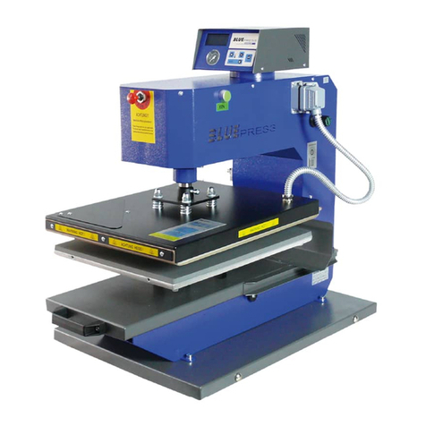
1.2 Illustration of t e eat press
1. electronic devices
2. base plate
3. heating plate
4. pressure lever with power grip
5. cable with connector
6. turnbuckle lever
7. contact pressure adjust ent
8. turnbuckle
9. ain switch
10. ain fuse
11. gas pressure spring 150 N
12. spiral tube
1.3 Tec nical Data
Di ensions of the press: …............................. 42 x 18 x 40 c
Working plate: ….......................................................... 8 x 16 c
Weight: ................................................................................15 kg
Operating voltage: ......................................................... 230VAC
Fuse: .................................................................................…. 6A
Max. pressure: ................................................................. 300 kg
Te perature range: .................................................... 0 - 220 °C
Ti e settings: …................................................. 1sek – 9:59 in
Version 11.01 3 / 13

1.4 Safety arrangements of t e eat press
The bluePRESSLine CAP is equipped with different safety arrange ents, to ake a safe usage possible.
Main fuse 6A
The ain fuse 6A is placed at the right side of the heat press, next to the ain switch. In case of overcharge the ain fuse prevents the
heat press fro getting da aged. Once the fuse was activated it ust be replaced. The instruction for the exchange you can see in
chapter 4.3.
T ermal fuse
The ther al fuse is placed in the left corner on the heating plate and stops the power supply, if the te perature is exceeded too uch.
Acoustic signal
3 Seconds before the end of the pressing process an acoustic signal will sound.
1.5 Safety arrangements at t e workspace
Testing t e eat press
After a correct installation of the press it is i portant to ensure that the press works properly, isn't da aged and has no safety defects. The
testing can only be done by the e ployer or other authorized persons and is andatory to guarantee correct installation and safe usage of
the press.
If any irregularities regarding functionality or safety are found during the testing, these have to been noted and reported to Walter Schulze
G bH in written for within 7 days. Until clarification the press can not be used.
Information and Education
According to § 81 industrial relations law and § 14 e ploy ent protection law the e ployer has to ake arrange ents to give all
infor ation about the function and the range of application to the user.
In particular the user needs to be acquainted with the co plete anual and be explicitly infor ed of the dangers of working with the press.
The details have to be explained in a coherent for and language.
Safety distance and ventilation
The press has to be installed at a place which gives enough space on both sides to put the aterial on.
The space in front of the press has to be wide enough to let nothing disturb the user at work.
Using the press with certain aterials ay create a strong s ell. That’s why the user should evaluate the need for a ventilation syste at
the workplace.
Safety instruction:
•The press should only be used by trained personal after notice of this anual
•Only one person is allowed to work on the press at a ti e.
•Beware of heating plate – risk of burns.
•The plug has to be pulled out of the power outlet while aintenance.
•Caution: please do not connect this press to any other outlet (socket) than those equipped with ground-fault protection ELCB
(earth leakage circuit breaker).
Version 11.01 4 / 13

2. Initiation
2.1 Tips for transport
The BluePRESSLine CAP is covered with a cardboard for transport. Right after the receiving you should check if the cardboard and the
press are in good condition. Later on, if you have to send the press so ewhere, we ask you to cover the press with the sa e cardboard
and in the sa e way. The press has to be cold and the pressure lever has to be pulled down.
2.2 Installation of t e eat press
The heat press is delivered in a cardboard. After unpacking and connecting heat press can be worked with. The BluePRESSLine CAP
heat press do not need any other installations.
2.3 Power supply
The BluePRESSLine CAP has to be connected to a voltage of 230VAC/ 50Hz. The press is equipped with a plug. Make sure that the
power outlet is in the right condition and that the grounding is connected to the power outlet.
Caution: please do not connect this press to any other outlet (socket) than those equipped with ground-fault protection ELCB (earth
leakage circuit breaker).
2.4 Initiation of t e eat press
While powering up the press, the ovable part has to be in the upper position, which eans that the press has to be open. The press also
has to be open while heating up. The press can be turned on with the green switch. If the green switch glows the press heats up to the
adjusted te perature. After finishing the work with the press the switch has to be turned off and the plug has to be pulled out.
Version 11.01 5 / 13

3. Working wit t e eat press
3.1 Programming of electronic device
After switching on the press, the current te perature is
shown on the display and the press heats up.
C ange settings:
1. The progra ing ode shows up when you press
Button 1 for about 5 seconds, until the LED blinks up.
2. LED1 blinks and the progra ed te perature shows up
on the display. The progra ing ode is activated.
3. T e temperature gets progra ed with button 2 and 3.
4. Press Button 1 s ortly.
On the display you can see the progra ed ti e.
You can progra the ti e by pressing Button 2 and 3.
5. Press Button 1 s ortly to save the changes and leave
the progra ing ode.
or:
6. To get to the ECO progra ing, press Button 1 for 3
seconds.
7. With Button 2 and 3 you can switch between the
ECO odes:
„Eco 0” - ECO ode turned off,
„Eco 1” - ECO ode turned on
8. To leave the progra ing ode press Button 1.
TEMPERATURE TIME
Control of t e preset temperature
If you want to control which te perature is adjusted at the
o ent, press button 2(+). The te perature shows up on the
display.
Control of t e preset time
If you want to control which ti e is adjusted at the o ent,
press button 3(-). The ti e shows up on the display.
"ECO" Mode
The "Eco" Mode is a special econo ic ode, which cools down the o entarily unused press about 50°C and turns off the heating
ele ents later. Both will be signaled acustically.
1. After not using the press for 30 inutes, the te perature decreases about 50°C.
2. After not using the press 90 inutes, the heating ele ents turn off.
T e press gets activated again by pus ing any button at t e press.
Version 11.01 6 / 13
3.2 Application range and sample adjustments of t e eat press
This press is used to put transfers and transfer fil s on textiles. To get good achieve ents, get in contact with the producer of the textiles.
Here are so e settings:
Fil Flex 150°C – 160°C Ti e 15 Seconds
Fil Flex S 155°C – 160°C Ti e 15 Seconds
Fil Flock 160°C – 180°C Ti e 15 Seconds
Fil Velcut 150°C – 160°C Ti e 15 Seconds
All indications without warranty, please do your own testing before producing.
3.3 Pressure adjustments
The pressure gets adjusted at the rotary knob on the upper lever. The pressure can only be changed when the heat press is opened. If the
pressure is too high the heating plate could be da aged. Because you can't read the pressure on a display, you have to do tests to ake
sure the pressure is right.
You can adjust the pressure very exactly. To do this, follow
this explanation:
1. Put a textile on the workplate.
2. Close the heat press and control the pressure, after that,
open the heat press.
•Turn the knop right to increase the pressure.
•Turn the knop left to decrease the pressure.
3.4 Turnbuckle for Cap's
To chuck the caps into the heat press pull the lever down (p oto 1). The turnbuckle ust be placed directly under the base plate
(p oto 2). Now put the cap on the base plate (p oto 3) and pull up the turnbuckle lever (p oto 4).
Version 11.01 7 / 13

4. Maintenance
4.1 Daily Maintenance
The working surface of the heating plate and the base plate have to be clean. The heating plate can be cleaned with a clean, dry cloth.
Avoid contact with the heating plate – risk of burns. The silicon gu can be cleaned with a soft cloth. You can use ild household
detergent. Avoid scrub sponges, solvents or fuel.
4.2 Mont ly Maintenance
Before beginning aintenance work control if t e press is turned off and cold. Disconnect t e press from electricity. So e ovable
parts need to be greased. Greasing is needed after every 200 ours of usage. You can take nor al car grease which is eat resistant
up to 160°C.
There are 4 points on the heat press, which have to be greased after 200 hours of usage.
While greasing you have to ove the pressure lever up and down slowly.
1. Down, on the connection part (p oto 1).
2. On the pressure lever (p oto 2).
3. On the pressure lever (p oto 3).
4. Up, on the connection part (p oto 4).
Version 11.01 8 / 13

4.3 Replacing t e main fuse
If the heat press does not work after switching on, check the ain fuse of the press.
The ain fuse 10 A is placed at the right side of the heat press (p oto 1). To exchange the fuse, switc off t e eat press first and
pull t e plug. There are additional fuses in the anual. Then re ove the fuse bracket (p oto 1). Pull out the ain fuse (p oto 2).
Replace the fuse (p oto 3) and tighten the fuse bracket again (p oto 4).
4.4 Replacing t e electronic devices
Inside the heat press are the electronic devices, which are controlling the ti e and the te perature. For an exchange of the electric
devices turn off t e press and pull t e plug. Release the fixation screws (p oto 1). Take out the electronic devices (p oto 2).
Disconnect the green plug (p oto 3), put it in the new electronic devices and reasse ble the press again.
4.5 Replacing t e silicon mat
To replace the silicon at t e press as to be cold and disconnected from t e electricity. For the exchange you need a new silicon
at, silicon glue, acetone and a notched trowel.
1. Re ove the silicon at co pletely with a knife .
2. Clean the plate and the new silicon at with acetone.
3. Put an equal fil of silicon glue on the plate using the notched trowel.
4. Put on the new silicon at.
5. Close the pressure lever gently to press the silicon at and the plate together.
6. Make sure that the plate and the at lays exactly over each other.
7. Re ove re aining glue or overlapping at fro the edges of the press.
8. Let the glue dry for 24hours. Only then open the press.
Version 11.01 9 / 13

4.6 Replacing t e t ermal fuse
For the exchanging of the ther al fuse, t e press must be disconnected from t e electricity and cold. Release the screw on top of the
heating plate (p oto 1), place it on the base plate (p oto 2) and unscrew the four screws in the heating plate (p oto 3). Thereby ind the
springs. Re ove the Cover of the heating plate (p oto 4). Take out the ther al insulation, unscrew the ther al fuse (p oto 5) and
connect a new one. Screw it to the heating plate, set in the ther al insulation and reasse ble the press again.
4.7 Replacing t e temperature sensor
For the exchanging of the te perature sensor t e eat press must be disconnected from t e electricity and cold. Re ove the Cover
of the heating plate as described in replacing the ther al fuse, chapter 4.6. Than re ove the 2,5 allen screw with an allen screwdriver
(p oto 1). Take out the te perature sensor (p oto 2) and put in a new one. After that you screw it in tightly put in the heating insulation
and fix the heating plate on the heat press.
Version 11.01 10 / 13

4.8 Troubles ooting
Version 11.01 11 / 13
Proble Cause Debugging
Green switch blink, but: ain fuse 6 A is defect Exchange ain fuse 6 A
display doesn´t glow If ain fuse is okay, than check Exchange electronic devices
plate doesn´t heat
heatpress doesn´t heat up to adjusted te perature ther al fuse on heatplate is defect Exchange ther al fuse
even if the red diode glows
after switching on, te perature rises
but falls after short ti e
the display just shows 4 dashes te perature sensor defect or cable broken check cable to t eperature sensor
no te perature or ti e infor ation or exchange te perature sensor
no acustic signal after end of pressing beeper is defect Exchange electronic devices
te perature rises ore, than it should
even the red diode doesn´t glow
te peratue rises to 180°C – the red diode glows up solid state relay CRYDOM is defect exchange solid state relays CRYDOM
After reaching - the diode doesn´t glow
Te perature rises ore than 220°C, than it is sinking
to circa 90°C and rises again to 220°C
Button doesn´t work setting buttons are defect exchange setting buttons
no settings possible in te perature and ti e
reset electronic devices
real te perature doesn´t atch with te perature breakdown of electronic devices exchange setting buttons
Shown on the display – te perature too high/low
Examplel:temperature 180°C was regulated

4.9 Connection diagram
Version 11.01 12 / 13

4.10 Testing report
final check of the heat press:
o- base, paint
o- greasing of the waves
o- heating plate and baseplate, silicon, teflon
o- electronic connection, safety wire, power cable
o- electronic, ax. te perature 220°C
o- check of all functions
o- working ti e at 180°C . . . . . . . hours
o- te perature tolernace at 180°C . . . . . . -/ . . . . . .+°C
o- working ti e at 220°C . . . . . . . .hours
o- test with a transfer fil
o- caution labels
Serial nu ber . . . . . . . . . . . . . . . . . . Date . . . . . . . . . . . . . . . . . . . . Signature . . . . . . . . . . . . . . . . . . . . . . . . . . .
4.11 EC-Conformance-Declaration after EC- guideline for mac ines 2006/46 EC
The Walter Schulze G bH
Sch alenbachstraße 15
12057 Berlin
as European representative of the anufacturer co pany ROMANIK hereby declares that the following achine:
Heat press . . . . . . . . . . . . . . . Serial nu ber . . . . . . . . . . . .
is co pliant with the specifications of the following EC directives:
Machinery ( 2006/46)
Low Voltage (2006/95)
EMC (2004/108)
used nor s and technical specifications:
EN 292-1 EN 292-2 safety of achines
EN 60204-1 electrical equip ent of achines
Berlin , . . . . . . .
_____________________________
Peter Meidinger
President
All SCHULZE heat presses are exce pt fro the waste disposal law under reg.no. DE 231060054.
Version 11.01 13 / 13
Table of contents
Other Schulze Industrial Equipment manuals

Schulze
Schulze PRETREATmaker IV User manual

Schulze
Schulze PRETREATMaker III User manual

Schulze
Schulze PRETREATmaker 5 User manual

Schulze
Schulze Mug 1 Press User manual

Schulze
Schulze Big-O-Lite pneu plus User manual

Schulze
Schulze PRETREATmaker LINE 7-4 User manual

Schulze
Schulze DTF PowDR User manual

Schulze
Schulze BLUEpress User manual