SDC 950 ENTRYCHECK Installation manual

Security Door Controls
3580 Willow Lane, Westlake Village, CA 91361-4921 • (805) 494-0622 • Fax: (805) 494-8861
www.sdcsecurity.com • E-mail: service@sdcsecurity.com
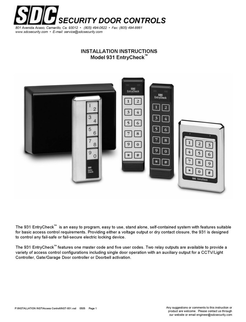
The EntryCheck™incorporates all
the logic necessary to control a
single door. All Unit Programming
is performed by using the built-in
keypad. Proximity cards, key fobs
and PIN entries can be added and
deleted with the keypad using the
master code or programming card.
The lock relay and alarm relay
outputs can be set for 1-99
seconds.
CHOICE OF ENTRY MODE
The SDC EntryCheck™provides a
choice of three programmable entry
modes:
• Proximity Reader Only
• Proximity Reader or PIN Code
• Proximity Reader and PIN Code
WALL OR GLASS MOUNTED
The weather resistant unit is easily
surface mounted to the wall either
inside or outside. An optional glass
mounting kit is available. When the
EntryCheck™is mounted to the
interior side of a glass sidelight or
store front, the proximity reader may
be activated from the exterior
through the glass.
FEATURES
• Up to 500 Cards and/or PIN Codes
• Choice of three entry modes:
Proximity Reader only
Proximity Reader or PIN Code
Proximity Reader and PIN Code
• Up to 6 inch (152 mm) reader range
• Add / change / delete cards and
PINs
• Programmable door unlock
time from 1 - 99 seconds
• Tamper alarm and reader/PIN
lockout
• Request-To-Exit input
• Two outputs, lock relay and
alarm relay
• LED and audible tone for
operation ease.
• Weather resistant
ORDERING INFORMATION
950C Prox / PIN reader w/10 cards
950K Prox / PIN reader w/10 key fobs
C10 Ten SDC prox cards
K10 Ten SDC key fobs
950GL-KIT Interior glass mounting kit
TR12 12VDC Plug-in power supply with
AC ground and two fused outputs.
Access control output: 150 mA filtered /
regulated. Lock output: 780 mA filtered.
USER INFORMATION
To open door using card and PIN
Present Card (LED flashing red)
Enter PIN (LED green)
To open door using PIN only
Enter PIN number (LED green)
To open door using card only
Present card to reader (LED green)
INSTALLATION/PROGRAMMING INSTRUCTIONS
950 ENTRYCHECK™
Any suggestions or comments to this instruction or
product are welcome. Please contact us through
our website or email engineer@sdcsecurity.com
P:\INSTALLATION INST\Access Controls\INST-950\INST-950.vsd REV G 0605 Page 1

PROGRAM MASTER CARD
Apply power (LED flashing yellow).
Enter 000000 (6 beeps).
Enter 2(LED flashing green; 1 beep).
Present Master card to reader and
Remove (LED flashing green; 1 beep).
Enter #(LED flashing yellow; 6 beeps).
PROGRAM UNLOCK TIME (Default is 1 sec)
Enter .
Present Master card to reader and Enter .
Remove (6 beeps).
Enter 4 (LED flashing green).
Enter delay on relock time
(i.e. 03 = 3 sec.). Default is 1 sec.
Enter (1 beep, green LED).
Enter #(6 beeps).
Note: 00 = Toggle
PROGRAMMING ENTRY MODE
Choose the mode of entry you require.
0 = CARD and PIN (Default)
1 = CARD Only
2 = CARD or PIN
-------------------
Enter .
Present Master card to reader and Remove (6 beeps).
Enter 5 (LED flashing green).
Enter 0, 1 or 2.
Enter #(6 beeps).
PROGRAMMING ONE CARD & PIN
Enter (1 beep, green LED).
Present Master card to reader.
Remove (6 beeps).
Enter 1(LED flashing green).
Enter 01 001 (delayed 1 beep). (001-499)
Present new card to reader and remove (1 beep).
Key in any 4 digit PIN for new card (1 beep).
Enter # (6 beeps).
Repeat above for every card to be entered.
CARD BATCH PROGRAMMING
Note: PIN will be the same for all cards
programmed in the batch mode.
Enter (1 beep, green LED).
Present Master card to reader and Enter .
Remove (6 beeps, LED flashing red & green).
Enter 1 (1 beep, LED flashing green).
Enter number of cards to be programmed (01-99).
Enter (1 beep, green LED).
Enter starting user number (001-499).
Enter (1 beep, green LED).
Present first sequential card.
Enter 4 digit PIN number (1 beep; LED flashing red & green).
Enter # to exit (6 beeps; LED flashing yellow).
DELETE CARD
Enter . Present Master card to reader and Enter .
Remove (6 beeps, LED flashing red & green).
Enter 7 (LED flashing green).
Present card to be deleted to reader and remove (1 beep).
Enter # (6 beeps).
OR
Enter .
Present Master card to reader and Enter .
Remove (6 beeps).
Enter 7 (LED flashing green).
Key in last six numbers located on card to be deleted.
Enter (1 beep).
Enter #(6 beeps).
RESET TO FACTORY DEFAULTS &
DELETE MASTER CARD
Disconnect power.
While depressing both the and #keys, apply power. The
LED will flash green and then after a few seconds will turn
red. This resets the master code to the default ‘000000’. To
erase all user cards and settings as well as the master code,
continue depressing the & #keys until the red LED goes
out.
Remove power.
Release the & #keys.
Wait 5 seconds.
Reapply power.
NOTE:
•When programming a new card you must enter first to enter the programming mode and present the Master Card.
• PIN needs to be programmed for each new card even if CARD only entry mode is chosen.
•Yellow LED flashing may also be viewed as an alternating red and green LED.
• The #key exits the programming mode (LED flashing yellow).
• Keep a log of each card issued. See sample log on following page.
P:\INSTALLATION INST\Access Controls\INST-950\INST-950.vsd REV G 0605 Page 2

User
Number Name
Card
Number
PIN
Code
User
Number Name
Card
Number
PIN
Code
P:\INSTALLATION INST\Access Controls\INST-950\INST-950.vsd REV G 0605 Page 3

WIRING DIAGRAM
PCB front view
INSTALLATION SETTINGS
Typical Wiring (single door)
P:\INSTALLATION INST\Access Controls\INST-950\INST-950.vsd REV G 0605 Page 4
WARNING
Do not use a
switching power
supply. The
interference
radiation may
disturb the
reading of
badges.
VReturn or V-
12 +12 VDC
O Relay 1 contact (ST2)
CRelay common
TRelay 2 N/O contact
B Request-to-exit input
MCommon for REX & Alarm Input
EDoor Contact
PIN-OUTS
AT1 Anti-Tamper Switch
ST2 Jumper for Relay 1
RL1 Door Relay
RL2 Alarm Relay
V1 Varistor
PB1 REX Push Button
LEGEND
N/C contact RL1 (magnet)
N/O contact RL1
ST2
1
1
3
3
STRIKE
V1
Power
Supply +V
12VDC
110VAC
PB1
2 1 E M B 3 5 T C O 12 V
RL2 RL1
AT1 ST2 31
1
2
3
TR12
POWER
SUPPLY
12VDC
150mA
REGULATED
OUTPUT
12VDC
780mA MAX
(USE WITH NON-SDC LOCKS)
REQUEST TO EXIT
REX (N/O)
MOV ELECTRIC
LOCK (750mA MAX)
SET JUMPER ST2
FOR LOCK TYPE
FAIL SAFE (N/C)
FAIL SECURE (N/O)
950
12 V C O – - M B
Not Used

Template
950 EntryCheck™
Wiring access
Area
3"
(75.5 mm)
2 7/16"
(61 mm)
1 ½”
(38 mm)
9 1/16"
(15 mm)
⅞"
(23 mm)
P:\INSTALLATION INST\Access Controls\INST-950\INST-950.vsd REV G 0605 Page 5
¾”
(20.5 mm)
1 ⅝"
(43 mm)
4 11/16"
(120 mm)
4 ⅛”
(105 mm)
5 5
/16”
(135 mm)

950 ENTRYCHECK™
MASTER CARD ENROLLMENT TROUBLESHOOTING GUIDE
WHAT IS A MASTER CARD
The master card is the one card used to access the programming mode of the 950. Once enrolled, it
can be used in place of the master code at time of programming. Although the card is the same
physical type of card as a user card, the 950 treats it in a different way. When you enroll a card as the
master card, the 950 not only reads the serial number of the card (like it does when it enrolls a user card)
but also programs a special code into a memory chip located on the card itself. When the card is
presented to the 950, both the serial number and the special code are read for validation.
MASTER CARD ENROLLMENT PROBLEMS
If programmed, the program card will no longer function as a user card or as a master card for another
unit without first erasing the card's internal memory chip.They usually come from the manufacturer fully
erased and ready to enroll as either a master or user card. Occasionally a card may need to be erased
again before it will be accepted as a master card at time of enrollment. This is the procedure:
RESET THE 950 TO FACTORY DEFAULT SETTINGS
Disconnect Power.
While depressing both the & # keys, apply power. The LED will flash green and then after a few
seconds will turn red. This resets the master code to the default '000000'. To erase all user cards and
settings as well as the master code, continue depressing the & # keys until the red LED goes out.
Remove power.
Release the & # keys.
Wait 5 seconds.
Reapply power.
ERASE THE CARD
Apply Power.
Enter 000000 (the unit is now in programming mode).
Enter 7 (LED flashes green).
Present the card to be erased and remove (1 beep).
Enter #(6 beeps and the unit is now out of programming mode again).
The card is now erased and ready to be enrolled as a master card.
P:\INSTALLATION INST\Access Controls\INST-950\INST-950.vsd REV G 0605 Page 6
Table of contents
Other SDC IP Access Controllers manuals

SDC
SDC 920P EntryCheck User manual

SDC
SDC 923PW EntryCheck User manual

SDC
SDC EntryCheck 920 User manual

SDC
SDC EntryCheck 920PW User manual

SDC
SDC IP100HK User manual

SDC
SDC 950 ENTRYCHECK Installation manual

SDC
SDC E4KP ENTRYCHECK User manual

SDC
SDC EntryCheck 931-KP-4U User manual

SDC
SDC EntryCheck 936 User manual

SDC
SDC IP100SGK-EM User manual