E2S BExH120D User manual

_______________________________________________________________________________________________________________________________
European Safety Systems Ltd. Impress House, Mansell Road, Acton, London W3 7QH [email protected] Tel: +44 (0)208 743 8880
www.e-2-s.com Fax: +44 (0)208 740 4200
Document No.D210-00-031-IS Issue 1 18-08-16 Sheet 1 of 7
INSTRUCTION MANUAL (ATEX / IECEx)
BExH120D and BExH120D-R Hootronic Flameproof Sounders
For use in Flammable Gas and Dust Atmospheres
1) Warnings
DO NOT OPEN WHEN AN EXPLOSIVE
ATMOSPHERE IS PRESENT
DO NOT OPEN WHEN ENERGIZED
POTENTIAL ELECTROSTATIC CHARGING
HAZARD
COVER BOLTS CLASS A4-80
USE HEAT RESISTING CABLES AND CABLE
GLANDS (RATED 110°C) AT AMB.
TEMPERATURES OVER 40°C
2) Rating & Marking Information
All units have a rating label, which carries the following
important information:-
Model No.: BExH120D or BExH120D-R
Input Voltage: DC Units 24V
AC Units 115V or 230V
BExH120D or BExH120D-R Codes:
Ex d IIC T4 Gb Ta. -50°C to +55°C
Ex d IIB T4 Gb Ta. -50°C to +70°C
Ex tb IIIC T100°C Db Ta. -50°C to +55°C
Ex tb IIIC T115°C Db Ta. -50°C to +70°C
Certificate No. KEMA 99ATEX6312X
IECEx KEM 10.0003X
The units can be installed in locations with the following
conditions:
Area Classification Gas:
Zone 1 Explosive gas air mixture likely to occur in
normal operation.
Zone 2
Explosive gas atmosphere not likely to
occur in normal operation but may be
present for short periods.
Gas Groupings:
Group IIA Propane
Group IIB Ethylene
Group IIC Hydrogen and Acetylene (up to 55°C
ambient)
Temperature Classification:
T1 450ºC
T2 300ºC
T3 200ºC
T4 135ºC
Area Classification Dust:
Zone 21 Explosive dust air mixture likely to occur in
normal operation.
Zone 22
Explosive dust air mixture not likely to
occur in normal operation, and if it does, it
will only exist for a short time.
Dust Groupings:
Group IIIA Combustible Dusts
Group IIIB Non-Conductive Dust
Group IIIC Conductive Dust
Maximum Surface Temperature for Dust Applications:
100ºC at +55 ºC ambient
115 ºC at +70 ºC ambient
IP Rating: IP66/67 and IP6X to EN/IEC60079-0,
EN/IEC60079-31
Equipment Category: 2G / 2D
Equipment Protection Level: Gb / Db
Ambient Temperature Range:
-50°C to +55°C Gas Groups IIA, IIB and IIC
-50°C to +70°C Gas Groups IIA and IIB
-50°C to +70°C Dust Groups IIIA, IIIB and IIIC
0518
II 2G
II 2D
Epsilon x
Equipment Group and
Category:
CE Marking
Notified Body No.
BExH120D BExH120D-R

_______________________________________________________________________________________________________________________________
European Safety Systems Ltd. Impress House, Mansell Road, Acton, London W3 7QH [email protected] Tel: +44 (0)208 743 8880
www.e-2-s.com Fax: +44 (0)208 740 4200
Document No. D201-00-031-IS Issue 1 18-08-16 Sheet 2 of 7
3) Type Approval Standards
The hootronic sounder carries an EC Type Examination
Certificate and IECEx Certificate of Conformity, and have
been certified to comply with the following standards:
EN60079-0:2012+A11:2013 / IEC60079-0:2011 (Ed 6):
Explosive Atmospheres - Equipment. General requirements
EN60079-1:2007 / IEC60079-1:2007 (Ed 6):
Explosive Atmospheres - Equipment protection by flameproof
enclosures "d"
EN 60079-31:2014 / IEC60079-31:2013 (Ed 2):
Explosive Atmospheres - Equipment dust ignition protection
by enclosure "t"
4) Installation Requirements
The hootronic sounder must only be installed by suitably
qualified personnel in accordance with the latest issues of the
relevant standards:
EN60079-14 / IEC60079-14: Explosive atmospheres -
Electrical installations design, selection and erection
EN60079-10-1 / IEC60079-10-1: Explosive atmospheres -
Classification of areas. Explosive gas atmospheres
EN60079-10-2 / IEC60079-10-2: Explosive atmospheres –
Classification of areas. Explosive dust atmospheres
The installation of the hootronic sounder must also be in
accordance with any local codes that may apply and should
only be carried out by a competent electrical engineer who
has the necessary training.
5) Special Conditions of Use
Repair of the flamepath / flameproof joints is not permitted.
The enclosure is non-conducting and may generate an
ignition-capable level of electrostatic charges under certain
extreme conditions (such as high-pressure steam). The user
should ensure that the equipment is not installed in a location
where it may be subjected to external conditions that might
cause a build-up of electrostatic charges on non-conducting
surfaces.
Additionally, cleaning of the equipment should be done only
with a damp cloth.
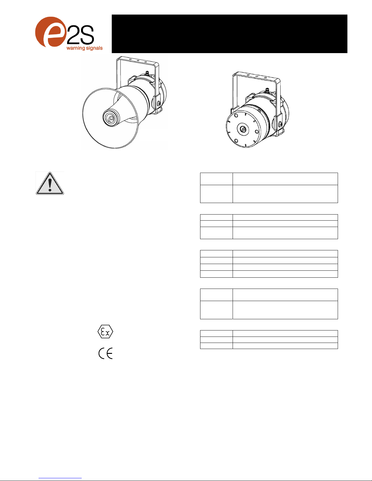
6) Location and Mounting
The location of the hootronic sounder should be made with
due regard to the area over which the warning signal must be
visible. They should only be fixed to services that can carry
the weight of the unit.
The BEx hootronic sounder should be secured to any flat
surface using the three 7mm fixing holes on the stainless
steel U shaped mounting bracket. See Figure 1. The required
angle can be achieved by loosening the two large bracket
screws in the side of the unit, which allow adjustment of the
hootronic sounder in steps of 18°. On completion of the
installation then two large bracket adjustment screws on the
side of the unit must be fully tightened to ensure that the unit
cannot move in service.
Fig. 1 Fixing Location for Hootronic sounder Flare
Fig. 1 Fixing Location for Hootronic sounder Radial
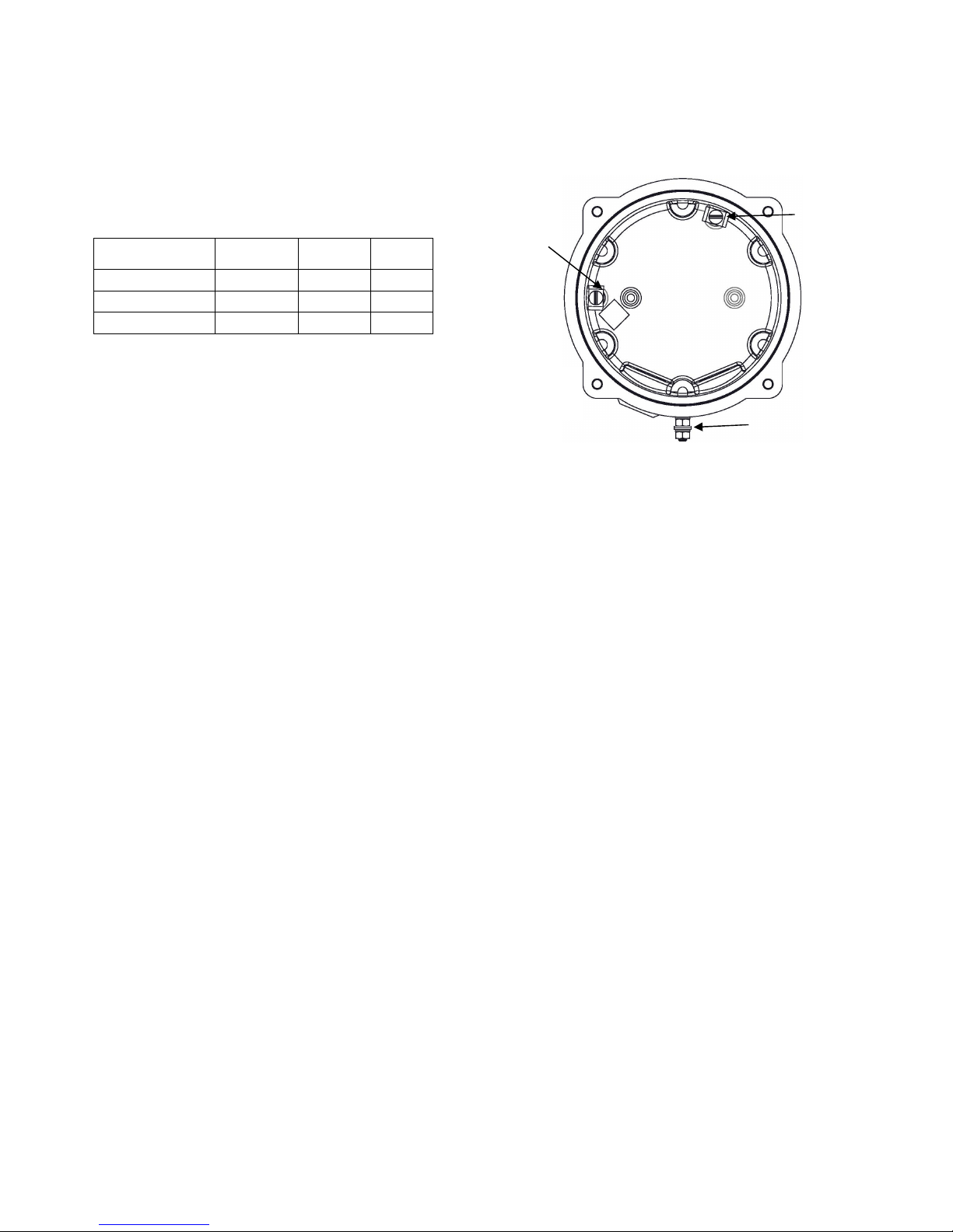
7) Access to the Flameproof Enclosure
To access the Ex d chamber, remove the four M6 hexagon
socket head screws and withdraw the flameproof cover taking
extreme care not to damage the flameproof joints in the
process. M6 cover screws are Class A4-80 stainless steel
and only screws of this category can be used for the
enclosure.
Fig. 2 Accessing the Explosion proof Enclosure.
On completion of the installation, the flameproof joints should
be inspected to ensure that they are clean and that they have
not been damaged during installation.
Check that the earth bonding wire between the two castings
is secure and the ‘O’ ring seal is in place. When replacing the
flameproof cover casting ensure that it is square with the
flameproof chamber casting before inserting. Carefully push
the cover in place allowing time for the air to be expelled.
Only after the cover is fully in place should the four M6
Stainless Steel A4-80 cover bolts and their spring washer be
inserted and tightened down. If the cover jams while it is
being inserted, carefully remove it and try again. Never use
the cover bolts to force the cover into position.
Warning – Hot surfaces. External surfaces
and internal components may be hot after
operation, take care when handling the
equipment.
Warning – High voltage may be present,
risk of electric shock. DO NOT open when
energised, disconnect power before
opening.
(Appropriate cable glands
to be customer su
pp
lied
)
Flameproof cover
M6 Cover
Screws
M6 Spring
Washer

_______________________________________________________________________________________________________________________________
European Safety Systems Ltd. Impress House, Mansell Road, Acton, London W3 7QH [email protected] Tel: +44 (0)208 743 8880
www.e-2-s.com Fax: +44 (0)208 740 4200
Document No. D201-00-031-IS Issue 1 18-08-16 Sheet 3 of 7
8) Power Supply Selection
It is important that a suitable power supply is used to run the
equipment. The power supply selected must have the
necessary capacity to provide the input current to all of the
units.
The following table shows the input current taken by the
various hootronic sounders and shows the maximum voltage
at which the hootronic sounders can be operated:
9) Selection of Cable. Cable Glands, Blanking
Elements & Adapters
When selecting the cable size, consideration must be given
to the input current that each unit draws (see table above),
the number of hootronic sounders on the line and the length
of the cable runs. The cable size selected must have the
necessary capacity to provide the input current to all of the
hootronic sounders connected to the line.
For ambient temperatures over +40ºC the cable entry
temperature may exceed +70ºC and therefore suitable heat
resisting cables and cable glands must be used, with a rated
service temperature of at least 110ºC
The dual cable gland entries have an M20 x 1.5 entry thread.
To maintain the ingress protection rating and mode of
protection, the cable entries must be fitted with suitably rated
ATEX / IECEx certified cable glands and/or suitably rated
ATEX / IECEx certified blanking devices during installation
according to EN / IEC60079-14.
If a high IP (Ingress Protection) rating is required then a
suitable sealing washer must be fitted under the cable glands
or blanking plugs.
For use in explosive dust atmospheres, a minimum ingress
protection rating of IP6X must be maintained.
The BEx hootronic sounder range can be supplied with the
following types of adapters:
M20 to ½” NPT
M20 to ¾” NPT
M20 to M25
It is important to note that stopping plugs cannot be fitted
onto adapters, only directly onto the M20 entries.
Any other adapters used must be suitably rated and ATEX /
IECEx certified adapters.
10) Earthing
Both AC and DC hootronic sounder units must be connected
to an earth. The units are provided with internal and external
earth terminals which are both located on the terminal
chamber section of the unit.
Fig. 3 Internal View of Cover
When using the internal earth terminal ensure that the
stainless steel M4 flat washer is between the incoming earth
wire and the enclosure.
Internal earthing connections should be made to the Internal
Earth terminal in the base of the housing using a ring crimp
terminal to secure the earth conductor under the earth clamp.
The earth conductor should be at least equal in size and
rating to the incoming power conductors.
External earthing connections should be made to the M5
earth stud, using a ring crimp terminal to secure the earth
conductor to the earth stud. The external earth conductor
should be at least 4mm² in size.
11) Cable Connections
Electrical connections are to be made into the terminal blocks
on the PCBA located in the flameproof enclosure. See
section 7 of this manual for access to the flameproof
enclosure.
Wires having a cross sectional area between 0.5 mm² to
2.5mm² can be connected to each terminal way. If an input
and output wire is required the 2-off Live/Neutral or +/-
terminals can be used. If fitting 2-off wires to one terminal
way the sum of the 2-off wires must be a maximum cross
sectional area of 2.5mm². Strip wires to 8mm. Wires may also
be fitted using ferrules. Terminal screws need to be tightened
down with a tightening torque of 0.45 Nm / 5 Lb-in. When
connecting wires to the terminals great care should be taken
to dress the wires so that when the cover is inserted into the
chamber the wires do not exert excess pressure on the
terminal blocks. This is particularly important when using
cables with large cross sectional areas such as 2.5mm².
Model No. Nominal I/P
Voltage
Input
Current
Max. I/P
Volts
BExH120DDC024 24Vdc 400mA 30V
BExH120DAC115 115Vac 130mA 126.5V
BExH120DAC230 230Vac 65mA 253V
External Earthing
Internal
Earthing
Internal
Bonding
Wire
Terminal
2-off M20
Cable
Entries

_______________________________________________________________________________________________________________________________
European Safety Systems Ltd. Impress House, Mansell Road, Acton, London W3 7QH [email protected] Tel: +44 (0)208 743 8880
www.e-2-s.com Fax: +44 (0)208 740 4200
Document No. D201-00-031-IS Issue 1 18-08-16 Sheet 4 of 7
12) AC Wiring
A 2-way terminal block is provided on the AC Hootronic
sounder for power. There are 1-off Live and 1-off Neutral
terminals in total. A 4-way terminal is provided for linking the
stop and the second and third stages. There are 1-off C/–ve,
1-off stage 2, 1-off stage 3 and 1-off stop terminals in total.
12.1 Wiring Diagrams
Fig. 4 BExH120 AC Simplified Block Diagram
12.2 Stage Switching
12.2.1 Units First Stage Tones
Stage one (S1) Operation
Simply connect the
supply voltage to the L
and N supply terminals,
(see fig. 4).
12.2.2 AC Units Second and Third Stage Tone
Selection
To select the second and third stage tones on the BExH120
AC hootronic sounder.
Stage two (S2) Operation
Power L and N, link the
Common-C and S2
terminal.
Header pins alters
stage 2 tone.
Stage three (S3) Operation
Power L and N, link the
Common-C and S3
terminals.
Header pins alters
stage 3 tone.
N L - 2 3 Stop
123
Fig. 5 AC Terminals
12.3 Stop Terminal
The user can remotely activate and deactivate the
BExH120D Hootronic AC sounder by switching a connection
between the “Stop” terminal to the “C/-” terminal whilst the
unit is powered. To achieve the “tail off” sound at switch off
the unit must remain powered.
13) DC Wiring
A 5-way terminal block is provided on the DC Hootronic
sounder. There are 1-off +ve, 1-off C/-ve, 1-off stage 2, 1-off
stage 3 and 1-off stop terminals in total.
13.1 Wiring Diagrams
Fig. 6a DC Simplified Block Diagram (negative switching)
Fig. 6b DC Simplified Block Diagram (positive switching)
Stage Headers
AC
Terminals
N
L
C/-
S2
S3
Stop
C/-

_______________________________________________________________________________________________________________________________
European Safety Systems Ltd. Impress House, Mansell Road, Acton, London W3 7QH [email protected] Tel: +44 (0)208 743 8880
www.e-2-s.com Fax: +44 (0)208 740 4200
Document No. D201-00-031-IS Issue 1 18-08-16 Sheet 5 of 7
13.2 Stage Switching
13.2.1 Units First Stage Tones
Stage one (S1) Operation
Simply connect the
supply voltage to the +
and - supply terminals,
(see fig. 6).
13.2.2 DC Units Second and Third Stage Tone
Selection
For units set up for –ve switching (default setting):
Stage two (S2) Operation
Power +ve and –ve, link
a -ve supply line to the
S2 terminal.
Header pins alters stage
2 tone.
Stage three (S3) Operation
Power +ve and –ve, link
a -ve supply line to the
S3 terminal.
Header pins alters stage
3 tone.
For units set up for +ve switching (refer to 13.3):
Stage two (S2) Operation
Power +ve and –ve, link
a +ve supply line to the
S2 terminal.
Header Pins alters stage
2 tone.
Stage three (S3) Operation
Power +ve and –ve, link
a +ve supply line to the
S3 terminal.
Header pins alters stage
3 tone.
+ - 2 3 Stop
123
S2 S3 Stop
+ve
-ve
Fig. 7 DC Terminals
13.3 Stage Switching Polarity (DC Units
Only)
The BExH120D DC hootronic sounders have the facility to
use either +ve or –ve switching to change the tone to the
second and third stages. Negative switching is the default
setting. For –ve switching connect the two headers on the
pcb to the left-hand (marked –ve) and centre pins. For +ve
switching connect the headers to the right hand (marked +ve)
and the centre pins. (Refer to Fig. 8)
+ - 2 3 Stop
123
S2 S3 Stop
+ve
-ve
Stage Headers Set for –ve Switching
Stage Headers Set for +ve Switching
Fig. 8 Stage Switching Polarity
13.3 Stop Terminal
The user can remotely activate and deactivate the
BExH120D Hootronic DC sounder by switching a connection
from the “Stop” terminal to the –ve or +ve supply lines,
depending on which switching mode is being used +ve or –ve
(see above) whilst the unit is powered. To achieve the “tail
off” sound at switch off the unit must remain powered.
Sound Headers
+
C/-
S2
S3
Stop
Stage
Headers
C/-
C/-

_______________________________________________________________________________________________________________________________
European Safety Systems Ltd. Impress House, Mansell Road, Acton, London W3 7QH [email protected] Tel: +44 (0)208 743 8880
www.e-2-s.com Fax: +44 (0)208 740 4200
Document No. D201-00-031-IS Issue 1 18-08-16 Sheet 6 of 7
Negative Switching Stop
Terminal Wiring
Positive Switching Stop Terminal
Wiring
13.4 Line Monitoring
On BExH120D Hootronic DC units, dc reverse line monitoring
can be used if required. The DC unit has a blocking diode
fitted in their supply input lines. An end of line monitoring
diode or an end of line monitoring resistor can be connected
across the +ve and –ve terminals. If an end of line resistor is
used it must have a minimum resistance value of 3k3 ohms
and a minimum wattage of 0.5 watts or a minimum resistance
value of 500 ohms and a min. wattage of 2 watts.
The resistor must be connected directly across the +ve and -
ve terminals as shown in the following drawing. The resistor
leads should be kept as short as possible.
+ - 2 3 Stop
123
S2 S3 Stop
+ve
-ve
Fig. 9 End of Line Resistor Placement
14) Settings
14.1 Sound Selection
The BExH120D Hootronic sounder has 5 different traditional
sounds that can be selected for the first stage alarm. The
sounders can then be switched to sound second and third
stage alarm sounds. The sounds are selected by pin headers
on the pcb for both DC and AC units. The sound table below
shows the pin header positions for the 5 sounds and which
sounds are available for the second and third stages.
The BExH120D Hootronic sounder has the facility to replicate
the “tail off” traditionally associated with these sounds when
generated by electro-mechanical devices. The switching is
achieved using the “Stop” terminal (see section 12 & 13).
See figure 5 for header location on AC units and Figure 7 for
header location on DC units.
Sound Selection Table
Stage 1 Description Stage 2 Stage 3 Header
Sound 1 Industrial Hooter Sound 3 Sound 5
Sound 2 High Frequency
Mechanical Siren Sound 1 Sound 5
Sound 3
Medium
Frequency
Mechanical Siren
Sound 1 Sound 5
Sound 4
Electro
Mechanical
Buzzer
Sound 2 Sound 5
Sound 5 Mechanical Bell Sound 1 Sound 2
14.2 Volume Control
The output level of the BEx hootronic sounder can be set by
adjusting the volume control potentiometer (see Fig 10). For
maximum output, set the potentiometer fully clockwise.
N L - 2 3 Stop
123
BExH120D AC
+ - 2 3 Stop
123
S2 S3 Stop
+ve
-ve
BExH120D DC
Fig. 10 Location of Volume Control Potentiometer
Warning - High noise levels above 85dB(A)
during operation. High levels of noise may
cause hearing loss, wear suitable ear
protection when equipment is in operation.
Volume
Control
Potentiometer
End of
Line
Resistor
Volume
Control
Potentiometer

_______________________________________________________________________________________________________________________________
European Safety Systems Ltd. Impress House, Mansell Road, Acton, London W3 7QH [email protected] Tel: +44 (0)208 743 8880
www.e-2-s.com Fax: +44 (0)208 740 4200
Document No. D201-00-031-IS Issue 1 18-08-16 Sheet 7 of 7
15) Maintenance, Overhaul & Repair
Maintenance, repair and overhaul of the equipment should
only be carried out by suitably qualified personnel in
accordance with the current relevant standards:
EN60079-19
IEC60079-19
Explosive atmospheres - Equipment repair,
overhaul and reclamation
EN 60079-17
IEC60079-17
Explosive atmospheres - Electrical
installations inspection and maintenance
To avoid a possible ELECTROSTACTIC CHARGE the unit
must only be cleaned with a damp cloth.
Units must not be opened while an explosive atmosphere is
present.
If opening the unit during maintenance operations a clean
environment must be maintained and any dust layer removed
prior to opening the unit.
Flameproof threaded joints and cemented joints are not
intended to be repaired.
This manual suits for next models
2
Table of contents
Other E2S Marine Equipment manuals

E2S
E2S GNExS2 User manual

E2S
E2S A105N APPELLO DC User manual

E2S
E2S E2xS1R User manual

E2S
E2S STExC1 User manual

E2S
E2S E2 S2R Series User manual

E2S
E2S BExCS110-05D-P User manual

E2S
E2S A112N User manual

E2S
E2S BE DCS110-L1D Series User manual

E2S
E2S BExS110D-SIL User manual

E2S
E2S AlertAlight AL105N Series User manual