manuals.online logo
Brands
  1. Home
  2. •
  3. Brands
  4. •
  5. Seakeeper
  6. •
  7. Marine Equipment
  8. •
  9. Seakeeper 18 User manual

Seakeeper 18 User manual

August 2020, Revision 2
INSTALLATION MANUAL
*THIS MANUAL ALSO COVERS THE SEAKEEPER 16 MODEL*
NOTE: THIS APPLIES TO SEAKEEPER 16 MODELS AFTER SERIAL No. 16-201-XXXX or LATER
INSTALLATION
MANUAL
Product:
Document #:
Rev:
SEAKEEPER 16 / 18
90549
2
SEAKEEPER 16 / 18
INSTALLATION MANUAL
AUGUST 2020
Contents:
Section 1 –Mechanical Installation & PC-120 Guide
Section 2 –Electrical Installation
Section 3 –Cooling Installation
Section 4 –Startup
Section 5 –Installation Checklist and Required Supplies
45310 ABELL HOUSE LANE, SUITE 350
CALIFORNIA, MARYLAND, 20619, U.S.A
PHONE: 410-326-1590
E-MAIL: contact@seakeeper.com
INSTALLATION
MANUAL
Product:
Document #:
Rev:
Page:
SEAKEEPER 16 / 18
90549
2
1 of 22
Section 1: MECHANICAL INSTALLATION
1.0 Introduction
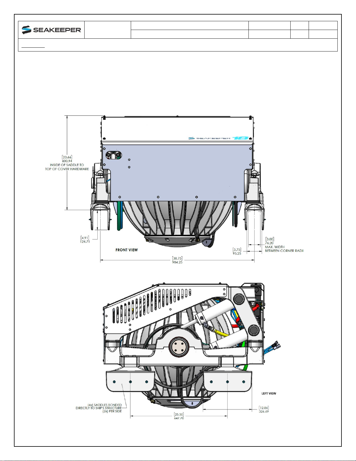
This document is intended to give details and guidance to a boat builder or equipment installer to
install the Seakeeper 16/18. The Seakeeper 16/18 can produce vertical loads up to 26.5KN
(5,965 lbs.), longitudinal loads up to 15.61KN (3,409 lbs.), and transvers loads of 2.22KN (500
lbs.) at each of the four mounts. Careful consideration should be given to foundation design to
insure it is capable of transferring these loads into the hull. These loads do NOT include vessel
motion accelerations, such as vertical slam loads which can be significant for high speed vessels
and vary based upon the longitudinal location.
There are two methods of installing the Seakeeper 16/18:
1) Bolt-In Installation
2) Bond-In (Saddle) Installation
It is assumed that the installer is familiar with bonding using high strength adhesives or
mechanical fasteners to marine structures and has performedstructural analysis to assure
the structure to which the Seakeeper mounts can properly transfer the loads the Seakeeper
creates into the hull structure. If the installer has any doubt about the ability of the
structure to transfer the loads to the hull, then a licensed naval architect or marine
engineer should be contacted to do a structural analysis.
The installer should review the following list of reference drawings to ensure the installation
procedure is fully understood.
Reference Drawings
90243 Seakeeper 16 Hardware Scope of Supply
90538 Seakeeper 18 Hardware Scope of Supply
90544 Seakeeper 16/18 Bolt-In Installation Guide
90545 Seakeeper 16/18 Bond-In Installation Guide
90540 Seakeeper 16/18 Cooling Water Schematic
90282 Seakeeper 16/12HD/18 Installation Template Kit
90539 Seakeeper 16/18 Cable Block Diagram
90548 Seakeeper 16/18 Bolt-in Kit
90547 Seakeeper 16/18 Bond-in Kit
INSTALLATION
MANUAL
Product:
Document #:
Rev:
Page:
SEAKEEPER 16 / 18
90549
2
2 of 22
Section 1: MECHANICAL INSTALLATION
1.1 Precautions
•The Seakeeper must only be lifted from the supplied lifting eyes (See Section 1.4), shown
in Figure 1.
•The Seakeeper flywheel is supported by precision bearings. DO NOT drop or impart
mechanical shock to the Seakeeper assembly when lifting or unpacking, as damage to
bearings could result.
•While handling / installing the Seakeeper assembly, protect exposed hydraulic brake
cylinder rods (See Figure 1) from scratches or damage as this could lead to premature
seal failure and oil leaks.
•While handling / installing the Seakeeper assembly, do not allow electrical fittings that exit
bottom of the Seakeeper enclosure to come in contact with any surface or object as this
could damage the fittings and potentially affect the vacuum integrity of the enclosure.
•Exercise care to protect the painted finish as damage to the finish could lead to early
appearance degradation of the installed Seakeeper.
FIGURE 1 –SEAKEEPER 16/18
INSTALLATION
MANUAL
Product:
Document #:
Rev:
Page:
SEAKEEPER 16 / 18
90549
2
3 of 22
Section 1: MECHANICAL INSTALLATION
1.2 Selection of Seakeeper Installation Location
Selection of mounting location of the Seakeeper should consider the following desirable
features:
The Seakeeper should be installed at, or aft of, amidships to minimize
high vertical acceleration loadings due to hull/wave impacts during
operation at high speed or in large waves. If the only possible Seakeeper
location is forward of amidships then the installer should have Seakeeper
review the installation location prior to finalizing the design.
•Overhead access or sufficient clearance for removal / re-installation of the
Seakeeper for overhaul in future years.
•The Seakeeper should be installed in a dry space to minimize effects of corrosion.
•Clearance forall recommended scheduled maintenanceand anyrepairs isnecessary (see
Figure 2).
INSTALLATION
MANUAL
Product:
Document #:
Rev:
Page:
SEAKEEPER 16 / 18
90549
2
4 of 22
Section 1: MECHANICAL INSTALLATION
INSTALLATION
MANUAL
Product:
Document #:
Rev:
Page:
SEAKEEPER 16 / 18
90549
2
5 of 22
Section 1: MECHANICAL INSTALLATION
VIEWS SHOWING RECOMMENDED CLEARANCES AROUND THE SEAKEEPER FOR USE OF HAND TOOLS, EASE
OF MAINTENANCE, INSTALLATION AND PROPER OPERATION.
FIGURE 2 –INSTALLED SEAKEEPER CLEARANCE CONSIDERATIONS
FIGURE 3 –TRANSVERSE BEAMS CLEARANCE CONSIDERATIONS
INSTALLATION
MANUAL
Product:
Document #:
Rev:
Page:
SEAKEEPER 16 / 18
90549
2
6 of 22
Section 1: MECHANICAL INSTALLATION
Refer to Figure 3 for recommended clearances to transverse beams. If a transverse beam is
located under the forward brace, it must be 1” (25 mm) from the edge of the Seakeeper to
provide the necessary clearance for the swing of the motor power cable during the Seakeeper’s
precession. Clearances aft of the Seakeeper are shown to provide access for maintenance.
Safety
There is a large torque about the gimbal axis when the Seakeeper is precessing.
Seakeeper cover panels are provided to prevent personnel or equipment from contacting
the Seakeeper while it is in operation. These covers should not be stepped on or have
anything placed on top. The covers should always be in place during operation. If it is
ever necessary to access the Seakeeper while the flywheel is spinning, the Seakeeper
must be locked at the display to stop the Seakeeper from precessing. Seakeeper regular
scheduled maintenance should not be attempted unless the Seakeeper is locked and the
flywheel has stopped spinning.
The Seakeeper should be treated with the same respect one gives a high-speed rotating
propeller or engine shaft.
Noise/Soundproofing
Seakeeper noise has been measured under steady state conditions (no wave load) in
Seakeeper's lab and in our test boat. The steady state noise is typically in the range of 66-68 dB
un-weighted. As the frequencies emitting the highest sound pressures are low (like other marine
machinery), it is recommended that the Seakeeper be installed in a machinery space that is
already treated with soundproofing.
INSTALLATION
MANUAL
Product:
Document #:
Rev:
Page:
SEAKEEPER 16 / 18
90549
2
7 of 22
Section 1: MECHANICAL INSTALLATION
1.3 Selection of Installation Method
The Seakeeper 16/18 can be affixed to the hull structure using two methods:
1) Bolt-In installation or
2) Bond-In (Saddle) installation. See figures below.
OPTION 1- DIRECT FASTENING OF SEAKEEPER FOUNDATION TO SHIPS STRUCTURE
INSTALLATION
MANUAL
Product:
Document #:
Rev:
Page:
SEAKEEPER 16 / 18
90549
2
8 of 22
Section 1: MECHANICAL INSTALLATION
Option 1 would be applied when a metal structure or metal reinforce fiberglass stringer is
available for attachment. The foundation would fasten directly to hull structure using isolation
gaskets and 16x M14X2.0 fasteners. Depending on the structural arrangement to which the
Seakeeper is fastened, blind threaded holes or thru-bolting can be utilized.
OPTION 2- SADDLE INSTALLATION (4 PLACES)
INSTALLATION
MANUAL
Product:
Document #:
Rev:
Page:
SEAKEEPER 16 / 18
90549
2
9 of 22
Section 1: MECHANICAL INSTALLATION
Option 2 would be most commonly used on a hull constructed of glass reinforced plastic (GRP)
or fiberglass. For this option, four 12.9-inch (327 mm) long x 4.9-inch (125 mm) wide x 6.7-inch
(170 mm) height saddles are bonded to properly spaced and prepared structural members that
are an integral part of the hull structure. Seakeeper recommends using a structural adhesive
with a lap shear strength of 2000 psi (13.8 MPa) or greater. Careful consideration should be
exercised by the installer while selecting the appropriate adhesive. Compatibility with the
Seakeeper’s cast aluminum A356-T6 saddles, hull structure and pot life are three important
factors to consider. Proper surface preparation in accordance with adhesive manufacturer’s
recommendations prior to installation is very important. Recommended adhesives can be found
in Seakeeper Technical Bulletin 90382 –Adhesive Recommendations.
1.4 Unpacking Crate
1) Reference Seakeeper Drawing No. 90243, Seakeeper 16 Hardware Scope of Supply and
90538, Seakeeper 18 Hardware Scope of Supply for items that ship with the
corresponding Seakeeper model.
2) Remove electrical components, cables, and misc. items and set aside.
3) Remove packing materials that secure Seakeeper assembly inside the crate.
4) Remove top and angled face cover panels to access lifting eyes.
5) Attach spreader bar (Seakeeper #80061) to the two lifting eyes located on the top of the
Seakeeper enclosure. Stay clear of any other parts on the Seakeeper. The Seakeeper
weighs 1030 kg (2,270 lbs.). See Figure 4 below.
6) Remove lag bolts from the Seakeeper foundation and prepare to lift the Seakeeper from
the crate.
FIGURE 4 –LIFTING ARRANGEMENT
Spreader Bar
Lifting Eyes
INSTALLATION
MANUAL
Product:
Document #:
Rev:
Page:
SEAKEEPER 16 / 18
90549
2
10 of 22
Section 1: MECHANICAL INSTALLATION
1.5Bolt-In Installation
1.5.1 Check and Preparation of Hull Structure
Refer to Seakeeper Drawing No. 90544, Seakeeper 16/18 Installation Details –Bolt in
Method. Important dimensional and load information is given in this drawing that will impact the
design details of the structure that will receive the Seakeeper. It is assumed that a proper
structural analysis has been performed for the hull structure to which the Seakeeper will be
fastened to ensure proper strength margins for the loads the Seakeeper will create during
operation. Seakeeper recommends a safety factor of 3.0.
The hull structure supporting the Seakeeper should be arranged so the Seakeeper is parallel to
the waterline. In addition, the four areas on top of the beams on which the feet of the
Seakeeper foundation and isolation gaskets will rest need to be co-planar within .06” (1.5
mm) to minimize potential distortion of Seakeeper support frame when installed. The
isolation gaskets are only used on dissimilar metal to metal contact.
Seakeeper provides an installation template kit, P/N 90282, which contains four plates that mimic
the mating surfaces of the four feet located on the Seakeeper’s foundation. These plates have 4
holes located at the same centers as the mounting holes on the Seakeeper. The fixture locates
the hole patterns at the proper spacing both in the fore-aft direction and the port-starboard
direction, see Figures 5. Once assembled, the fixture can be used to check clearances and
alignment of the hull structure.
Note: Do NOT use theinstallation fixture to establish the Seakeeperenvelope dimensions.
Refer to Drawing No. 90544 for envelope dimensions. A 3-D model of the Seakeeper is
available on the Seakeeper website (www.seakeeper.com) to aid in designing the
Seakeeper foundation and the space around the Seakeeper.
NOTE: MAKE SURE NO OBSTRUCTIONS FROM THE HULL STRUCTURE CAN BE SEEN WITHIN THE INSIDE
OF THE INSTALLATION TEMPLATE KIT (INSIDE THE MARKED RED LINES). REFERENCE SEAKEEPER
DRAWING NO. 90544.
FIGURE 5 –INSTALLATION FIXTURE, 90282
INSTALLATION
MANUAL
Product:
Document #:
Rev:
Page:
SEAKEEPER 16 / 18
90549
2
11 of 22
Section 1: MECHANICAL INSTALLATION
CAUTION: Tight clearances from cable guide bands to hull structure. See above figure
for dimensions and reference Seakeeper drawing NO. 90544 for complete Seakeeper
16/18 envelope.
INSTALLATION
MANUAL
Product:
Document #:
Rev:
Page:
SEAKEEPER 16 / 18
90549
2
12 of 22
Section 1: MECHANICAL INSTALLATION
1.5.2 Transfer of Holes to Boat Structure
1) Lower assembled fixture onto
hull structure.
2) The four areas where the
feet of the Seakeeper will
rest should be coplanar to
within .06” (1.5mm). See
Figure 10.
3) Align fixture in desired location
and transfer holes from fixture
plate to the hull structure.
Note that holes in fixture plate
are ø0.55 (14 mm).
4) Remove fixture and drill and tap
M14X2.0 holes in hull structure at
marked locations to mate with
holes in the Seakeeper
foundation. Take special care to
drill perpendicular to mounting
surface. Remove any impeding
obstructions.
INSTALLATION
MANUAL
Product:
Document #:
Rev:
Page:
SEAKEEPER 16 / 18
90549
2
13 of 22
Section 1: MECHANICAL INSTALLATION
1.5.3 Installation of Seakeeper
1) Locate and position 4 isolation
gaskets onto foundation beams (for
metal to metal contact only).
NOTE: Sealant or caulk is
recommended to be applied. Apply
a small bead (approximately 4mm
wide) of sealant (silicone or caulk)
between both mating surfaces of
each isolation gasket where it
contacts the beam and the
Seakeeper. This will prevent water
from wicking between the parts and
setting up corrosion. Check
isolation gasket alignment by test
fitting bolts without any
obstructions.
2) Lower Seakeeper into position onto
the hull foundation beams and align
over drilled holes.
3) Install Seakeeper supplied M14
fasteners–Apply a moderate coat of
marine anti-seize (e.g., SAF-T-EZE
Nickel Grade Anti-Seize, SBT-4N or
equivalent) to the threads of each
bolt and include a small bead of
sealant under each bolt head before
installation.
4) Torque all fasteners to 100 ft-lbs.
(136 N-m).
5) Proceed to electrical and cooling
portion of the installation.
INSTALLATION
MANUAL
Product:
Document #:
Rev:
Page:
SEAKEEPER 16 / 18
90549
2
14 of 22
Section 1: MECHANICAL INSTALLATION
1.6 Saddle Installation
Seakeeper recommends a slow curing, non-sagging structural adhesive for bonding the saddles
to the GRP hull structure. Such an adhesive is Plexus MA590 which is a two-part methacrylate
adhesive. Details of the bonding procedure in this manual will involve the Plexus MA590 product,
but that should not exclude other suitable adhesives the installer chooses to use.See Sheet 5 of
Seakeeper drawing No. 90545 for loads information and recommended adhesive
properties.
1.6.1 Initial Check and Preparation of Hull Structure
Refer to Seakeeper Drawing No. 90545, Seakeeper 16/18 Installation Details –Bond-In
Method. Important dimensional and load information is given in this drawing that will impact the
design details of the structure that will receive the Seakeeper as well as selection of the adhesive
to bond the Seakeeper into the hull.
The foundation “saddles” of the Seakeeper are designed to be bonded directly to the composite
hull structure of the vessel to effectively distribute Seakeeper loads. A complete bond is
required between the inside surface of the saddles and the hull structure. An estimate of
adhesive volume required should be calculated for each installation based on gaps between
saddles and structural members. There is some adhesive waste as a part of the process, so a
good rule of thumb is to purchase up to 50% more adhesive than estimated volume to ensure a
complete bond. Depending on conditions and adhesive used, two workers may be required to
apply the adhesive at the same time to finish the installation before the adhesive starts to cure.
To aid in determining the quantity of adhesive required, the interior surface area (bonding
surfaces) of each saddle is 164 in2(1058 cm2) for a total bonded surface area for all four saddles
of 656 in2(4232 cm2).
The hull structure supporting the Seakeeper should be arranged so the Seakeeper is parallel to
the waterline. The four areas on top of the beams that the saddles will bond to need to be
co-planar within .13” inches (3 mm) for consistent adhesive bond gap. In addition, the four
areas on top of the saddles on which the feet of the Seakeeper foundation will rest need to
be co-planar within .06” (1.5 mm) to minimize potential distortion of Seakeeper support
frame when installed.
Note that any paint or gelcoat present in bond area should be removed so that adhesive
will bond directly to laminate fibers and resin.
Seakeeper provides an installation fixture template, P/N 90282 that locates the saddles at the
proper spacing both in the fore-aft direction and the port-starboard direction. See Figures 6, 7 &
8 below. Once assembled with the provided saddle fittings, the fixture can be used to check
clearances and alignment of the hull structure. The fixture will allow the builder / installer to lay-
up and adjust the foundation dimensions to create a low-clearance fit between the Seakeeper
foundation saddles and the hull structure. Shear strength of the adhesive will be maximized if the
cured thickness between the vessel structure and Seakeeper saddles is at the thinner end of the
adhesive manufacturer’s recommended range. Therefore, the fixture should be used to confirm
INSTALLATION
MANUAL
Product:
Document #:
Rev:
Page:
SEAKEEPER 16 / 18
90549
2
15 of 22
Section 1: MECHANICAL INSTALLATION
that the overall dimensions of the foundations are square and level and that the adhesive gap is
within Seakeeper’s recommended range of 1 to 3mm (.04” to .13”).
Note: Do NOT use the installation fixture to establish Seakeeper envelope dimensions.
Refer to Drawing No. 90545 for envelope dimensions. A 3-D model of the Seakeeper is
available on the Seakeeper website (www.seakeeper.com) to aid in designing the
Seakeeper foundation and the space around the Seakeeper.
NOTE: MAKE SURE NO OBSTRUCTIONS FROM THE HULL STRUCTURE CAN BE SEEN WITHIN THE INSIDE
OF THE INSTALLATION TEMPLATE KIT (INSIDE THE MARKED RED LINES). REFERENCE SEAKEEPER
DRAWING NO. 90545.
FIGURE 6 –EXPLODED VIEW OF SADDLE INSTALLATION FIXTURE
INSTALLATION
MANUAL
Product:
Document #:
Rev:
Page:
SEAKEEPER 16 / 18
90549
2
16 of 22
Section 1: MECHANICAL INSTALLATION
FIGURE 7 –SADDLE INSTALLATION FIXTURE ON NOTIONAL HULL STRUCTURE
1.6.2 Fiberglass Hull Preparation
INSTALLATION
MANUAL
Product:
Document #:
Rev:
Page:
SEAKEEPER 16 / 18
90549
2
17 of 22
Section 1: MECHANICAL INSTALLATION
1) Position installation fixture (Fig 8) on hull girders noting recommended clearances for
maintenance from Figure 2. Check that the screws fastening the saddles to the installation
fixture are tight (Fig 6).
2) Mask hull area (Fig 9) around foundation saddles for easy clean-up and to create outline
of surface area to receive adhesive as (Fig 8). Ensure that the bond gap is within
Seakeeper’s recommended thickness, or 3mm if using Plexus MA590.
3) Raise fixture clear of foundation. Check all four mounting areas are co-planar to within
.13” (3 mm) to each other, as well as parallel to the water line plane, as shown in Fig 8.
FIGURE 8 - INSTALLING FIXTURE ON HULL
FIGURE 9 - MASKING PERIMETER OF SADDLES
INSTALLATION
MANUAL
Product:
Document #:
Rev:
Page:
SEAKEEPER 16 / 18
90549
2
18 of 22
Section 1: MECHANICAL INSTALLATION
4) Remove any paint or gelcoat from bond surfaces so that adhesive will bond directly to
laminate fibers and resin as shown in Figure 8.
5) Thoroughly sand hull girder bond surfaces with 80 grit sandpaper. (IMPORTANT –
BOND STRENGTH MAY BE REDUCED IF THIS STEP IS SKIPPED.)
6) Wipe surfaces clean from dust with alcohol or acetone using new paper towels, not shop
rags.
7) Re-position installation fixture on girders and double-check that the adhesive gap is within
the adhesive manufacturer’s maximum recommended thickness. Seakeeperrecommends
a maximum gap of 3mm if using Plexus MA590.
Note if bonding saddles to a metal structure, contact Seakeeper for
hull preparation instructions.
FIGURE 10 –COPLANAR PROPERTIES OF FOUNDATION

Other manuals for 18

1

This manual suits for next models

1

Other Seakeeper Marine Equipment manuals

Seakeeper 7000 GYRO User manual

Seakeeper

Seakeeper 7000 GYRO User manual

Seakeeper 6 User manual

Seakeeper

Seakeeper 6 User manual

Seakeeper 9 GYRO User manual

Seakeeper

Seakeeper 9 GYRO User manual

Seakeeper 9 User manual

Seakeeper

Seakeeper 9 User manual

Seakeeper 7HD User manual

Seakeeper

Seakeeper 7HD User manual

Popular Marine Equipment manuals by other brands

Side-Power Stabilizer Operation and user's guide

Side-Power

Side-Power Stabilizer Operation and user's guide

Furuno FI-501 Brochure & specs

Furuno

Furuno FI-501 Brochure & specs

VEXILAR FL-18 owner's manual

VEXILAR

VEXILAR FL-18 owner's manual

knudsen Chirp 3212 quick start guide

knudsen

knudsen Chirp 3212 quick start guide

Fulleon ASSERTA quick start guide

Fulleon

Fulleon ASSERTA quick start guide

ADVANSEA Speed s400 user manual

ADVANSEA

ADVANSEA Speed s400 user manual

Furuno CSH-5 MARK-2 Operator's guide

Furuno

Furuno CSH-5 MARK-2 Operator's guide

Jensen MWR150 Installation and operation instruction

Jensen

Jensen MWR150 Installation and operation instruction

TRIGA TR-B200SR-WH Installation and maintenance instructions

TRIGA

TRIGA TR-B200SR-WH Installation and maintenance instructions

Raymarine EV-100 installation instructions

Raymarine

Raymarine EV-100 installation instructions

Black cat BATTLE SOUNDER RECEIVER manual

Black cat

Black cat BATTLE SOUNDER RECEIVER manual

ProFurl Nex 0.9 installation manual

ProFurl

ProFurl Nex 0.9 installation manual

Raymarine P70 User reference

Raymarine

Raymarine P70 User reference

Selden Furlex 200 S Assembly manual

Selden

Selden Furlex 200 S Assembly manual

Kongsberg EM 710 Maintenance manual

Kongsberg

Kongsberg EM 710 Maintenance manual

Humminbird 700 series Installation & operation manual

Humminbird

Humminbird 700 series Installation & operation manual

Humminbird Side Imaging Transducer manual

Humminbird

Humminbird Side Imaging Transducer manual

Furuno GP-1650DF Operator's manual

Furuno

Furuno GP-1650DF Operator's manual

manuals.online logo
manuals.online logoBrands
  • About & Mission
  • Contact us
  • Privacy Policy
  • Terms and Conditions

Copyright 2025 Manuals.Online. All Rights Reserved.