manuals.online logo
Brands
  1. Home
  2. •
  3. Brands
  4. •
  5. Sealey
  6. •
  7. Batteries Charger
  8. •
  9. Sealey CHARGETRONIC 12 User manual

Sealey CHARGETRONIC 12 User manual

1.1. ELECTRICAL SAFETY
 WARNING! It is the user’s responsibility to read, understand and comply with the following:
You must check all electrical equipment and appliances to ensure they are safe before using. You must inspect power supply leads, plugs and all electrical
connections for wear or damage. You must ensure the risk of electric shock is minimised by the installation of appropriate safety devices. An RCCB (Residual
Current Circuit Breaker) should be incorporated in the main distribution board. We also recommend that an RCD (Residual Current Device) is used with all
electrical products. It is particularly important to use an RCD with portable products that are plugged into an electrical supply not protected by an RCCB. If in
doubt consult a qualified electrician. You may obtain a Residual Current Device by contacting your Sealey dealer. You must also read and understand the fol
lowing instructions concerning electrical safety.
1.1.1. The Electricity At Work Act 1989 requires all portable electrical appliances, if used on business premises, to be tested by
a qualified electrician, at least once a year, using a Portable Appliance Tester (PAT).
1.1.2. The Health & Safety at Work Act 1974 makes owners of electrical appliances responsible for the safe condition of those appliances and the safety of
appliance operators. If in any doubt about electrical safety, contact a qualified electrician.
1.1.3. Ensure the insulation on all cables and the product itself is safe before connecting to the mains power supply.
See 1.1.1. & 1.1.2. above and use a Portable Appliance Tester (PAT).
1.1.4. Ensure that cables are always protected against short circuit and overload.
1.1.5. Regularly inspect power supply, leads and plugs for wear or damage and also power connections to ensure
that none is loose.
1.1.6. Important: Ensure the voltage marked on the product is the same as the electrical power supply to be used and
check that plugs are fitted with the correct capacity fuse. A 13 amp plug may require a fuse smaller than 13 amps
for certain products - see fuse rating at right.
1.1.7. DO NOT pull or carry the appliance by its power supply lead or by the output leads.
1.1.8. DO NOT pull power plugs from sockets by the power cable.
1.1.9. DO NOT use worn or damage leads, plugs or connections. Immediately replace or have repaired by a qualified
electrician. Where a U.K. 3 pin plug with ASTA/BS approval is fitted, in case of damage, cut off and fit a new plug
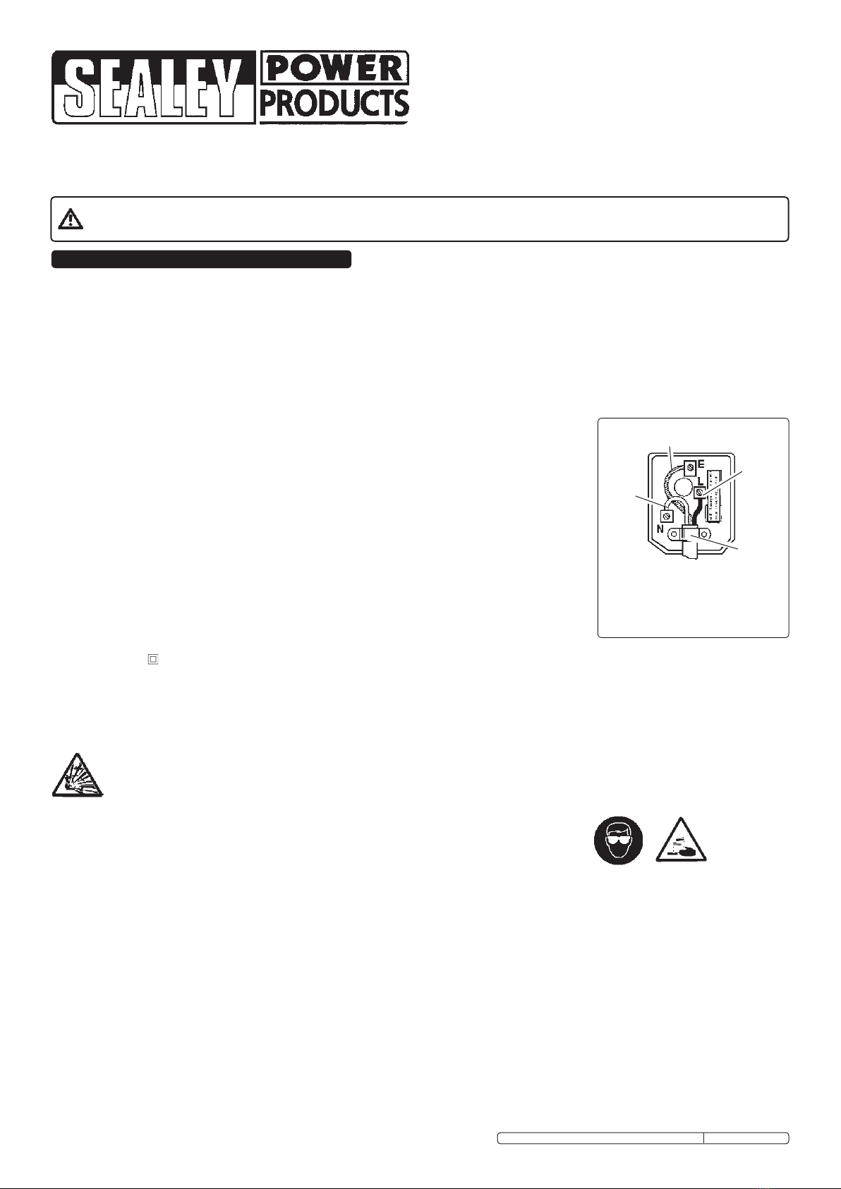
according to the following instructions (discard old plug safely).
(UK only - see diagram at right). Ensure the unit is correctly earthed via a three-pin plug.
a) Connect the GREEN/YELLOW earth wire to the earth terminal ‘E’.
b) Connect the BROWN live wire to the live terminal ‘L’.
c) Connect the BLUE neutral wire to the neutral terminal ‘N’.
d) After wiring, check that there are no bare wires, that all wires have been correctly connected,
that the cable external insulation extends beyond the cable restraint and that the restraint is tight.
Double insulated products are fitted with live (BROWN) and neutral (BLUE) wires only. Double insulated products are always marked with
this symbol . To re-wire, connect the brown & blue wires as indicated above. DO NOT connect the brown or blue wires to the earth terminal.
1.1.10. NOTE: If this product requires more than a 13 amp electrical supply, then NO plug is fitted. You must therefore contact a qualified electrician to ensure that
a 30 amp fused supply is available. We recommend you discuss the installation of a industrial round pin plug and socket with your electrician.
1.1.11. Cable extension reels. When a cable extension reel is used it should be fully unwound before connection. A cable reel with an RCD
fitted is recommended since any product which is plugged into the cable reel will be protected. The section of the cores in the cable
is important and should be at least 1.5mm², but to be absolutely sure that the capacity of the cable reel is
suitable for this product and for others that may be used in the other output sockets, we recommend the use of 2.5mm² section.
FUSE RATING
THE PLUG FITTED TO THIS
PRODUCT MUST BE EQUIPPED
WITH A 3 AMP FUSE
1.2. PERSONAL PRECAUTIONS
Ensure there is another person within hearing range of your voice and close enough to come to your aid,
should a problem arise when working near a lead-acid battery.
Wear safety eye protection and protective clothing. Avoid touching eyes while working near battery.
Have fresh water and soap nearby in case battery acid contacts skin, clothing, or eyes.
Wash immediately with soap and water if battery acid contacts skin or clothing. If acid enters eye, flush eye immediately with cool, clean running water for at least
15 minutes and seek immediate medical attention.
Remove personal metallic items such as rings, bracelets, necklaces and watches. A lead-acid battery can produce a short-circuit current which is high enough to
weld a ring or the like to metal, which would cause severe burns.
Ensure hands, clothing (especially belts) are clear of fan blades and other moving or hot parts of engine, remove ties and contain long hair.
 DO NOT smoke or allow a spark or flame in the vicinity of battery or engine.
1.3. GENERAL SAFETY INSTRUCTIONS
Familiarise yourself with the application and limitations of the charger as well as the potential hazards. Also refer to the vehicle manufacturer’s hand book.
IF IN ANY DOUBT CONSULT AN ELECTRICIAN.
Ensure the charger is in good order and condition before use. If in any doubt do not use the unit and contact an electrician.
Only use recommended attachments and parts. To use non-recommended items may be dangerous and will invalidate your warranty.
Use the charger in the upright position only and ensure it is placed on a stable surface which will adequately support its weight.
Ensure the charger is disconnected from the mains supply before attaching/detaching the power clamps to/from the battery.
Keep tools and other items away from the engine and ensure you can see the battery and working parts of engine clearly.
Ensure the output voltage of the charger is, or is set to, the same voltage as the battery.
If battery has caps to access the battery fluid, remove the caps and check the fluid level before connecting the power clamps. If necessary top-up the battery with
distilled water by referring to the battery manufacturer’s instructions (Apply the personal safety precautions described in part 1.2).
If the charger receives a sharp knock or blow the unit must be checked by a qualified service agent before using.
INSTRUCTIONS FOR:
12V & 12/24V ELECTRONIC
BATTERY CHARGERS
Thank you for purchasing a Sealey product. Manufactured to a high standard this product will, if used according to these instructions and properly maintained, give you
years of trouble free performance.
1. SAFETY INSTRUCTIONS
IMPORTANT: PLEASE READ THESE INSTRUCTIONS CAREFULLY. NOTE THE SAFE OPERATIONAL REQUIREMENTS, WARNINGS & CAUTIONS.
USE THE PRODUCT CORRECTLY AND WITH CARE FOR THE PURPOSE FOR WHICH IT IS INTENDED. FAILURE TO DO SO MAY CAUSE DAMAGE
AND/OR PERSONAL INJURY AND WILL INVALIDATE THE WARRANTY. PLEASE KEEP INSTRUCTIONS SAFE FOR FUTURE USE.
Yellow & Green
Earth Wire
Cable
Restraint
Brown
Live
Wire
DANGER! BE AWARE, LEAD-ACID BATTERIES GENERATE EXPLOSIVE GASES DURING NORMAL BATTERY OPERATION. FOR THIS REASON,
IT IS VERY IMPORTANT TO READ AND FOLLOW THESE INSTRUCTIONS CAREFULLY, EACH TIME YOU USE THE CHARGING EQUIPMENT.
Follow these instructions and those published by the battery and vehicle manufacturers, and the maker of any equipment you intend to use in the vicinity
of the battery. Remember to review warning marks on all products and on engines.
MODELS: CHARGETRONIC 12 & CHARGETRONIC 12/24.V2
Blue
Neutral
Wire
Original Language Version CHARGETRONIC12, CHARGETRONIC12/24.V2 Issue: 2 - 04/03/10
The Chargetronic 12 and Chargetronic 12/24.V2 are battery chargers with 230 voltAC input and electronically monitored outputs, respectively 12 volt DC and switchable 12/24
volt DC. The units are intended for charging free-electrolyte lead-acid batteries as used in motor vehicles (petrol and diesel), motorcycles and boats. ,
If the battery terminals are corroded or dirty clean them before attaching the power clamps.
Keep children and unauthorised persons away from the working area.
 DO NOT dis-assemble the charger for any reason. The charger must only be checked by qualified service personnel.
 DO NOT try to charge a non-rechargeable battery.
 DO NOT try to start engine when charger is connected to battery.
 DO NOT try to charge battery if fluid is frozen.
WARNING! To prevent the risk of sparking, short circuit and possible explosion DO NOTdrop metal tools in the battery area, or allow them to touch the battery terminals.
 DO NOT allow power clamps to touch each other or to make contact with any metallic part of the vehicle.
DO NOT cross connect power leads from charger to battery. Ensure positive (+/RED) is to positive and negative (-/BLACK) is to negative. If symbols cannot be
distinguished, remember that the negative terminal is the one directly connected to the vehicle bodywork.
DO NOT pull the cables or clamps from the battery terminals.
DO NOT use the charger outdoors, or in damp, or wet locations and DO NOT operate within the vicinity of flammable liquids or gases.
 DO NOT use charger inside vehicle or inside engine compartment.
 Ensure there is effective ventilation to prevent a build-up of explosive gases, and do not cover or obstruct charger ventilation louvres.
DO NOT use the charger for a task for which it is not designed.
WARNING! DO NOT simultaneously charge batteries of different capacities or discharge levels.
WARNING! If a fuse blows, ensure it is replaced with an identical fuse type and rating. Use only Sealey genuine parts.
 When not in use, store the charger carefully in a safe, dry, childproof location.
3. OPERATION
 WARNING! Ensure you read, understand and apply the safety and operational instructions before connecting the charger power clamps to the battery. Only when
you are sure that you understand the procedures is it safe to proceed with the actual charging process.
3.1. Status indicators
Four LEDs on the charger front panel indicate status:
Red LED -Clamps have been incorrectly connected to battery - disconnect charger from mains supply and reconnect red clamp to positive battery terminal,
black clamp to negative terminal.
Yellow LED - Battery is being charged but the charging is not complete.
Upper Green LED - Battery is fully charged - disconnect charger from mains supply and then from battery.
Lower green LED - Charger is connected to mains supply
3.2. Output voltage switch - Chargetronic 12/24.V2 only
A rocker switch on the front panel allows selection of either 12 or 24 volt output to suit the battery which is to be charged. The selection should be made prior
to connecting the clamps to the battery.
3.3. Output fuse
The output fuse is located on the front panel and a spare fuse is clipped into the rear of the charger.
3.4. Battery charging
3.4.1. Establish the battery voltage (noting that two 12V batteries in series will require a 24V charge).
3.4.2. Select appropriate output voltage - Chargetronic 12/24.V2 only.
3.4.3. Remove battery caps, if possible.
3.4.4. Connect power clamps to the battery terminals, ensuring correct polarity.
3.4.5. Connect charger to mains power supply, switch on and ensure lower green LED is illuminated. Confirm that red LED is not illuminated, indicating correct
connections, and that yellow LED is illuminated, indicating that battery is being charged.
3.4.6. When upper green LED illuminates, indicating that battery is fully charged, disconnect charger from the mains supply and only then remove clamps from
the battery terminals.
3.4.7. Carefully wipe any spillage of acid from the battery top and replace battery caps, if removed.
3.4.8. FOR A VERY FLAT BATTERY, DISCONNECT CABLES FROM BATTERY TERMINALS AND ALLOW BATTERY TO REST FOR 30 MINUTES BEFORE
ATTEMPTING TO CHARGE. REMEMBER TO PROVIDE A BACK-UP SUPPLY FOR THE VEHICLE WHEN DOING THIS IN ORDER TO PREVENT DAMAGE
TO ON-BOARD ELECTRONICS. CHECK SEALEY MODEL VS207 FOR THIS FUNCTION.
WARNING! Ensure you read, understand and follow all safety instructions in Section 1 before attempting
to use the Chargetronic 12 or Chargetronic 12/24.V2.
2. INTRODUCTION & SPECIFICATIONS
Chargetronic 12 Chargetronic 12/24.V2
Supply voltage ............................230V.AC.1ph . . . . . . . . . . . . . . . . . . . . . . . . . 230V.AC.1ph
Supply power ...............................90W max. . . . . . . . . . . . . . . . . . . . . . . . . . . .100W max.
Output voltage ................................12V.DC. . . . . . . . . . . . . . . . . . .12/24V DC. switchable
Charge current ............................... 4A max. . . . . . . . . . . . . . . . . . . . . . . . 4A max. @ 12V
3A max. @ 24V
External fuse .................................... 15A . . . . . . . . . . . . . . . . . . . . . . . . . . . . . . . . .15A
NOTE: It is our policy to continually improve products and as such we reserve the right to alter data, specifications and component parts without prior notice.
IMPORTANT: No liability is accepted for incorrect use of this product.
WARRANTY: Guarantee is 12 months from purchase date, proof of which will be required for any claim.
INFORMATION: For a copy of our latest catalogue and promotions call us on 01284 757525 and leave your full name and address, including postcode.
01284 757500
01284 703534
sales@sealey.co.uk
Sole UK Distributor, Sealey Group,
Kempson Way, Suffolk Business Park,
Bury St. Edmunds, Suffolk,
IP32 7AR
www.sealey.co.uk
Web
email
Original Language Version CHARGETRONIC12, CHARGETRONIC12/24.V2 Issue: 2 - 04/03/10
PARTS INFORMATION FOR:
12V & 12/24V electronic
battery chargers
MODEL: CHARGETRONIC 12/24.V2
MODEL: CHARGETRONIC 12
Item Part No. Description
1 120/112318 Rectifier
2 120/112451 Control module
3 120/122407 Fuse 1A
4 120/132030 Mains cable 2 x 0.75
5 120/169025 Transformer
6 120/322431 Cap kit
7 120/432119 Radiator
8 120/712623 Positive clamp
9 120/712624 Work clamp
10 120/802256 Fuse 15AMP Pack 10 blade
Item Part No. Description
1 120/112318 Rectifier
2 120/114078 Control PCB
3 120/122407 Fuse 1A
4 120/132030 Mains cable 2 x 0.75
5 120.169348 Transformer
6 120/322431 Cap kit
7 120/432119 Radiator
8 120/712623 Positive clamp
9 120/712624 Work clamp
10 120/802256 Fuse 15AMP Pack 10 blade
11 120/122400 Switch, white rocker
PLEASE NOT THAT THE PHOTOGRAPHS CAN BE USED AS A VISUAL REFERENCE FOR BOTH MODELS WITH THE EXCEPTION OF THE
SWITCH (ITEM 11) WHICH APPEARS ON THE CHARGETRONIC 12/24.V2 ONLY.
Issue date.............16/12/03
Issue No...........................1
Issue date.............16/12/03
Issue No...........................1
Original Language Version

This manual suits for next models

1

Other Sealey Batteries Charger manuals

Sealey BOOST120.V2 User manual

Sealey

Sealey BOOST120.V2 User manual

Sealey CP20V Series User manual

Sealey

Sealey CP20V Series User manual

Sealey CP20VCP User manual

Sealey

Sealey CP20VCP User manual

Sealey BSCU25 User manual

Sealey

Sealey BSCU25 User manual

Sealey DSBC4 User manual

Sealey

Sealey DSBC4 User manual

Sealey SMC02.V3 User manual

Sealey

Sealey SMC02.V3 User manual

Sealey DSBC8 User manual

Sealey

Sealey DSBC8 User manual

Sealey EVPC2 User manual

Sealey

Sealey EVPC2 User manual

Sealey SUPERSTART 220.V2 User manual

Sealey

Sealey SUPERSTART 220.V2 User manual

Sealey SUPERBOOST140.V5 User manual

Sealey

Sealey SUPERBOOST140.V5 User manual

Sealey CP20VMC2 User manual

Sealey

Sealey CP20VMC2 User manual

Sealey START180 User manual

Sealey

Sealey START180 User manual

Sealey STC60 User manual

Sealey

Sealey STC60 User manual

Sealey AUTOCHARGE4 User manual

Sealey

Sealey AUTOCHARGE4 User manual

Sealey CP20VMC User manual

Sealey

Sealey CP20VMC User manual

Sealey ChArgEtronic 6/12 User manual

Sealey

Sealey ChArgEtronic 6/12 User manual

Sealey SUPERSTART550 User manual

Sealey

Sealey SUPERSTART550 User manual

Sealey SCI6S User manual

Sealey

Sealey SCI6S User manual

Sealey ELECTROSTART E/START800.V2 User manual

Sealey

Sealey ELECTROSTART E/START800.V2 User manual

Sealey MBC420 User manual

Sealey

Sealey MBC420 User manual

Sealey SUPERBOOST 140.V2 User manual

Sealey

Sealey SUPERBOOST 140.V2 User manual

Sealey SPI1S User manual

Sealey

Sealey SPI1S User manual

Sealey AUTOCHARGE6.V3 User manual

Sealey

Sealey AUTOCHARGE6.V3 User manual

Sealey SPI10S User manual

Sealey

Sealey SPI10S User manual

Popular Batteries Charger manuals by other brands

e-bike vision WKC024420070 operating instructions

e-bike vision

e-bike vision WKC024420070 operating instructions

Dometic MCA1225 Installation and operating manual

Dometic

Dometic MCA1225 Installation and operating manual

Avery Berkel TB Series User instructions

Avery Berkel

Avery Berkel TB Series User instructions

Keyko KT-CA2-1850 instructions

Keyko

Keyko KT-CA2-1850 instructions

Hama Unicharge 5 operating instructions

Hama

Hama Unicharge 5 operating instructions

Bretford CORE 10S user guide

Bretford

Bretford CORE 10S user guide

TecMate Optimate 6 AmpMatic TM180 Instructions for use

TecMate

TecMate Optimate 6 AmpMatic TM180 Instructions for use

Midtronics ChargeXpress PRO 15 instruction manual

Midtronics

Midtronics ChargeXpress PRO 15 instruction manual

Sense SE-350-WT-CH quick start guide

Sense

Sense SE-350-WT-CH quick start guide

Baseus CCGAN100UE user manual

Baseus

Baseus CCGAN100UE user manual

EVBox Smart Charging installation manual

EVBox

EVBox Smart Charging installation manual

Calira LG 416-DS/IU Operating instructions & installation instructions

Calira

Calira LG 416-DS/IU Operating instructions & installation instructions

Victron energy SKYLLA-TG 24/80 user manual

Victron energy

Victron energy SKYLLA-TG 24/80 user manual

Sistech SWISSSOLARFOLD operating instructions

Sistech

Sistech SWISSSOLARFOLD operating instructions

ensto One Home EVH161B-HC000 user guide

ensto

ensto One Home EVH161B-HC000 user guide

Associated Equipment 9408 Operator's manual

Associated Equipment

Associated Equipment 9408 Operator's manual

Circontrol Raption 150 Series installation manual

Circontrol

Circontrol Raption 150 Series installation manual

Wallbox Supernova installation manual

Wallbox

Wallbox Supernova installation manual

manuals.online logo
manuals.online logoBrands
  • About & Mission
  • Contact us
  • Privacy Policy
  • Terms and Conditions

Copyright 2025 Manuals.Online. All Rights Reserved.