manuals.online logo
Brands
  1. Home
  2. •
  3. Brands
  4. •
  5. Sealey
  6. •
  7. Industrial Equipment
  8. •
  9. Sealey SFC4 User manual

Sealey SFC4 User manual

INSTRUCTIONS FOR:
FILING CABINET 4 DRAWER
MODEL No: SFC4
1. SAFETY INSTRUCTIONS
2. INTRODUCTION & CONTENTS
1.1 GENERAL SAFETY
 WARNING! Ensure Health & Safety, local authority, and general
workshop practice regulations are adhered to when using this
cabinet.
 WARNING! Use caution when handling and assembling the metal
components. The metal may have sharp edges or corners, the use
of protective gloves is recommended.
Locate the cabinet in an appropriate area for its purpose.
 Keep the work area clean, uncluttered and ensure there is
adequate lighting.
Keep the cabinet clean and tidy in accordance with good office
practice.
Keep children and unauthorised persons away from the working area.
 DO NOT climb, step or stand on the cabinet drawers.
 DO NOT use the cabinet for any purpose other than that for
which it is designed.
 DO NOT exceed the maximum 30kg weight allowance for each drawer.
 DO NOT use in damp work areas.
 WARNING! The warnings, cautions and instructions referred to in
this instruction manual cannot cover all possible conditions and
situations that may occur. It must be understood that common
sense and caution are factors which cannot be built into this product,
but must be applied by the operator.
Thank you for purchasing a Sealey product. Manufactured to a high standard this product will, if used according to these instructions
and properly maintained, give you years of trouble free performance.
IMPORTANT: PLEASE READ THESE INSTRUCTIONS CAREFULLY. NOTE THE SAFE OPERATIONAL REQUIREMENTS,
WARNINGS & CAUTIONS. USE THE PRODUCT CORRECTLYAND WITH CARE FOR THE PURPOSE FOR WHICH IT IS INTENDED.
FAILURE TO DO SO MAY CAUSE DAMAGE AND/OR PERSONAL INJURY, AND WILL INVALIDATE THE WARRANTY. PLEASE
KEEP INSTRUCTIONS SAFE FOR FUTURE USE.
3. ASSEMBLY
3.1 CABINET ASSEMBLY
Whilst the primary panels of this cabinet are held together with
screws, much of the construction relies on inter-connecting hooks
and slots. Once in place the panels are prevented from coming
apart by tabs which have been bent up out of the metal sheet and
clip into holes in the adjacent component. During transportation
some of these tabs may have closed up. With the exception of the
drawer and cabinet runners it is recommended to open all the tabs
up slightly using a flat bladed screwdriver in order to ensure that
all components clip together successfully.
3.2 ATTACH DRAWER RUNNERS TO CABINET SIDES (Fig.1)
3.2.1 Identify the eight drawer runners (H) that attach to the side panels.
These are wider than the runners that attach to the drawers. Sort
them into the 4 left hand runners that attach to the left hand panel
(B) and the 4 right hand runners that attach to the right hand
panel (C). Each runner has two hooks on the rear face which slot
into holes in the box sections attached to the inside of each panel.
The hook at the non-sliding end of each runner slides horizontally
into the hole at the back of the panel. Once fully inserted, the hook
at the other end of the runner will drop into the hole at the front of
the panel. Push down firmly on the front end of the runner to
engage the hook and the locking tab.
SFC4 Issue No: 1 - 22/02/10
Original Language Version
2.1 Lockable filing cabinet, with individual drawer opening to prevent
tipping when loaded. Maximum capacity of 30kg per drawer. Each
drawer will accept foolscap or A4 suspension files.
Size (W x D x H):..........................................452 x 620 x 1330mm
2.2 CONTENTS LIST
(A) Back panel (1)
(B) Side panel left (1)
(C) Side panel right (1)
(D) Top (1)
(E) Upper front cross piece (1)
(F) Lower front cross piece (1)
(G) Lock with lever (1)
(H) Cabinet side runners (8)
(J) Drawer base/sides (4)
(K) Drawer front panels (4)
(L) Drawer front inner panel (4)
(M) Drawer backs (4)
(N) Drawer side runners (8)
(O) Right locking block (4)
(P) Left hand lock lift block (4)
(R) Self tapping screws
Cabinet screws, head Ø 11mm (12)
Drawer screws, head Ø 9 mm (34)
(S) A4 File Runners (2)
Fig.1
3.3 ATTACH LOCK TO CABINET TOP (D) (Fig.1)
3.3.1 Referring to DETAIL 1 in fig.1 insert the lock from the inside of the
front edge and fix it in place with two self tapping screws. (Ø9mm)
3.4 ATTACH SIDE PANELS (B) & (C) TO BACK PANEL (A).
3.4.1 Referring to DETAIL 2 in fig.1, interlock the back edge of side
panel (C) with the right hand edge of the back panel (A) and screw
the two panels together using four self tapping screws provided
(Ø11mm). Attach side panel (B) to the left hand side of the back
panel (A) in the same manner using four self tapping screws
(Ø11mm).
3.5 ATTACH THE LOWER FRONT CROSS PIECE (F) TO THE SIDE
PANELS (B) & (C).
3.5.1 Referring to fig.1, open the two side panels (B) and (C) just
enough to introduce the lower front cross piece (F) at the
bottom, front edge of the side panels. Allow the hooks at either
end of the lower front cross piece to enter the slots in the inside
edges of the side panels. Close the side panels onto the cross
piece and then firmly push down on the cross piece to lock it in
place.
3.6 ATTACH THE TOP PANEL (D) TO THE BACK AND SIDE PANELS.
3.6.1 Referring to fig.1 place the top panel (D) onto the assembled side
and back panels. When placing the panel first ensure that the
locking pin on the back of the lock enters the hole in the
upstanding lock tab at the front of the right hand side panel. The
panel will now be self aligning. Ensure that the channel on the
inside of the back edge sits on the top edge of the back panel and
the front corners of the top panel lap over the front corners of
each side panel. Use four self tapping screws (Ø11mm) in the
positions indicated to fix the top panel in position.
3.7 ATTACH UPPER FRONT CROSS PIECE TO THE SIDE PANELS.
3.7.1 Each side panel has a box section that forms the front edge of the
panel. On the back edges of these box sections, just below the top
drawer runners are keyway slots to accept the pressed tabs on the
fixing plates at either end of the upper front cross piece (E). Hold
the cross piece within the cabinet and bring it up to the keyway
slots. It may be necessary to ease each drawer runner away from
the cabinet slightly in order to get the tabs to enter the keyway.
Once the tabs are in on both sides, push down on each end of the
crosspiece to lock it in place.
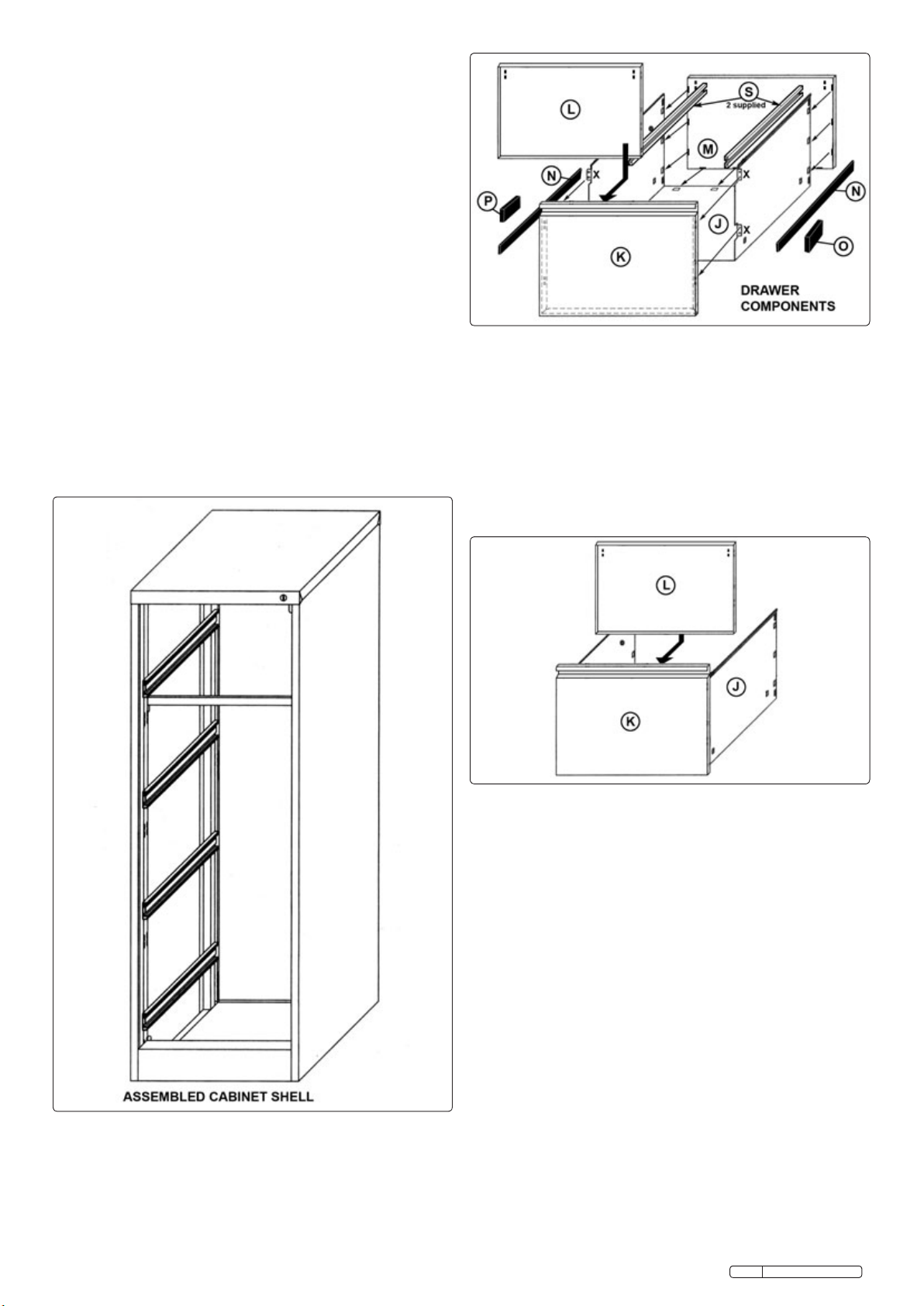
3.8.2 Check that the two tabs (X) on the vertical front edges of the 'U'
shape are bent outwards as shown above. Insert the base and
sides (J) into the open back of the front panel (K) and flex the
vertical sides inwards so that the four tabs go behind the returned
edges at the back of the front panel. Fix the assembly together
with four self tapping screws (Ø9mm) to hold the tabs firmly
behind the back edges of the front panel.
3.8.3 Referring to fig.4 slide the drawer front inner panel (L) down into
the drawer, just behind the front panel (K). Ensure that the
returned edges of the inner panel are facing towards the back of
the front panel. Slide the inner panel (L) into the back of the front
panel (K) so that the tabs on the sides of the inner panel lock into
the slots in the sides of the drawer .
SFC4 Issue No: 1 - 22/02/10
Original Language Version
Fig.2
Fig.3
Fig.4
3.8.4 Now attach the back panel (M) to the drawer. NOTE: If you want
to use the two A4 file runners (S) they should be fitted at the same
time. See fig.5. The rear edges of the 'U' shape have raised hooks
punched into them which line up with slots in the edges of the
back panel (M). Lay the drawer assembly on its front face. If fitting
the file runners (S), push them into the slots at the top of the
drawer inner panel. Then lower the back panel (M) into the 'U'
shape ensuring that the file runners enter the slots in the back
panel and the hooks at the top of the drawer sides also enter the
matching slots in the back panel. The back panel (M) is now tying
together the drawer sides (J) at the top. Gradually ease the rest of
the back panel down into the 'U' shape ensuring that each side
hook engages into the matching slot in the back panel. When all
hooks are engaged push firmly down on to the panel to ensure
that all the hooks are fully inserted into the slots.
3.8.5 At each corner of the assembled back panel is a slot which gives
access to a pair of tabs punched into the 'U' shape. Bend these
tabs into the slots to lock the back panel onto the draw. See fig.6.
3.8.6 The drawer runners (N) attach to the sides of the drawers in a
similar manner to the cabinet runners. Sort the 8 runners into 4 left
hand ones and four right hand ones. Each runner has two hooks
on the rear face which slot into holes in the sides of each draw.
The horizontal hook at the back end of each runner slides
horizontally into the hole at the back of the drawer sides. Once
fully inserted, the hook at the other end of the runner will drop into
the hole at the front of the panel. Pull firmly upwards on the front
end of the runner to engage the hook and the locking tab.
3.8.7 Attach a safety block (P) to the left hand side of each drawer in
the orientation shown in fig.5 using two self tapping screws (Ø9mm).
There are two moulded pins on the back of the moulding which
align with pre-drilled holes in the side of each drawer.
3.8 ASSEMBLE THE DRAWERS.
3.8.1 The bottom and sides of each drawer (see J in fig.3) are supplied
as a flat piece of metal with punched slots creating 'fold' lines'
between the base and sides of the drawer. Place the panel on a
flat surface ensuring that the four tabs (X) on the front edge of the
panel are facing downwards. Place something flat in the centre
portion of the panel and get a second person to firmly hold it in
place. Then bend each side upwards until it is at 90º to the base.
Check the angle with a set square.
3.8.8 Attach a locking block (O) to the right hand side of each drawer in
the orientation shown in fig.5 using two self tapping screws (Ø9mm).
There are two moulded pins on the back of the moulding which
align with pre-drilled holes in the side of each drawer.
3.9 INSERT DRAWERS INTO THE CABINET.
3.9.1 Insert the drawers into the cabinet as follows. Where a drawer is
to be inserted pull the cabinet runners fully out.
3.9.2 Get a second person to help you. Support the drawer at either
side and hold it so that the drawer runners are within the cabinet
runners. Slide each silver ball bearing carrier out to the end of
each cabinet runner until it connects with the drawer runner by at
least 50mm on each side.
3.9.3 Slide the drawer fully into the cabinet. If the drawer is lop sided
and the front is miss-aligned with the cabinet then one or both of
the runners are not sliding within the ball bearing carrier. If the
drawer front fits properly into the cabinet, slide it out again to
check that it has locked in place. It will automatically stop at the
maximum permitted extension.
3.9.4 To remove a drawer, slide the draw out fully until it stops. Where
the drawer runner protrudes from the cabinet runner a small
black lever can be seen within the runner. See inset fig.8. Push
the left hand lever down and hold it down. Pull the right hand
lever up and keep it there. When the drawer is pulled further out
the drawer runners will release from the cabinet runners and the
drawer can be removed.
3.10 CABINET OPERATION.
3.10.1 To lock the cabinet, insert the key and turn it fully clockwise. Test
each drawer to ensure it is locked. To open the cabinet, turn the
key fully anti-clockwise.
3.10.2 When the cabinet is unlocked the safety mechanism ensures
that only one drawer can be opened at a time to prevent the
cabinet from toppling when fully loaded. Test the mechanism by
opening one drawer. Whilst the drawer is open it should not be
possible to open other drawers. If another drawer opens check
that the safety block (P) is installed and correctly fixed.
3.10.3 Move the cabinet to its final location before filling it with files.
SFC4 Issue No: 1 - 22/02/10
Original Language Version
Fig.5
Fig.6
Fig.7
Fig.8
NOTE: It is our policy to continually improve products and as such we reserve the right to alter data, specifications and component parts without prior notice.
IMPORTANT: No liability is accepted for incorrect use of this product.
WARRANTY: Guarantee is 12 months from purchase date, proof of which will be required for any claim.
INFORMATION: For a copy of our latest catalogue and promotions call us on 01284 757525 and leave your full name and address, including postcode.
01284 757500
01284 703534
sales@sealey.co.uk
Sole UK Distributor, Sealey Group,
Kempson Way, Suffolk Business Park,
Bury St. Edmunds, Suffolk,
IP32 7AR
www.sealey.co.uk
Web
email

Other Sealey Industrial Equipment manuals

Sealey Quality Machinery HPT750.V2 User manual

Sealey

Sealey Quality Machinery HPT750.V2 User manual

Sealey PT1000G.V2 User manual

Sealey

Sealey PT1000G.V2 User manual

Sealey LS501 User manual

Sealey

Sealey LS501 User manual

Sealey RE97XS05 User manual

Sealey

Sealey RE97XS05 User manual

Sealey YK20F.V3 User manual

Sealey

Sealey YK20F.V3 User manual

Sealey YK309FAH User manual

Sealey

Sealey YK309FAH User manual

Sealey PBS91.V4 User manual

Sealey

Sealey PBS91.V4 User manual

Sealey APIC1800F User manual

Sealey

Sealey APIC1800F User manual

Sealey AK459DX.V2 User manual

Sealey

Sealey AK459DX.V2 User manual

Sealey SSG1P/3.V3 User manual

Sealey

Sealey SSG1P/3.V3 User manual

Sealey SM19.V2 User manual

Sealey

Sealey SM19.V2 User manual

Sealey ADT200 User manual

Sealey

Sealey ADT200 User manual

Sealey VS207.V2 User manual

Sealey

Sealey VS207.V2 User manual

Sealey VS2073 User manual

Sealey

Sealey VS2073 User manual

Sealey HCC08 User manual

Sealey

Sealey HCC08 User manual

Sealey BTR4.V2 User manual

Sealey

Sealey BTR4.V2 User manual

Sealey WS681.V2 User manual

Sealey

Sealey WS681.V2 User manual

Sealey hp5 User manual

Sealey

Sealey hp5 User manual

Sealey VS3847 User manual

Sealey

Sealey VS3847 User manual

Sealey SB990 User manual

Sealey

Sealey SB990 User manual

Sealey ADT7 User manual

Sealey

Sealey ADT7 User manual

Sealey PT500.V2 User manual

Sealey

Sealey PT500.V2 User manual

Sealey AK468DXP User manual

Sealey

Sealey AK468DXP User manual

Sealey ADT7.V2 User manual

Sealey

Sealey ADT7.V2 User manual

Popular Industrial Equipment manuals by other brands

KStrong AFA930602 User instruction manual

KStrong

KStrong AFA930602 User instruction manual

Phoenix Contact ST 4-PE installation instructions

Phoenix Contact

Phoenix Contact ST 4-PE installation instructions

MyBinding SealerSales W-2510H instruction manual

MyBinding

MyBinding SealerSales W-2510H instruction manual

PNI SVM-10K user manual

PNI

PNI SVM-10K user manual

Une ZHERO manual

Une

Une ZHERO manual

Desoutter Industrial Tools SD Series Servicing and operating instructions

Desoutter

Desoutter Industrial Tools SD Series Servicing and operating instructions

BST iPQ-Spectral operating manual

BST

BST iPQ-Spectral operating manual

3M Liqui-Cel EXF-10x28 Series Assembly and disassembly instructions

3M

3M Liqui-Cel EXF-10x28 Series Assembly and disassembly instructions

Zilmet CAL PRO Instructions for installation and operation

Zilmet

Zilmet CAL PRO Instructions for installation and operation

Eaton MTL F809F-Plus manual

Eaton

Eaton MTL F809F-Plus manual

ABB HT611140 Operation manual

ABB

ABB HT611140 Operation manual

Eaton ET5040 Update instructions

Eaton

Eaton ET5040 Update instructions

PKP DG04 Series instruction manual

PKP

PKP DG04 Series instruction manual

Spirax Sarco AE50S Installation and maintenance instructions

Spirax Sarco

Spirax Sarco AE50S Installation and maintenance instructions

ABB HT587349 Operation manual

ABB

ABB HT587349 Operation manual

Haas Automation UMC-1000 Operator's manual supplement

Haas Automation

Haas Automation UMC-1000 Operator's manual supplement

MR VACUTAP VR Installation and commissioning instructions

MR

MR VACUTAP VR Installation and commissioning instructions

WCS Dumpsters FEL 4 Assembly instructions

WCS

WCS Dumpsters FEL 4 Assembly instructions

manuals.online logo
manuals.online logoBrands
  • About & Mission
  • Contact us
  • Privacy Policy
  • Terms and Conditions

Copyright 2025 Manuals.Online. All Rights Reserved.