Handle Retaining Bolt
2. INTRODUCTION
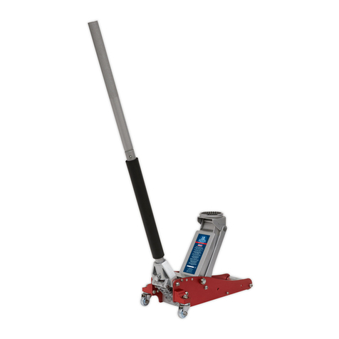
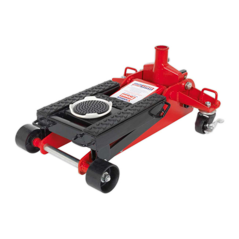
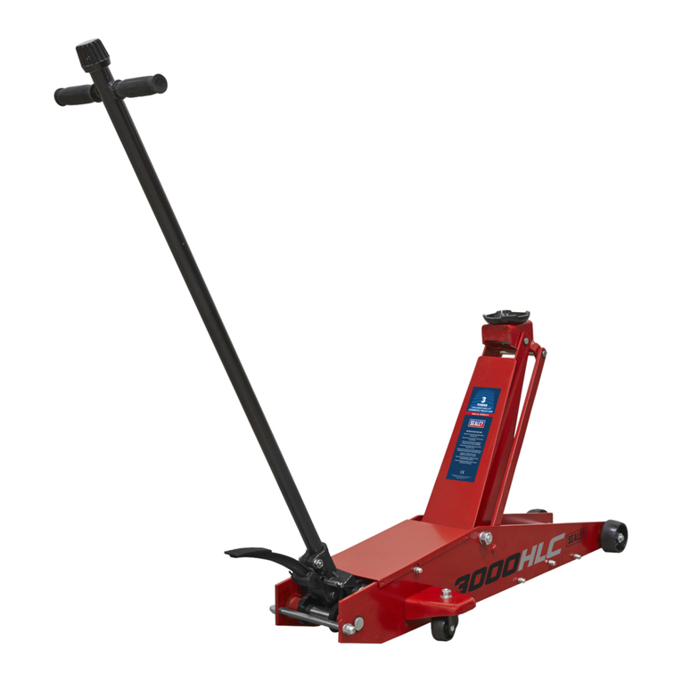
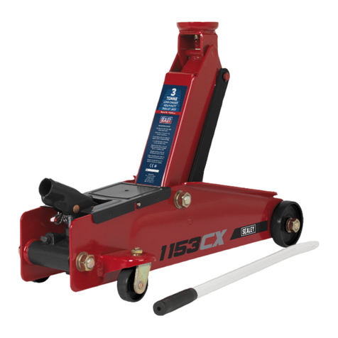
Twin piston Rocket Lift feature brings saddle to maximum height in minimal strokes. Universal joint release mechanism allows safer,
more controlled lowering of jack. Proled lifting arm gives low clearance height of just 85mm making it suitable for sports and custom
cars. Heavy-duty steel chassis provides stability and endurance. Fitted with an overload valve for added safety. Hydraulic oil bypass
system protects ram from being overextended.
3. SPECIFICATION
Model No:.............................3000LE.V2, 3000LEHV.V2
Applicable Standard:.........................................EN 1494
Capacity:............................................................ 3 Tonne
Length:................................................................702mm
Maximum Chassis Height: ..................................153mm
Maximum Saddle Height: ....................................500mm
Minimum Saddle Height: .......................................85mm
Optional Rubber Jack Pad (not supplied)................JP17
4. OPERATION
WARNING! Before use ensure you have read, understood and applied Section 1 safety precautions.
IMPORTANT: Before use, the operator is to visually inspect the jack for cracked welds, damaged or missing parts or hydraulic leaks.
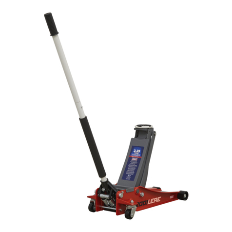
4.1. RELEASING THE RETAINING CLIP (FIG.1)
4.1.1. Seek assistance from a second person if required.
4.1.2. Insert the lower handle section into the handle socket to aid in releasing pressure in the handle socket.
4.1.3. Ensure the handle is secure and fully engaged with the release valve.
4.1.4. Push down on the handle and hold down while unscrewing the handle retaining bolt that is securing the handle socket in the
down position.
4.1.5. Remove the clip from the bolt and the lower chassis bar.
4.1.6. Gently and in a controlled manner slowly allow the lower handle section and handle socket to raise to their upright position.
4.1.7. Replace the handle retaining bolt to secure the handle in the socket.
4.2. BEFORE USE
4.2.1. Insert the upper handle into the lower handle.
4.2.2. Check the lower handle is secure and fully engaged with the release valve.
4.2.3. Tighten the handle retaining bolt.
4.3. HYDRAULIC SYSTEM PURGING
4.3.1. Open the release valve by turning it one full turn counter-clockwise.
4.3.2. Pump the handle 20 times.
4.3.3. Close the release valve by turning it clockwise.
4.4. RAISING A VEHICLE
We recommend that efforts of raising the load shall be reduced by the use of assistance during this operation.
4.4.1. Ensure that the jack and the vehicle are on a hard, level surface.
4.4.2. Ensure that the vehicle handbrake is engaged and that the vehicle wheels are chocked.
4.4.3. Consult the vehicle manual to determine the location of jacking points.
4.4.4. Position the jack under a suitable lifting point.
4.4.5. Turn the slow release valve clockwise, to the closed position. DO NOT over-tighten.
4.4.6. Raise the vehicle to the desired height by pumping the handle up and down.
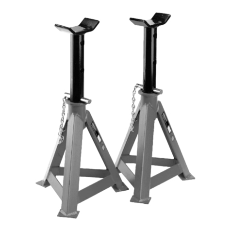
4.4.7. Place axle stands beneath the locations recommended by the vehicle manufacturer.
4.4.8. Turn the release valve slowly counter-clockwise to lower the vehicle on to the axle stands.
4.5. LOWERING A VEHICLE
4.5.1. Turn the release valve clockwise to the closed position.
4.5.2. Pump the handle to raise the vehicle o the axle stands.
4.5.3. Remove the axle stands from beneath the vehicle.
4.5.4. Turn the release valve counter-clockwise to lower the vehicle to the ground.
NOTE: This jack is fitted with a slow release mechanism for controlled descent. When not in use, leave the saddle and ram fully retracted.
5. MAINTENANCE
IMPORTANT: Only fully qualied personnel should attempt maintenance or repair.
Jacks shall be maintained and repaired in accordance with the manufacturer’s instructions. Such maintenance and repair shall be
carried out by qualied persons. No modications shall be carried out which adversely aect the compliance of the jack with the
standard. Check the state of the markings and that the markings remain as the initial one.
5.1. When not in use, the ram should be in its lowest position to minimise corrosion. Remove the handle to deactivate jack.
5.2. Keep the jack clean and lubricate all moving parts with oil on a regular basis.
5.3. To check the oil level, fully lower the jack. Remove ller plug (g.3). The correct oil level should be approximately 5mm below the ller
opening. If oil level is low, ll as required. Pump unloaded jack 15 to 20 times to expel air and then ret plug.
NOTE: Use a good quality jack oil, such as SEALEY HYDRAULIC JACK OIL.
Original Language Version
© Jack Sealey Limited 3000LE.V2, 3000LEHV.V2 Issue 3 (1,4) 06/09/23
FIG.1 FIG.2 FIG.3
