Sealey JKIT01 User manual

INSTRUCTIONS FOR
LIFTING KIT 2TONNE 5PC
MODEL NO: JKIT01
Thank you for purchasing a Sealey product. Manufactured to a high standard, this product will, if used according to these instructions,
and properly maintained, give you years of trouble free performance.
IMPORTANT: PLEASE READ THESE INSTRUCTIONS CAREFULLY. NOTE THE SAFE OPERATIONAL REQUIREMENTS, WARNINGS & CAUTIONS. USE
THE PRODUCT CORRECTLY AND WITH CARE FOR THE PURPOSE FOR WHICH IT IS INTENDED. FAILURE TO DO SO MAY CAUSE DAMAGE AND/OR
PERSONAL INJURY AND WILL INVALIDATE THE WARRANTY. KEEP THESE INSTRUCTIONS SAFE FOR FUTURE USE.
1. SAFETY
TROLLEY JACK
9Ensure the jack is in sound condition and good working order. Take action for immediate repair or replacement of damaged parts.
Use genuine parts only. The use of improper parts may be dangerous and will invalidate the warranty.
9Locate the jack in a suitable, well lit working area.
9Keep working area clean and tidy and free from unrelated materials.
9Use jack on level and solid ground, preferably concrete. Avoid tarmacadam as jack may sink in.
9Place chocks under wheels of vehicle (but ensure wheels of jack can freely move).
9Ensure the vehicle handbrake is engaged, engine is switched off and transmission is in gear (or “PARK” if automatic).
9Ensure minimum distance of 0.5m between vehicle and static objects such as doors, walls, etc., to allow for vehicle tilting.
9Ensure there are no passengers in the vehicle.
9Ensure all non-essential persons keep a safe distance whilst the jack is in use.
9Only place jack under those lifting points recommended by vehicle manufacturer (see vehicle handbook).
9Check the lifting point is stable and centred on the jack saddle.
9Ensure the jack wheels are free to move and that there are no obstructions.
▲DANGER! Use the jack for lifting only, NOT for supporting the lifted load.
9Use suitable capacity axle stands under the vehicle before proceeding with any task.
9Ensure there are no persons or obstructions beneath the vehicle before lowering.
9Use a qualified person to maintain or repair the jack hydraulic system.
8DO NOT operate the jack if damaged.
8DO NOT allow untrained persons to operate the jack.
8DO NOT exceed the rated capacity of the jack (2 tonne). When lifting a load of maximum capacity or close to it, it is recommended that
the effort be reduced by the use of assistance during this operation.
8DO NOT allow the vehicle to move while supported by the jack, or use the jack to move the vehicle.
8DO NOT jack vehicle if there is a risk of spillage of fuel, battery acid, or other dangerous substances.
8DO NOT work under the vehicle until axle stands have been correctly positioned.
8DO NOT use the jack for purposes other than that for which it is intended.
8DO NOT top up hydraulic system with brake fluid. Use hydraulic jack oil only.
8DO NOT adjust the safety overload valve.
9When not in use store jack, fully lowered, in a safe, dry, childproof area.
AXLE STANDS
WARNING!
DO NOT OVERLOAD AXLE STANDS BEYOND RATED CAPACITY. OVERLOADING CAN CAUSE DAMAGE TO, OR FAILURE OF,
THE AXLE STANDS. POSITION LOAD ON CENTRE OF CRUTCH/SADDLE ONLY. ALWAYS USE STANDS IN PAIRS ON HARD
LEVEL SURFACE CAPABLE OF SUSTAINING THE LOAD. USE OF STANDS ON OTHER THAN HARD LEVEL SURFACES CAN
RESULT IN LOAD INSTABILITY AND POSSIBLE LOSS OF LOAD. DO NOT USE ON TARMACADAM. FAILURE TO FOLLOW
THESE INSTRUCTIONS MAY RESULT IN DAMAGE TO AXLE STANDS, LOSS OF LOAD RESULTING IN PROPERTY DAMAGE,
SERIOUS PERSONAL INJURY OR LOSS OF LIFE.
▲DANGER! GREAT CARE MUST BE TAKEN TO ENSURE YOU LOWER THE VEHICLE (OR OTHER LOAD)
SLOWLY AND CAREFULLY ONTO THE CENTRES OF THE CRUTCH/SADDLE OF THE AXLE STANDS.
9Use only as specified by the manufacturer.
9Ensure the load does not exceed the maximum capacity as marked on the axle stand, per pair.
9Use no more than a single pair of stands either on the front, rear or one side of the vehicle. Use in pairs.
9No alterations or modifications shall be made to this product.
9Use on a hard, level surface, e.g. concrete. DO NOT use on uneven ground or tarmacadam.
9Securely chock wheels in contact with the ground. Before jacking and placing the stands, apply vehicle
handbrake (put automatics in ‘Park’).
9Make sure that each stand is securely located under a strong point on the vehicle; consult the vehicle manufacturer’s handbook for
guidance. Ensure that height adjust locking mechanism is fully located before applying any load to the axle stand.
9Ensure that the load is located centrally on the saddle, and that the weight is directed through the vertical axis of the stand.
9Exercise extra care when using with a three wheeled vehicle or a trailer. Refer to vehicle manufacturer’s instructions.
JKIT01| Issue 4 27/09/16
Original Language Version
© Jack Sealey Limited
Refer to
Instructions

9Once vehicle is supported, ensure that the vehicle and stands are stable before starting work. Ensure that it is not possible for the vehicle
to move before commencing any work.
9Inspect stands before each use. DO NOT use if they show signs of damage. DO NOT use if it is suspected that they have been
overloaded.
9Before commencing any work or going beneath the vehicle, undertake a risk assessment. Ensure that a responsible person is aware of
the work about to be undertaken.
9Replace any labels on the axle stand should they become unreadable. This applies in particular to any warning or operation instruction
labels. If replacement labels are required, contact your Sealey stockist.
8DO NOT use axle stands on the highway, or anywhere else if it is deemed to be unsafe.
8DO NOT push or twist the vehicle/load whilst it is supported on stands.
8DO NOT mix components between stands. Use only as supplied.
8DO NOT allow children or animals in the vicinity of a vehicle supported on axle stands.
8DO NOT leave a vehicle on axle stands in an area that could be considered a hazard to others or property.
9FOLLOW STEPS 1, 2, AND 3 TO CORRECTLY PLACE VEHICLE / LOAD ONTO AXLE STANDS.
2. IINTRODUCTION
Comprises essential equipment required to safely jack up a vehicle. Includes a 2tonne trolley jack, a pair of folding wheel chocks, a pair of axle
stands (2tonne combined), 6 wheel padded creeper for comfort whilst carrying out maintenance and an extending L-bar wrench with 17mm & 19mm
socket.
3. ISPECIFICATION
Model no: .................................................................. JKIT01
Jack:
Capacity:................................................. 2 tonnes (2,000 kg)
Minimum saddle height: ............................................. 140mm
Maximum saddle height: ............................................ 340mm
Maximum chassis height:........................................... 123mm
Length:....................................................................... 450mm
Weight:.......................................................................... 8.7kg
Axle stands:
Capacity each: .......................................... 1 tonne (1,000 kg)
Capacity pair: .......................................... 2 tonnes (2,000 kg)
Minimum height:......................................................... 291mm
Maximum height:........................................................ 391mm
Creeper:
Frame:............................................................................ steel
Size L x W x D:........................................901 x 425 x 120mm
Wheels:................................................................................6
JKIT01| Issue 4 27/09/16
Original Language Version
© Jack Sealey Limited

4. BEFORE FIRST USE
TROLLEY JACK
Before using jack, purge hydraulic unit in order to eliminate any air in the system. Locate the handle (fig.1H) onto the release valve nut (fig.1B) and
open valve by turning the handle anti-clockwise, place handle back into the jacking point (fig.1A) and pump for 30 to 40 seconds. When complete,
close the release valve by turning the valve nut (fig.1B) clockwise.
Place a few drops of hydraulic jack oil on pump piston. Thoroughly lubricate moving parts.
AXLE STANDS See fig.2
Familiarise yourself with the product. Check that the stands are in good order and condition. Insert the centre column in the centre tube, adjust to
height required and insert the locking pin and secure with R pin. When lowering the centre column, hold the centre column firmly before removing
the pin. Failure to do so will allow the centre column to free fall through the centre tube which may be dangerous.
5. OPERATION
5.1. TROLLEY JACK
5.1.1. General.
WARNING! Before lifting ensure Section 1 safety instructions are read and understood.
5.1.1.1. Prepare the vehicle as mentioned in the safety instructions ensuring the ground on which the jack is to stand is level and solid (not
tarmacadam).
5.1.1.2. Position the jack saddle under the vehicle manufacturer’s recommended lifting point.
5.1.2. Jacking the vehicle.
5.1.2.1. Turn the handle clockwise to close the release valve (fig.1B) place handle in jacking point (fig.1A) and commence pumping handle up
and down, using maximum strokes, until the jack saddle reaches the vehicle jacking point. Check the jacking point is centrally located on
the saddle and raise the vehicle.
5.1.2.2.
Should the jack become overloaded, a safety excess pressure valve will open, and stop the vehicle from lifting.
WARNING! The jack is a lifting device only and must not be used to support the load. Use correctly rated axle stands to support the load.
5.1.2.3. When lifting a load of maximum capacity (2 tonnes) or close to it, it is recommended that the effort be reduced by the use of assistance
during this operation.
5.1.3. Lowering the vehicle
5.1.3.1. If using axle stands, raise the jack high enough for the stands to be easily removed. Then place handle on release valve nut (fig.1B)
and turn anti-clockwise, very slowly, to open the valve.
5.1.3.2. The lowering speed is controlled by the amount you turn the handle. Lower carefully, avoid any sudden changes in descent rate
which would shock load the hydraulic system.
WARNING! Ensure there are no persons or obstacles beneath the vehicle, or in the path of its descent.
5.2. AXLE STANDS
5.2.1. Ensure the maximum load does not exceed 2 tonnes per pair of axle stands (1 tonne for each stand).
5.2.2. Refer to vehicle owner’s handbook for correct jacking procedure. Check to ensure that manufacturer’s recommended jacking points are in
good condition.
5.2.3. Ensure the vehicle parking brake is on and wheels are chocked.
5.2.4. Adjust height of stand to correspond with the raised vehicle.
5.2.5. Check that the locking pin is correctly pushed all the way through the centre column and out of the other side, with the R clip inserted.
Position stands under vehicle at points specified by vehicle manufacturer.
5.2.6. Carefully and slowly lower the load onto stands. Ensure the jacking points sit in the centre of the stand saddles and check that the stands
are stable and not leaning. Also ensure that there are no objects or persons that could impede the safe lowering of the vehicle onto the
stands.
5.2.7. After use, hold the centre column (fig.2) firmly when removing the locking pin (fig.2). Failure to do so will allow the centre column to
fall freely through the main centre tube which could be dangerous.
WARNING! Ensure you follow all instructions carefully. DO NOT load stands off centre. Failure to heed this warning may cause damage,
serious injury or loss of life!
5.3. WHEEL CHOCKS
5.3.1.
Ensure the vehicle handbrake is engaged, engine is switched off and transmission is in gear (or “PARK” if automatic).
5.3.2.
Always use chocks in pairs, one pair per tyre.
5.3.3. Unfold the chock and pull up the support bar until it stops. Lock the support bar into its groove.
5.3.4. Place one chock in front and one behind the tyre, centred on the tread of the tyre.
WARNING! Chocks are designed to be used on hard, level surfaces, capable of sustaining the load.
JKIT01| Issue 4 27/09/16
Original Language Version
© Jack Sealey Limited
H
A
BO
fig 2
fig 1

JKIT01| Issue 4 27/09/16
Original Language Version
© Jack Sealey Limited
5.4. CREEPER
5.4.1.
Push the two halves of the creeper together and secure with the pins, one each side.
6. MAINTENANCE
6.1. TROLLEY JACK
6.1.1. When the jack is not in use, the ram should be in its lowest position to minimise corrosion. Remove the handle to inactivate jack.
6.1.2. Keep the jack clean and lubricate all moving parts with acid free oil on a regular basis.
6.1.3. Before each use check for broken, cracked, bent, or loose parts, or any visible damage to ram, pump, saddle, lifting arm, frame and
all parts including nuts, bolts, pins and other fasteners. If any suspect item is found remove jack from service and take necessary
action to remedy the problem.
6.1.4. DO NOT use the jack if believed to have been subjected to abnormal load or shock load.
6.1.5. Periodically check the pump piston and the ram for signs of corrosion. Clean exposed areas with a clean oiled cloth.
6.1.6. After one year the oil should be replaced in order to extend the life of the jack. Use hydraulic jack oil only.
6.1.7. IMPORTANT: Only fully qualified personnel should attempt hydraulic maintenance or repair.
6.1.8. To check the oil level, fully lower the jack. Remove filler screw (fig.1.O). The correct level is the bottom of the screw hole. If oil level
is low, fill as required.
NOTE: Use a good quality jack oil, such as SEALEY HYDRAULIC JACK OIL.
WARNING: DO NOT use brake fluid, or any fluid other than hydraulic jack oil as this may cause serious damage to the jack and will
invalidate the warranty!
6.1.9. To drain the oil, remove the filler plug and raise front of jack. Make sure that no dirt is allowed to enter the hydraulic system.
IMPORTANT: NO RESPONSIBILITY IS ACCEPTED FOR INCORRECT USE OF THIS PRODUCT.
6.1.10. Owing to their size and weight, hydraulic products should ideally be repaired by local service agents. We have service/repair agents
in most parts of the UK. Before returning your product please telephone our technical help line on 01284 7575505 for advice
and trouble shooting guidance.
6.1.11. De-commissioning the Jack - Should the jack become completely unserviceable and require disposal, draw off the oil into an
approved container and dispose of the jack and the oil according to local regulations.
6.2. AXLE STANDS
6.2.1. Before each use check to ensure stands and stand welds are not cracked, and that there are no missing and/or damaged parts.
WARNING! Any stand that appears to be damaged in any way must be removed from service immediately.
6.2.2. Ensure the locking pin and R clip are in good order and condition.
6.2.3. Due to the potential hazards associated with these stands, do not misuse, or make any modification to the stands or components.
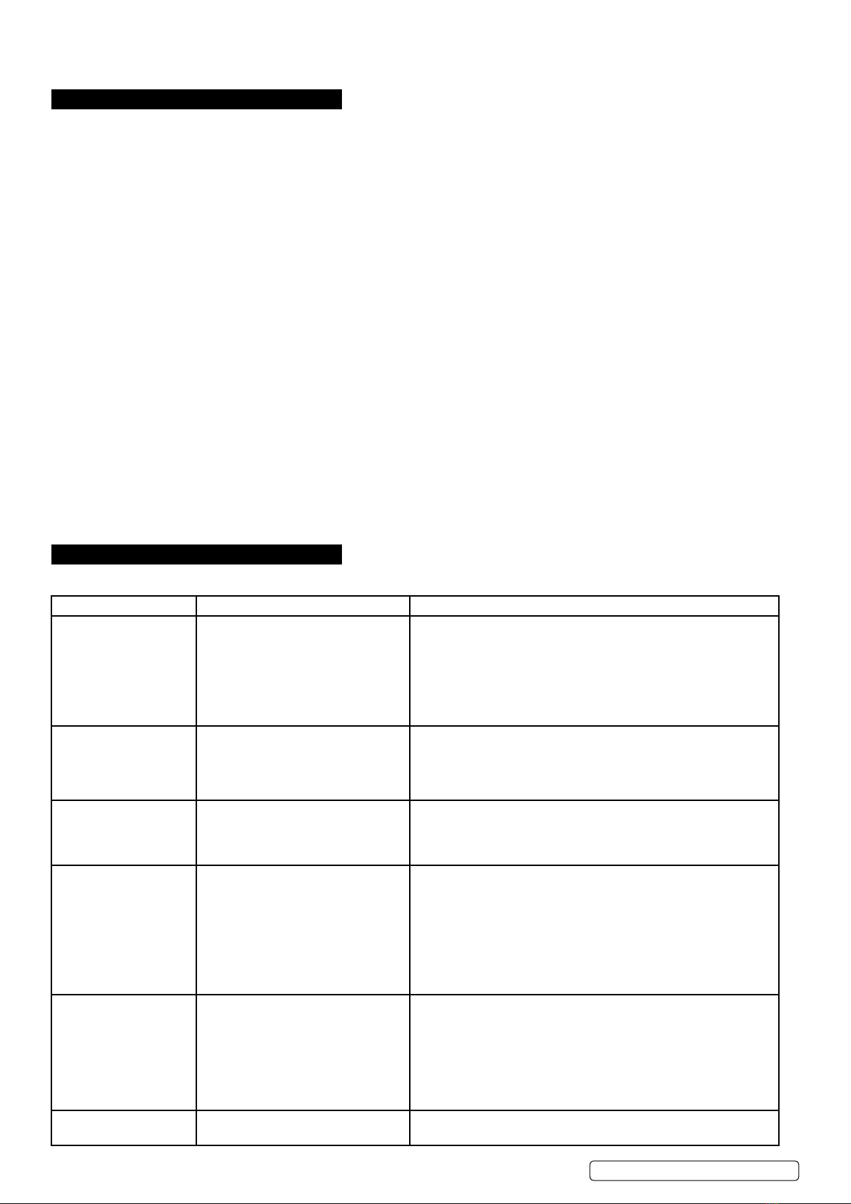
7. TROUBLESHOOTINGt
IMPORTANT: MAINTENANCE OR REPAIR OF THE HYDRAULIC SYSTEM MUST ONLY BE PERFORMED BY A QUALIFIED PERSON.
Problem Possible Cause Remedy
Jack will not lift the load 1) Overloaded.
2) Oil level low.
3) Release valve not correctly
closed.
4) Air in system.
5) Piston rod not functioning.
6) Packing worn or defective.
1) Use a jack with adequate capacity.
2) Top up oil.
3) Check and close release valve.
4) Open release valve and pump the handle a few times.
5) Clean and replace oil.
6) Replace packing.
Jack does not lift high
enough or fells ‘spongy’.
1) Oil level too high or too low
2) Worn seals
3) Air in system
4) Release valve not closed
1) Fill or remove excess oil
2) Return jack to local service agent
3) Open release valve and pump the handle a few times. Close
valve and re-try
4) Check and close release valve
Jack lifts poorly. 1) Pump packing or valves
malfunctioning
2) Oil is dirty
3) Air in the system
1) Replace packing and/or clean valves
2) Replace oil
3) Open release valve and pump the handle a few times. Close
valve and re-try
Jack lifts but will not hold
the load.
1) Release valve partially open
2) Dirt on valve seats
3) Air in system
4) Faulty seals
1) Check and close release valve
2) Lower jack, close release valve. Place foot on front wheel
and pull up lifting
arm to its full height by hand.
Open the release valve to lower arm
3) Open release valve and pump the handle a few times. Close
valve and re-try
4) Replace packing or contact local service agent
Jack will not lower
completely
1) Unit requires lubrication
2) Piston rod bent or damaged
3) Jack frame/link system distorted
due to overloading/poor positioning
4) Air in system
5) Release valve partially closed
6) Jack spring damaged or unhooked
1) Oil all external moving parts
2) Replace rod or contact local service agent
3) Replace damaged parts or contact local service agent
4) Open release valve and pump the handle a few times. Close
valve and re-try
5) Check and fully open release valve
6) Replace spring or contact local service agent
Jack does not lower at
all.
1) Release valve closed. 1) Check and fully open release valve.

NOTE: It is our policy to continually improve products and as such we reserve the right to alter data, specications and component parts without prior notice.
IMPORTANT: No liability is accepted for incorrect use of this product.
WARRANTY: Guarantee is 12 months from purchase date, proof of which will be required for any claim.
Sole UK Distributor, Sealey Group.
Kempson Way, Suffolk Business Park,
Bury St. Edmunds, Suffolk.
IP32 7AR
www.sealey.co.uk
sales@sealey.co.uk
01284 757500
01284 703534
Web
Environmental Protection
Recycle unwanted materials instead of disposing of them as waste. All tools, accessories and packaging should be
sorted, taken to a recycling centre and disposed of in a manner which is compatible with the environment.
When the product becomes completely unserviceable and requires disposal, drain off any fluids (if applicable)
into approved containers and dispose of the product and the fluids according to local regulations.
Parts support is available for this product. To obtain a parts listing and/or diagram,
please log on to www.sealey.co.uk, email sales@sealey.co.uk or telephone 01284 757500.
JKIT01| Issue 4 27/09/16
Original Language Version
© Jack Sealey Limited
Table of contents
Other Sealey Jack manuals

Sealey
Sealey 3000CXD.V3 User manual

Sealey
Sealey TJ150E User manual

Sealey
Sealey 300ETJ.V2 User manual

Sealey
Sealey RJA1800.V4 User manual

Sealey
Sealey National Machinery NA3010 User manual

Sealey
Sealey RJAS1500 User manual

Sealey
Sealey 1153CXHV User manual

Sealey
Sealey 800GTA User manual

Sealey
Sealey RJA1550 User manual

Sealey
Sealey 1020LEO User manual

Sealey
Sealey 3290CX User manual

Sealey
Sealey 1250GTA User manual

Sealey
Sealey FJ48 User manual

Sealey
Sealey 3000LE Series User manual

Sealey
Sealey 3001LE User manual

Sealey
Sealey 7001.V2 User manual

Sealey
Sealey 1000TR User manual

Sealey
Sealey Quality machinery PREMIER TJ3.V3 User manual

Sealey
Sealey 1100CXD.V5 User manual

Sealey
Sealey 2200HL.V4 User manual