manuals.online logo
Brands
  1. Home
  2. •
  3. Brands
  4. •
  5. Sealey
  6. •
  7. Lifting System
  8. •
  9. Sealey MT680.V3 User manual

Sealey MT680.V3 User manual

Thank you for purchasing a Sealey product. Manufactured to a high standard this product will, if used according to these instructions and
properly maintained, give you years of trouble free performance.
1. SAFETY INSTRUCTIONS
3.1 Content
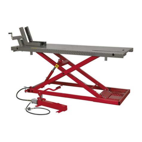
3.1.1 The Vehicle Lift comprises:
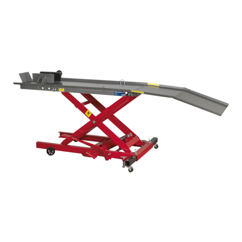
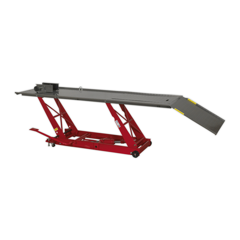
Main lift assembly. Leading plate. Manual hydraulic pump assembly. Side extensions. Ramp extensions. Connecting bar. Motorcycle
Wheel Clamp. Bolts, nuts and washers.
3.2 Assembly (Refer to Fig 3.)
3.2.1 Attach the sliding plate (8) to the platform using bolts, washers and nuts.
3.2.2 Connect the oil hose coupler (30) to the port on the hydraulic pump.
3.2.3 Attach the leading plate (9) to the end of the platform.
3.2.4 If necessary, when lifting vehicles, attach the two side extensions (51A) and (51) to the platform using the panel pipes (52) the
pins (49), washers (50) and nuts (54).
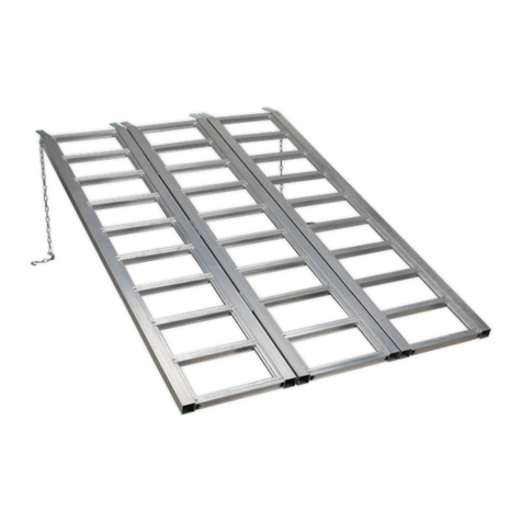
3.2.5 Attach the ramp extensions (53) and (53A) to the side extensions.
3.3 Motorcycle Wheel Clamp
3.3.1 Remove the clamp from the box and take the handle section (Fig.2A) and bolt to the top of the lift, through the pre-drilled holes, using
large bolts, nuts and washers.
3.3.2 Next take the moving jaw (Fig.2B) and bolt it to the handle section with the small bolts supplied.
3.3.3 Finally take the fixed jaw (Fig.2C) and bolt it to the top of the lift, through the remaining holes, using large bolts, nuts and washers.
2. INTRODUCTION AND SPECIFICATION
IMPORTANT: PLEASE READ THESE INSTRUCTIONS CAREFULLY. NOTE THE SAFE OPERATIONAL REQUIREMENTS, WARNINGS & CAUTIONS.
USE THE PRODUCT CORRECTLY AND WITH CARE FOR THE PURPOSE FOR WHICH IT IS INTENDED. FAILURE TO DO SO MAY CAUSE
DAMAGE AND/OR PERSONAL INJURY AND WILL INVALIDATE THE WARRANTY. PLEASE KEEP INSTRUCTIONS SAFE FOR FUTURE USE.
2.1 Introduction
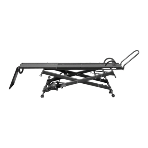
All-steel construction with heavy-duty hydraulic ram. Supplied with
separate, foot operated, hydraulic pump and reservoir unit.
Features two additional side platforms for extra width. Ramp and
platform made with chequer plate surface to ease loading and
positioning of mini tractor/quad. Supplied with motorcycle front
wheel locking attachment, securing vehicle to provide easy
maintenance access. Fitted with safety lock to prevent accidental
lowering. Suitable for use with centre stand motorcycles or with
paddock stand.
2.2 Specification
Model . . . . . . . . . . . . . . . . . . . . . . . . . . . . . . . . . . . . . MT680.V3
Capacity . . . . . . . . . . . . . . . . . . . . . . . . . . . . . . . . . . . . . . .680kg
Minimum Height . . . . . . . . . . . . . . . . . . . . . . . . . . . . . . . .190mm
Maximum Height . . . . . . . . . . . . . . . . . . . . . . . . . . . . . . ..790mm
Standard Width . . . . . . . . . . . . . . . . . . . . . . . . . . . . . . . . 710mm
Maximum Width . . . . . . . . . . . . . . . . . . . . . . . . . . . . . . .1220mm
Length . . . . . . . . . . . . . . . . . . . . . . . . . . . . . . . . . . . . . .2000mm
Table Size . . . . . . . . . . . . . . . . . . . . . . . . . . . . . . 710 x 2000mm
Side Extension . . . . . . . . . . . . . . . . . . . . . . . . . . 254 x 2000mm
 WARNING! Ensure Health & Safety, local authority and general workshop practice regulations are adhered to when using this equipment.
Use a qualified person to lubricate and maintain the lift. DO NOT use brake fluid to top up hydraulic unit. Use Sealey hydraulic oil only.
Replace or repair damaged parts. Use genuine parts only. Unauthorised parts may be dangerous and will invalidate the warranty.
Keep the lift clean for best and safest performance.
Locate the lift in a suitable work area. Keep area clean and tidy and free from unrelated materials, and ensure that there is adequate lighting.
 WARNING! Use lift on level and solid ground, preferably concrete. Avoid tarmacadam since the lift may sink into the surface.
 Maintain correct balance and footing. Ensure that the floor is not slippery and wear non-slip shoes.
Keep children and non-essential persons away from the work area.
 Never operate the lift with a load heavier than 680kg. Ensure the load is evenly distributed on the platform and secured if necessary.
 Before lifting check that there are no overhead obstructions.
 When raised, insert the safety bar to keep the platform from lowering.
 When work is complete, check under the platform to ensure that there are no obstructions and that it is safe to lower the unit.
 DO NOT operate the lift if any parts are damaged or missing as this may cause failure and/or possible personal injury.
 DO NOT place any part of your body within or under the lift during use.
 DO NOT operate the lift when you are tired or under the influence of alcohol, drugs or intoxicating medication.
 DO NOT use the lift for any purpose other than that for which it is designed.
 DO NOT allow untrained persons to operate the lift.
 DO NOT make any modifications to the lift.
 DO NOT expose the lift to excessive moisture or allow it to get wet.
 Store lift in a dry, childproof environment when not in use.
Fig.1
Fig.2
3. CONTENT & ASSEMBLY
Original Language Version MT680.V3 Issue: 1 - 01/07/13
A
BC
© Jack Sealey Limited
INSTRUCTIONS FOR:
HYDRAULIC MINI TRACTOR/QUAD
MOTORCYCLE LIFT 680KG CAPACITY
MODEL No: MT680.V3
4. OPERATING INSTRUCTIONS
4.1 Prior To Use
NOTE! MT680 has a vent valve Fig.3A, this is closed for transit only; before use the valve must be lifted or the pump will not
function properly.
4.1.1 Let the hydraulic pump stand for one hour, to allow the oil to settle, before purging the system.
NOTE: Failure to allow sufficient time for the oil to settle could result in air remaining in the oil. Should the pump fail to purge completely
at the first attempt, a second purge will be required.
4.1.2 Purge the hydraulic system by depressing the release foot pedal (34) and pumping the lift foot pedal (32) fifteen to twenty times.
4.1.3 Test the lift unladen by moving the safety handle (47) to the right and raising the lift to full height.
4.1.4 Move the safety handle to the left (in the depression) and lower the lift by depressing the release foot pedal (34) slowly, to control the
rate of descent.
4.2 Operation (Refer to the Parts Diagram)
 WARNING! Ensure that you read, understand and apply the Section 1 Safety Instructions.
 WARNING! DO NOT overload the Vehicle lift. The maximum load is 680kg.
4.2.1 Position the lift in a suitable location, preferably on a concrete surface.
4.2.2 Turn the locking plate base (27) down to ensure that lift is level and stable on the surface.
4.2.3 Wheel the vehicle up the leading plate and on to the lift platform.
 WARNING! The vehicle must be fully supported by the lift platform prior to lifting. DO NOT put the rear wheel of the vehicle
on the leading plate (9) and DO NOT use the leading plate to support the weight of the vehicle when lifting. The leading plate (9)
is only used to assist the operator in wheeling the vehicle on the platform when the lift is at its lowest position.
4.2.4 Secure the vehicle securely to the lift platform. When working on a motorcycle, wheel the bike in to the wheel clamp at the front of the
lift, tighten the clamp to hold the bike in place. Original Language Version MT680.V3 Issue: 1 - 01/07/13
VENT VALVE
LOCATION
Fig.3A
VENT IN TRANSIT
POSITION
OPEN VENT
BEFORE USE
01284 757500
01284 703534 sales@sealey.co.uk
www.sealey.co.uk
Web
email
NOTE: It is our policy to continually improve products and as such we reserve the right to alter data, specifications and component parts without prior notice.
IMPORTANT: No liability is accepted for incorrect use of product.
WARRANTY: Guarantee is 12 months from purchase date, proof of which will be required for any claim.
INFORMATION: For a copy of our latest catalogue and promotions call us on 01284 757525 and leave your full name and address, including postcode.
MODEL:
MINI TRACTOR / QUAD / MOTORCYCLE LIFT
YANKEE 680KG HYDRAULIC
MODEL: MT680.V2
ITEM PART NO DESCRIPTION
1 MT680.01 PLATFORM
2 MT680.V2-02 CRANK HANDLE ASS'Y
3 MT680.V2-03 WHEEL CLAMP
4 MT680.V2-04 BAFFLE PLATE
5 MT680.V2-05 BOLT
6 MT680.V2-06 BOLT
7 MT680.V2-07 M10 FULL HEX NUT BZP
8 MT680.V2-08 SLIDING PLATE
9 MT680.V2-09 LEADING PLATE
10 MT680.V2-10 LOCK PLATE ASS'Y
11 MT680.V2-11 BOLT
12 MT680.V2-12 WASHER
13 MT680.V2-13 BASE ASS'Y
14 MT680.V2-14 STEEL WHEEL
15 MT680.V2-15 LIFTING ARM 1
16 MT680.V2-16 BOLT
17 MT680.V2-17 LIFTING ARM 2
18 MT680.V2-18 BOLT
19 MT680.V2-19 M16 NYLOC NUT S/C
20 MT680.V2-20 M8 SPRING WASHER BZP
21 MT680.V2-21 WASHER
22 MT680.V2-22 M16 SPRING WASHER BZP
23 MT680.V2-23 M16 FULL HEX NUT BZP
24 MT680.V2-24 ADJUSTING SCREW
25 MT680.V2-25 FOOT
26 MT680.V2-26 SAFETY LATCH
27 MT680.V2-27 LOCKING PLATE BASE
ITEM PART NO DESCRIPTION
28 MT680.V2-28 CYLINDER
29 MT680.V2-29 OIL HOSE
30 MT680.V2-30 COUPLER
31 MT680.V2-31 PUMP
32 MT680.V2-32 LIFT FOOT PEDAL
33 MT680.V2-33 FOOT PEDAL PAD
34 MT680.V2-34 RELEASE FOOT PEDAL
35 MT680.V2-35 M6 NYLOC NUT BZP
36 MT680.V2-36 BOLT
37 MT680.V2-37 BOLT
38 MT680.V2-38 WASHER
42 MT680.V2-42 BOLT
43 MT680.V2-43 M8 NYLOC NUT BZP
44 MT680.V2-44 SCREW
45 MT680.V2-45 M10 NYLOC NUT BZP
46 MT680.V2-46 M12 FULL HEX NUT BZP
47 MT680.V2-47 SAFETY HANDLE
48 MT680.V2-48 SAFETY WIRE
49 MT680.V2-49 PIN
50 MT680.V2-50 WASHER
51 MT680.V2-51 SIDE EXTENSION (RIGHT)
51A MT680.V2-51A SIDE EXTENSION (LEFT)
52 MT680.V2-52 EXTENSION PANEL PIPE
53 MT680.V2-53 RAMP EXTENSION (RIGHT)
53A MT680.V2-53A RAMP EXTENSION (LEFT)
54 MT680.V2-54 M12 FULL HEX NUT BZP
Issue: 1
Issue Date: 171110
© Jack Sealey Limited
Fig.3
5. MAINTENANCE
IMPORTANT: Only fully qualified personnel should attempt maintenance or repair on the vehicle lift.
 DO NOT use the lift if it is believed to have been subjected to abnormal shock or load. Inspect the lift and take appropriate action.
5.1 When the lift is not in use, it must be stored in the lowest position in a dry location to minimise ram and piston corrosion.
5.2 Keep the lift clean and wipe off any oil or grease with a clean rag. Lubricate all moving parts.
5.3 Periodically check the ram and piston for signs of corrosion. Clean exposed areas with a clean oil cloth.
5.4 On each occasion before use, check all parts of the lift. If any part is damaged or suspect, remove the lift from service and take the
necessary action to repair the faulty part or parts.
5.5 Purge the hydraulic system to eliminate any air from the system if lift efficiency drops in the course of carrying out the procedures
outlined at Section 4.
5.6 Check the hydraulic oil level. If it is inadequate, remove the rubber plug on the pump and add hydraulic oil as required.
 WARNING! Only a good quality hydraulic oil, such as SEALEY HYDRAULIC JACK OIL, must be used. DO NOT use brake fluid.
IMPORTANT: NO RESPONSIBILITY IS ACCEPTED FOR THE INCORRECT USE OF THE LIFT.
Hydraulic products are only repaired by local service agents. We have service/repair agents in all parts of the UK.
DO NOT RETURN THE LIFTS TO US. Please telephone 01284 757500 to obtain the address and ‘phone number of your local agent. If the
lift is under guarantee, please contact your dealer.
De-commissioning: If - and when - the lift becomes completely unserviceable, draw off the oil into an approved container and dispose of the
lift and the oil according to local regulations.
NOTE: It is our policy to continually improve products and as such we reserve the right to alter data, specifications and component parts without prior notice.
IMPORTANT: No liability is accepted for incorrect use of this product.
WARRANTY: Guarantee is 12 months from purchase date, proof of which will be required for any claim.
INFORMATION: For a copy of our latest catalogue and promotions call us on 01284 757525 and leave your full name and address, including postcode.
01284 757500
01284 703534
sales@sealey.co.uk
Sole UK Distributor, Sealey Group,
Kempson Way, Suffolk Business Park,
Bury St. Edmunds, Suffolk,
IP32 7AR
www.sealey.co.uk
Web
email
Original Language Version MT680.V3 Issue: 1- 01/07/13
NOTE: Before raising the lift, move the safety handle (47) to the right hand side.
4.2.5 When the platform has been raised to the working height, stop pumping the lift foot pedal.
NOTE: Ensure the safety handle is to the right and the lock plate assembly (10) is locked in a corresponding pair of safety latches
(26) to prevent accidental lowering.
4.2.6 When work is completed, remove all tools from underneath the lift before lowering.
4.2.7 Move the safety handle to the left hand side (in the depression) and lower the lift by slowly depressing the release foot pedal (39) to
gently lower the vehicle.
NOTE: Lower the vehicle slowly, in a controlled fashion. Never allow the vehicle to lower rapidly.
4.2.8 When the lift is fully lowered, unsecure the vehicle and remove it from the lift.
© Jack Sealey Limited
Environmental Protection.
Recycle unwanted materials instead of disposing of them as
waste. All tools, accessories and packaging should be sorted,
taken to a recycle centre and disposed of in a manner which
is compatible with the environment.
Parts support is available for this product. To obtain a parts listing and/or a diagram please log on to: www.sealey.co.uk,
email: sales@sealey.co.uk or phone: 01284 757500

Other Sealey Lifting System manuals

Sealey MC455.V2 User manual

Sealey

Sealey MC455.V2 User manual

Sealey PPL01 User manual

Sealey

Sealey PPL01 User manual

Sealey AK98941 User manual

Sealey

Sealey AK98941 User manual

Sealey MT680.V4 User manual

Sealey

Sealey MT680.V4 User manual

Sealey AVR2500A User manual

Sealey

Sealey AVR2500A User manual

Sealey MC365A User manual

Sealey

Sealey MC365A User manual

Sealey DH03.V2 User manual

Sealey

Sealey DH03.V2 User manual

Sealey ES502.V2 User manual

Sealey

Sealey ES502.V2 User manual

Sealey MC480.v2 User manual

Sealey

Sealey MC480.v2 User manual

Sealey MC365A.V2 User manual

Sealey

Sealey MC365A.V2 User manual

Sealey TD1202S User manual

Sealey

Sealey TD1202S User manual

Sealey MC5908 User manual

Sealey

Sealey MC5908 User manual

Sealey MR1.V2 User manual

Sealey

Sealey MR1.V2 User manual

Sealey MC401 User manual

Sealey

Sealey MC401 User manual

Sealey MC390.V2 User manual

Sealey

Sealey MC390.V2 User manual

Sealey FCR500 User manual

Sealey

Sealey FCR500 User manual

Sealey MC365 User manual

Sealey

Sealey MC365 User manual

Sealey DH02 User manual

Sealey

Sealey DH02 User manual

Sealey MC455 User manual

Sealey

Sealey MC455 User manual

Sealey EVBT1000 User manual

Sealey

Sealey EVBT1000 User manual

Sealey DH03.V2 User manual

Sealey

Sealey DH03.V2 User manual

Sealey FCR500 User manual

Sealey

Sealey FCR500 User manual

Sealey MC500 User manual

Sealey

Sealey MC500 User manual

Sealey MC135 User manual

Sealey

Sealey MC135 User manual

Popular Lifting System manuals by other brands

POWERTEX PLM Instructions for use

POWERTEX

POWERTEX PLM Instructions for use

Upright SL20 Series Service & parts manual

Upright

Upright SL20 Series Service & parts manual

RUD VRBS-FIX instructions

RUD

RUD VRBS-FIX instructions

Pro-Lift T-3101 Operating instructions & parts manual

Pro-Lift

Pro-Lift T-3101 Operating instructions & parts manual

Maximum 009-1627-6 instruction manual

Maximum

Maximum 009-1627-6 instruction manual

Ravaglioli RAV222N manual

Ravaglioli

Ravaglioli RAV222N manual

WERTHER INTERNATIONAL 204I/B 3SF Instruction and maintenance manual

WERTHER INTERNATIONAL

WERTHER INTERNATIONAL 204I/B 3SF Instruction and maintenance manual

MAHLE CML-7 Operation manual

MAHLE

MAHLE CML-7 Operation manual

Genie GR-20J Service manual

Genie

Genie GR-20J Service manual

Ravaglioli KP174E manual

Ravaglioli

Ravaglioli KP174E manual

Sinoboom GTJZ1930SE Maintenance manual

Sinoboom

Sinoboom GTJZ1930SE Maintenance manual

OMA 503 manual

OMA

OMA 503 manual

Haulotte COMPACT 8 Operator's manual

Haulotte

Haulotte COMPACT 8 Operator's manual

Extreme Max Boat Lift Boss installation instructions

Extreme Max

Extreme Max Boat Lift Boss installation instructions

Tuxedo FP8K-B Installation and owner's manual

Tuxedo

Tuxedo FP8K-B Installation and owner's manual

TradeQuip 1030 owner's manual

TradeQuip

TradeQuip 1030 owner's manual

Stenhoj MASCOT 1.25 Operation and maintenance instructions

Stenhoj

Stenhoj MASCOT 1.25 Operation and maintenance instructions

Napa 791-7135 Operating manual & parts list

Napa

Napa 791-7135 Operating manual & parts list

manuals.online logo
manuals.online logoBrands
  • About & Mission
  • Contact us
  • Privacy Policy
  • Terms and Conditions

Copyright 2025 Manuals.Online. All Rights Reserved.