Sealey E540.V3 User manual

Thank you for purchasing a Sealey product. Manufactured to a high standard, this product will, if used according to these instructions,
and properly maintained, give you years of trouble free performance.
IMPORTANT: PLEASE READ THESE INSTRUCTIONS CAREFULLY. NOTE THE SAFE OPERATIONAL REQUIREMENTS, WARNINGS & CAUTIONS. USE
THE PRODUCT CORRECTLY AND WITH CARE FOR THE PURPOSE FOR WHICH IT IS INTENDED. FAILURE TO DO SO MAY CAUSE DAMAGE AND/OR
PERSONAL INJURY AND WILL INVALIDATE THE WARRANTY. KEEP THESE INSTRUCTIONS SAFE FOR FUTURE USE.
E540.V3 Issue: 3(4) - 03/09/18
Original Language Version
© Jack Sealey Limited
Refer to instruction
manual
Wear eye
protection
Wear a mask
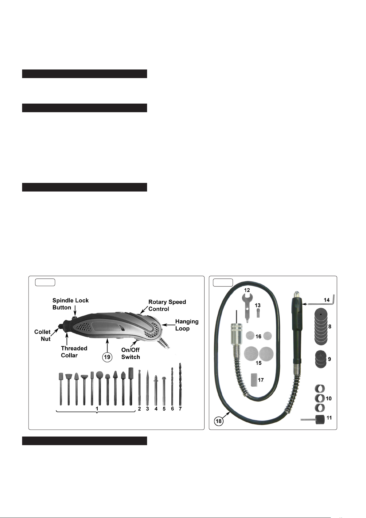
MULTI-PURPOSE ROTARY TOOL & ENGRAVER
KIT
MODEL No: E540.V3
1. SAFETY
1.1. ELECTRICAL SAFETY
WARNING! It is the user’s responsibility to check the following:
Check all electrical equipment and appliances to ensure that they are safe before using. Inspect power supply leads, plugs and
all electrical connections for wear and damage. Sealey recommend that an RCD (Residual Current Device) is used with all electrical
products. You may obtain an RCD by contacting your local Sealey stockist.
If the product is used in the course of business duties, it must be maintained in a safe condition and routinely PAT (Portable
Appliance Test) tested.
Electrical safety information, it is important that the following information is read and understood.
1.1.1. Ensure that the insulation on all cables and on the appliance is safe before connecting it to the power supply.
1.1.2. Regularly inspect power supply cables and plugs for wear or damage and check all connections to ensure that they are secure.
1.1.3. Important: Ensure that the voltage rating on the appliance suits the power supply to be used and that the plug is tted with the
correct fuse - see fuse rating in these instructions.
8DO NOT pull or carry the appliance by the power cable.
8DO NOT pull the plug from the socket by the cable. Remove the plug from the socket by maintaining a rm grip on the plug.
8DO NOT use worn or damaged cables, plugs or connectors. Ensure that any faulty item is repaired or replaced immediately by a
qualied electrician.
1.1.4. This product is tted with a BS1363/A 13 Amp 3 pin plug.
If the cable or plug is damaged during use, switch the electricity supply and remove from use.
Replace a damaged plug with a BS1363/A 13 Amp 3 pin plug. If in doubt contact a qualied electrician.
Class II products are wired with live (brown) and neutral (blue) only are marked with the
Class II symbol;
A) Connect the BROWN live wire to the live terminal ‘L’.
B) Connect the BLUE neutral wire to the neutral terminal ‘N’.
C) After wiring, check that there are no bare wires and ensure that all wires have been correctly connected.
Ensure that the cable outer sheath extends inside the cable restraint and that the restraint is tight.
DO NOT connect either wire to the earth terminal.
Sealey recommend that repairs are carried out by a qualied electrician.
1.2 GENERAL SAFETY
Only power the tool from the mains supply.
Disconnect the tool from the mains supply before changing accessories, servicing or performing any maintenance.
Maintain tool and accessories in good condition. Check moving parts and alignment. If necessary use an authorised service agent.
Replace or repair damaged parts using recommended parts. Unauthorised parts may be dangerous and will invalidate the warranty.
Wear approved safety eye protection with side shields and a dust mask if generating dust.
Remove ill fitting clothing. Remove ties, watches, rings and other loose jewellery and contain long hair.
Use the tool in a suitable working area, keep area clean and tidy and free from unrelated materials and ensure that there is adequate lighting.
Prevent body contact with earthed surfaces to avoid electric shock e.g. pipes, radiators, refrigerators etc.
Maintain correct balance and footing.
Keep children and unauthorised persons away from the working area.
Secure unstable workpiece with a clamp, vice or other adequate holding device.
Avoid unintentional starting. Keep the tool clean for best and safest performance.
When not in use switch tool off and unplug it from the mains supply. Store it in the case and put in a dry, childproof area.
DO NOT operate the tool if any parts are missing or damaged as this may cause failure and/or personal injury.
DO NOT operate the tool when you are tired or under the influence of alcohol, drugs or intoxicating medication.
DO NOT over-reach. Ensure the floor is not slippery and wear non-slip footwear.
DO NOT use the tool for a task it is not designed to perform.
DO NOT carry the tool by the cable.
Recommended fuse
rating:3A

DO NOT operate tool where there are flammable liquids or gases.
DO NOT hold unsecured work in your hand.
DO NOT get the tool wet or use in damp or wet locations.
DO NOT leave the tool running unattended.
NOTE: This appliance is not intended for use by persons (including children) with reduced physical, sensory or mental capabilities or lack of
experience and knowledge, unless they have been given supervision or instruction concerning the use of the appliance by a person responsible
for their safety. Children should be supervised to ensure that they do not play with the appliance.
2. INTRODUCTION
Multipurpose high-speed power tool with on/off and electronic variable speed controls. Stepless control between 10,000 and 32,000rpm. Spindle
lock for fast tool changes. Supplied with a full range of tips, wheels, sanding discs/bands, dressing stone, chuck spanner and exible rotary
shaft. Suitable for carving, shaping, de-burring, drilling, engraving, cutting and tool sharpening. Supplied in carry-case.
3. SPECIFICATION
Model No:................................................................................................................................. E540.V3
Motor Power - Supply......................................................................................................... 135W - 230V
Speed Range ........................................................................................................... 10000 to 32000rpm
Collet Capacities .......................................................................................................... 2.3mm and 3mm
Twist Drills .................................................................................................................... 2.3mm and 3mm
Mounted Points ..............................................................................................................................10pcs
Diamond Tipped Engraving Heads...................................................................................................2pcs
Sanding Cylinder.......................................................................................................... 12.7mm x 15mm
Accessories....................................................... Sanding bands (4pcs), Sanding discs (3pcs), Spanner
Cutting Discs (8pcs), Polishing Wheels (4pcs) Dressing Stone
4. CONTENTS
5. OPERATION
5.1. Fitting Accessories
5.1.1. Ensure the tool is switched off and unplugged from the mains supply.
5.1.2. Press the spindle lock button and slowly turn the collet nut until the spindle lock engages. Refer to Fig.1.
5.1.3. Retain pressure on the spindle lock button and turn the collet nut anticlockwise to open the collet.
NOTE: Never press the spindle lock button when the tool is running.
5.1.4. The required accessory may now be tted into the collet. Fully insert the accessory shaft to reduce the risk of bending in use.
Tighten the collet nut rmly. Finally, release the spindle lock button.
3.1 Refer to fig.1 and 2.
1) 10 Point Grinding wheel set...................... E540.V2-ACC1
2) Spherical diamond cutter. ......................... E540.V2-ACC2
3) Tapered diamond cutter. ........................... E540.V2-ACC3
4) Mandrel for felt wheel. .............................. E540.V2-ACC4
5) Mandrel for cut-off wheel. ......................... E540.V2-ACC5
6) HSS twist drill (2.3mm) ............................. E540.V2-ACC6
7) HSS twist drill (3mm). ............................... E540.V2-ACC7
8) Cut-off wheels........................................... E540.V2-ACC8
9) Sanding discs (20 x 0.35mm). ...................... E540.V2-ACC9
10) Sanding band (12.7 x 12.7mm)........................... E540.V2-ACC10
11) Sanding shank (12.7 x 12.7mm)................................E540.V2-ACC11
12) Spanner (9.7mm). ...................................E540.V2-ACC12
13) Brass collet (2.3mm). ..............................E540.V2-ACC13
14) Flexible drive locking bar. ........................E540.V2-ACC14
15) Felt wheel (22 x 7mm).............................E540.V2-ACC15
16) Felt wheel 12.7 x 7mm)...........................E540.V2-ACC16
17) Dressing stone (20 x 10 x 10mm). ....................... E540.V2-ACC17
18) Flexible extension drive...........................E540.V2-ACC18
19) Motor unit. ........................................................E540.V3-G
Fig. 1 Fig. 2
E540.V3 Issue: 3(4) - 03/09/18
Original Language Version
© Jack Sealey Limited

Sealey Group, Kempson Way, Suffolk Business Park, Bury St Edmunds, Suffolk. IP32 7AR
01284 757500 01284 703534 sales@sealey.co.uk www.sealey.co.uk
Note: It is our policy to continually improve products and as such we reserve the right to alter data, specifications and component parts without prior
notice.
Important: No Liability is accepted for incorrect use of this product.
Warranty: Guarantee is 12 months from purchase date, proof of which is required for any claim.
WEEE REGULATIONS
Dispose of this product at the end of its working life in compliance with the EU Directive on Waste Electrical and Electronic Equipment
(WEEE). When the product is no longer required, it must be disposed of in an environmentally protective way. Contact your local solid
waste authority for recycling information.
ENVIRONMENT PROTECTION
Recycle unwanted materials instead of disposing of them as waste. All tools, accessories and packaging should be sorted, taken to
a recycling centre and disposed of in a manner which is compatible with the environment. When the product becomes completely
unserviceable and requires disposal, drain any fluids (if applicable) into approved containers and dispose of the product and fluids
according to local regulations.
6. MAINTENANCE
6.1. Cleaning. Keep the tool ventilation slots clean and free from obstructions. If available, blow compressed air into the vents to clear any
internal dust. Safety goggles MUST be worn when undertaking this process.
Keep the drill outer case clean and free from grease. Wipe it down with a damp cloth.
DO NOT wash with water or use solvents or abrasives.
5.2. Changing collets
5.2.1. To change collets, proceed as in paragraphs 5.1.1. to 5.1.3. but continue to unscrew the collet nut until it can be removed from the
spindle. Change collets and replace the collet nut.
5.3. Operation
5.3.1. Select the speed required on the rotary speed control. Refer to Fig.1. Small accessories require high speed and large accessories
low speed. If in doubt, start on a low setting and gradually increase the speed until the best performance is obtained.
5.3.2. NOTE: DO NOT switch ON with a tool bit touching the workpiece. Always allow a bit to reach required speed before applying it
to the workpiece.
5.4 Flexible extension drive
5.4.1. Ensure the tool is switched off and unplugged from the mains supply.
5.4.2. To connect the exible drive extension pull the drive shaft out of the aluminium connector by about 30mm as shown in Fig.2.
5.4.3. Unscrew the black threaded collar from the drive end of the motor unit. See Fig.1.
5.4.4. Press the spindle lock button and slowly turn the collet nut until the spindle lock engages. Refer to Fig.1.
5.4.5. Retain pressure on the spindle lock button and turn the collet nut anticlockwise to open the collet.
5.4.6. Insert the drive shaft into the collet and hand tighten the collet nut. Further tighten the nut using the spanner provided. See Fig.2-12.
5.4.7. Bring the extension drive connector up to the thread on the motor unit and screw it fully on clockwise.
5.4.8. At the other end of the exible drive insert the locking bar (Fig2.14) into the hole in the drive head as indicated in Fig.2. Turn the collet
nut clockwise until the locking bar slides into the hole in the shaft and locks it.
5.4.9. Turn the collet nut anti-clockwise to loosen the collet and insert the required accessory. Hand tighten the collet nut and then further
tighten it using the spanner provided. See Fig.2-12.
5.4.10. Remove the locking bar.
5.4.11. Position yourself, ready for work, holding the drive head rmly before turning the motor unit on.
E540.V3 Issue: 3(4) - 03/09/18
Original Language Version
© Jack Sealey Limited
Table of contents
Other Sealey Power Tools manuals

Sealey
Sealey PS982.V2 User manual

Sealey
Sealey SB972.V4 User manual

Sealey
Sealey Power TOOLS PREMIER SA95.V3 User manual

Sealey
Sealey YC10B.V3 User manual

Sealey
Sealey AK2941 User manual

Sealey
Sealey SA92.V3 User manual

Sealey
Sealey AK2970 User manual

Sealey
Sealey AB933 User manual

Sealey
Sealey YK20F User manual

Sealey
Sealey GSA634 User manual

Sealey
Sealey SB974.V5 User manual

Sealey
Sealey AK623 User manual

Sealey
Sealey YK20FAH.V2 User manual

Sealey
Sealey VS9201.V2 User manual

Sealey
Sealey Vs0202 User manual

Sealey
Sealey YK20FAH.V3 User manual

Sealey
Sealey STW802 User manual

Sealey
Sealey AK7062 User manual

Sealey
Sealey STW305 User manual

Sealey
Sealey SA21/S User manual