Sealey BT2011 User manual

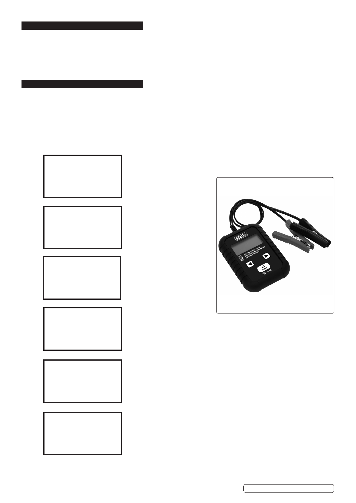
DIGITAL START/STOP BATTERY & ALTERNATOR/
STARTER TESTER
MODEL NO: BT2011
Thank you for purchasing a Sealey product. Manufactured to a high standard, this product will, if used according to these instructions,
and properly maintained, give you years of trouble free performance.
IMPORTANT: PLEASE READ THESE INSTRUCTIONS CAREFULLY. NOTE THE SAFE OPERATIONAL REQUIREMENTS, WARNINGS & CAUTIONS. USE
THE PRODUCT CORRECTLY AND WITH CARE FOR THE PURPOSE FOR WHICH IT IS INTENDED. FAILURE TO DO SO MAY CAUSE DAMAGE AND/OR
PERSONAL INJURY AND WILL INVALIDATE THE WARRANTY. KEEP THESE INSTRUCTIONS SAFE FOR FUTURE USE.
1. SAFETY
1.1. PERSONAL PRECAUTIONS
9Ensure that there is another person within hearing range and close enough to come to your aid, should a problem arise when working
near a lead-acid battery.
9Wear safety eye protection and protective clothing. Avoid touching eyes while working near battery.
9Have fresh water nearby in case battery acid contacts skin, clothing, or eyes.
9Rinse immediately with water if battery acid contacts skin or clothing. If acid enters eye, flush eye immediately with cool, clean
running water for at least 15 minutes and seek immediate medical attention.
9Remove personal metallic items such as rings, bracelets, necklaces and watches. A lead-acid battery can produce a short-circuit current
which is high enough to weld such items to the vehicle and cause severe burns.
9Ensure that hands, clothing (especially belts) are clear of fan blades and other moving or hot parts of engine. Remove ties and contain
long hair.
8DO NOT smoke or allow a spark or flame in the vicinity of the battery or engine.
1.2. GENERAL SAFETY INSTRUCTIONS
9Familiarise yourself with the application, limitations and potential hazards of the tester. Also refer to the vehicle manufacturer’s hand
book.
IF IN ANY DOUBT CONSULT A QUALIFIED ELECTRICIAN.
9Ensure that the tester is in good condition before use. If in any doubt DO NOT use the unit and contact a qualified electrician.
9Only use recommended attachments and parts. To use unapproved items may be dangerous and will invalidate your warranty.
9Keep tools and other items away from the engine and ensure that you can see the battery and working parts of the engine clearly.
9Determine the system voltage before using the tester.
9If the tester receives a sharp knock or blow the unit must be checked by a qualified service agent before using.
9If the battery terminals are corroded or dirty: clean them before using the tester.
9Keep children and unauthorised persons away from the work area.
8DO NOT dismantle the tester for any reason. The tester must only be checked by qualified service personnel.
WARNING! To prevent the risk of sparking, short circuit and possible explosion DO NOT drop metal tools in the battery area, or allow
them to touch the battery terminals.
8DO NOT cross-connect tester to battery. Ensure positive (RED) clamp is to positive terminal and negative (BLACK) clamp is to negative
terminal. If battery symbols cannot be distinguished: the negative terminal is the one directly connected to the vehicle bodywork.
8DO NOT use the tester outdoors, or in damp, or wet locations and DO NOT use in the vicinity of flammable liquids or gases.
8Ensure there is effective ventilation to prevent a build-up of explosive gases.
8DO NOT use the tester for a task for which it is not designed.
9When not in use, store the tester carefully in a safe, dry, childproof location.
2. INTRODUCTION
Robust and simple-to-use design oers a full in-vehicle diagnosis of the vehicle battery, starter motor and alternator in seconds. Professional
tool supports all 12V batteries including standard Lead-Acid, VRLA, GEL plus AGM and EFB found on all Start/Stop vehicles. The in-vehicle test
mode allows diagnosis of battery health, state of charge, internal resistance, cranking voltage and a comprehensive charging system voltage at
rest and under load. No heat, no sparks and no misdiagnosis. Equipped with reverse polarity protection and a battery temperature compensation
feature. A 4-Line/16 character LCD display gives easy to follow prompts and accurate results. Fitted with a heavy-duty rubber protection cover.
3. SPECIFICATION
Model no. ...................................................................BT2011
Charging system capability .........................................12/24V
Languages
............................ English, French, Spanish, German, Italian,
......................... Portuguese, Dutch, Russian, Turkish, Czech
Rated battery voltage.......................................................12V
Rating systems ................EN, JIS, DIN, IEC, CA(MAC), SAE
Voltage range............................................................... 8-30V
Original Language Version
© Jack Sealey Limited
Refer to
instructions
Wear eye
protection
Warning
corrosive
substance
Wear protective
clothing
Wear protective
gloves
Warning!
BT2011 | Issue:1 02/03/20

Original Language Version
© Jack Sealey Limited
4. TEST PREPARATION
4.1. Be sure area around battery is well ventilated while battery is being tested.
4.2. Clean battery terminals. Be careful to keep corrosion from coming in contact with eyes.
4.3. Inspect the battery for cracked or broken case or cover. If battery is damaged, DO NOT use tester.
4.4. If the battery is not sealed maintenance free, add distilled water in each cell until battery acid reaches level specied by the
manufacturer. This helps purge excessive gas from cells. DO NOT overll.
4.5. If necessary to remove battery from vehicle to test, always remove earth terminal from battery rst. Make sure all accessories in the
vehicle are o to ensure you do not cause any arcing.
5. OPERATION
NOTE: Each time you connect the tester to a battery, the tester will run a quick cable verication to ensure a proper connection
through the output cables to sensors in the clamp jaws. If the connection checks out OK, the tester will proceed to the Home Screen.
If the connection is poor, the display will show “CHECK CABLE”. In this case, check cable connections for visible signs of damage, as
you may need to re-connect the clamps to the battery or replace the cable end.
5.1. BEFORE TESTING:
5.1.1. Before you test a battery in a vehicle, turn o the ignition, all accessories and loads. Close all the vehicle doors and the boot/tailgate.
5.1.2. Make sure the battery terminals are clean. Wire brush them if necessary.
5.1.3. Clamp the black load lead to the vehicle negative battery terminal. Clamp the red load lead to the vehicle positive battery terminal.
Please clamp on the lead part of the terminal only. Clamping on the iron part of the terminal will lead to wrong test results.
5.2. MAIN MENU
View the following screens by pressing ◄/► to switch between all functions and settings.
Press ENTER to perform battery test.
Press ENTER to perform an alternator
test.
Press ENTER to perform a full in-vehicle test.
Press ENTER to change language.
Press ENTER to start adjusting screen brightness.
SYSTEM
ANALYSER
BATTERY TEST
XX.XX V
SYSTEM TEST
XX.XX V
IN-VEHICLE TEST
XX.XX V
LANGUAGE
SELECT
BRIGHTNESS
BT2011 | Issue:1 02/03/20

Original Language Version
5.3. BATTERY TEST
5.3.1. Select BATTERY TEST and press ENTER.
5.3.2. Press the ◄ ► to select REGULAR/STD or START/STOP battery.
REGULAR/STD BATTERY:
FLOODED, AGM FLAT PLATE, AGM SPIRAL, VRLA/GEL
START/STOP BATTERY:
AGM FLAT PLATE, EFB
5.3.3. Press the ◄ ► key to select the battery type.
5.3.4. Press ENTER to conrm choice.
5.3.5. Press the ◄ ► key to select the battery rating: CCA/SAE, EN, JIS, DIN, IEC & CA/MCA.
5.3.6. Press ENTER to conrm choice.
5.3.7. Press the ◄ ► key to input the battery capacity.
CCA/SAE: 40~2000
EN: 40~1885
DIN: 25~1120
IEC: 30~1320
JIS: By battery type no.
CA/MCA 50~2400
5.3.8. Press the ◄ ► to conrm the temperature.
5.3.9. Press ENTER to begin the test.
RETURN FEATURE:
Before the test is started, the user can return to the previous setting page by pressing ENTER
for 2 seconds.
5.3.10. SURFACE CHARGE:
The battery will hold a surface charge if the engine has been running or after the battery has been charged. The tester may prompt you to
remove the surface charge.
A. Follow the instructions indicating when to turn the headlights on and off or apply a load into the battery.
IN VEHICLE:
BATTERY TEST
XX.XX V
START/STOPREGULAR/STD
BATTERY TYPE:
AGM FLAT PLATE
SELECT RATING:
CCA/SAE
SELECT CAPACITY:
560CCA/SAE
ABOVE 32°F/0°C?
YES/NO
SURFACE CHARGE
IN VEHICLE? YES TURN HEADLIGHTS
ON FOR 15 SECS
© Jack Sealey Limited BT2011 | Issue:1 02/03/20

OUT OF VEHICLE:
B. The tester will resume testing after it detects that the surface charge is removed.
5.3.11. Test the battery for a few seconds.
5.3.12. Press the ◄►key to select battery fully charged or not if tester asks.
Press ENTER to confirm choice.
5.3.13. When the test is completed, the display shows the actual volts and the actual CCA and internal resistance. (Press the ◄ ►key to
read: SOH (STATE OF HEALTH) and SOC (STATE OF CHARGE)).
5.3.14. One of six test results will be displayed:
GOOD & PASS
* The battery is good and capable of holding a charge.
GOOD & RECHARGE
* The battery is good but needs to be recharged.
CAUTION
*The battery may be serviced but decrease the capability of starting the engine gradually.
The battery may fail under extreme climate conditions. There may be a poor connection between
the vehicle and the battery affect the charging function. Please pay attention to the battery for
replacement consideration and charging system checking.
RECHARGE & RETEST
* Battery is discharged, the battery condition cannot be determined until it is fully charged.
Recharge and retest the battery.
BAD & REPLACE
* The battery will not hold a charge. Replace immediately.
TESTING
SURFACE CHARGE
IN VEHICLE? NO
TESTING
IS BATTERY
CHARGED?
YES/NO
GOOD & PASS
VOL: XX.XX V
CCA: XXXX CCA /SAE
IR: XX.XXMΩ
GOOD & RECHARGE
VOL: XX.XX V
CCA: XXXX CCA /SAE
IR: XX.XXMΩ
CAUTION
VOL: XX.XX V
CCA: XXXX CCA /SAE
IR: XX.XXMΩ
RECHARGE & RETEST
VOL: XX.XX V
CCA: XXXX CCA /SAE
IR: XX.XXMΩ
BAD & REPLACE
VOL: XX.XX V
CCA: XXXX CCA /SAE
IR: XX.XXMΩ
BT2011 | Issue:1 02/03/20
Original Language Version
© Jack Sealey Limited

BAD CELL & REPLACE
* The battery has at least one cell short circuited. It should be replaced immediately.
LOAD ERROR
*The tested battery is bigger than 2000CCA/SAE or 200AH. Or the clamps are not connected
properly. Please fully charge the battery and retest after excluding both previous reasons.
If reading is the same, the battery should be replaced immediately.
5.3.15. SOC & SOH Display: Press directional keys to see SOC & SOH:
5.3.16. Press ENTER return to MAIN MENU or remove the test clamps from the battery posts after completion of testing the batteries
to end test.
5.4. SYSTEM TEST:
5.4.1. Select SYSTEM TEST from the main menu.
5.4.2. Turn off all vehicle accessory loads such as lights, air conditioning, radio etc,
before starting the engine.
5.4.3. When the engine is started, one of three results will be displayed along with the actual reading measured.
CRANKING VOLTS NORMAL
The system is showing normal draw. Press ENTER to perform the charging system test.
CRANKING VOLTS LOW
The cranking voltage is below normal limits.
Troubleshoot the starter according to the manufacturer's recommended procedure.
CRANKING VOLTS NOT DETECTED
The cranking voltage is not detected.
BAD CELL & REPLACE
VOL: XX.XX V
CCA: XXXX CCA /SAE
IR: XX.XXMΩ
LOAD ERROR
GOOD & PASS
SOC: XX.XX V
■ ■■■■■■■■□90%
GOOD & PASS
SOH : XX CCA/SAE
■ ■■■■■■■■□90%
SYSTEM TEST
XX.XX V
TURN OFF LOADS
START ENGINE
CRANKING VOLTS
XX.XX V NORMAL
CRANKING VOLTS
XX.XX V LOW
CRANKING VOLTS
NOT DETECTED
Original Language Version
© Jack Sealey Limited BT2011 | Issue:1 02/03/20

5.4.4. Press ENTER to begin charging system test.
5.4.5. Press the ENTER key, one of the three results will be displayed along with the actual reading measured.
HIGH CHARGING VOLTS WHEN TESTED AT IDLE
The voltage output from the alternator to the battery exceeds the normal limits of a functioning
regulator. Check to ensure there is no loose connection and the ground connection is normal.
If there is no connection issue, replace the regulator. Since most alternators have the regulator
built-in, this will require you to replace the alternator. The normal high limit of a typical automotive
regulator is 14.7 volts +/- 0.05. Check manufacturer's specifications for the correct limit, as it will
vary by vehicle type and manufacturer.
CHARGING SYSTEM NORMAL WHEN TEST AT IDLE
The system is showing normal output from the alternator. No problem is detected.
LOW CHARGING VOLTS WHEN TEST AT IDLE
The alternator is not providing sufficient current to the battery. Check the belts to ensure the
alternator is rotating with engine running. If the belts are slipping or broken, replace the belts and
retest. Check the connections from the alternator to the battery. If the connection is loose or
heavily corroded, clean or replace the cable and retest. If the belts and connections are in good
condition, replace the alternator.
5.4.6. Press ENTER for the charging system with accessory loads. Turn on the blower to high (heat),
high beam headlights, and heated rear window. Do not use cyclical loads such as air conditioning
or windshield wipers.
5.4.7. When testing older model diesel engines, run the engine up to 2500rpm for 15 seconds.
5.4.8. Press «ENTER» to read the ripple from the charging system to the battery. One of the three testing results will be displayed
along with the actual testing measured.
RIPPLE DETECTED NORMAL
Diodes function well in the alternator/starter.
NO RIPPLE DETECTED
Ripple is not detected.
PRESS ENTER FOR
CHARGING TEST
MAKE SURE ALL LOADS ARE
OFF
ALT. IDLE VOLTS
XX.XX V HIGH
ALT. IDLE VOLTS
XX.XX V NORMAL
ALT. IDLE VOLTS
XX.XX V LOW
TURN ON LOADS
PRESS ENTER
RUN ENGINE UP TO 2500RPM
15 SEC
RIPPLE
DETECTED
XX.XX V NORMAL
NO RIPPLE DETECT
PRESS ENTER
Original Language Version
© Jack Sealey Limited BT2011 | Issue:1 02/03/20

EXCESS RIPPLE DETECTED
One or more diodes in the alternator are not functioning or there is stator damage.
Check to ensure the alternator mounting is sturdy and that the belts are in good shape and
functioning properly. If the mounting and belts are good, replace the alternator.
5.4.9. Press the ENTER key to continue to test the charging system with accessory loads. One of three
results will be displayed along with the actual testing measured.
CHARGING SYSTEM HIGH WHEN TESTED WITH ACCESSORY LOADS
The voltage output from the alternator to the battery exceeds the normal limits of a functioning
regulator. Check to ensure there are no loose connections and that the ground connection is
normal. If there are no connection issues, replace the regulator. Since most alternators have the
regulator built-in, this will require you to replace the alternator.
CHARGING SYSTEM LOW WHEN TESTED WITH ACCESSORY LOADS
The alternator is not providing sufficient current for the system’s electrical loads and the charging
current for the battery. Check the belts to ensure the alternator is rotating with the engine running.
If the belts are slipping or broken, replace the belts and retest.
Check the connections from the alternator to the battery. If the connection is loose or heavily
corroded, clean or replace the cable and retest. If the belts and connections are in good working
condition, replace the alternator.
CHARGING SYSTEM NORMAL WHEN TESTED WITH ACCESSORY LOADS
The system is showing normal output from the alternator. No problem detected.
5.4.10. Press ENTER when charging system test is completed. Turn all accessory loads and engine off.
Press ENTER to read the system test results.
IN VEHICLE TEST
This is a combination test of both battery test and system test. Please refer to above testing procedures or follow the instructions on the
display of the tester.
GLOSSARY
What is a GEL battery?
A gel battery is a lead-acid electric storage battery that:
■ is sealed using special pressure valves and should never be opened.
■ is completely maintenance-free.
■ uses thixotropic gelled electrolyte.
■ uses a recombination reaction to prevent the escape of hydrogen and oxygen gases normally lost in a flooded lead-acid battery
(particularly in deep cycle applications).
■ is non-spillable, and therefore can be operated in virtually any position. However, upside-down installation is not recommended.
■ Connections must be re-torqued and the batteries should be cleaned periodically.
RIPPLE DETECTED
XX.XX V HIGH
ALT. LOAD VOLTS
XX.XX V HIGH
ALT. LOAD VOLTS
XX.XX V LOW
ALT. LOAD VOLTS
XX.XX V NORMAL
TEST OVER. TURN OFF
LOADS & ENGINE
ALT. LOAD VOLTS
XX.XX V NORMAL
RIPPLE VOLTAGE
XX.XX V NORMAL
CRANKING VOLTAGE
XX.XX V NORMAL
ALT. IDLE VOLTS
XX.XX V NORMAL
Original Language Version
© Jack Sealey Limited BT2011 | Issue:1 02/03/20

Sealey Group, Kempson Way, Suffolk Business Park, Bury St Edmunds, Suffolk. IP32 7AR
01284 757500 01284 703534 sales@sealey.co.uk www.sealey.co.uk
ENVIRONMENT PROTECTION
Recycle unwanted materials instead of disposing of them as waste. All tools, accessories and packaging should be sorted, taken to
a recycling centre and disposed of in a manner which is compatible with the environment. When the product becomes completely
unserviceable and requires disposal, drain any fluids (if applicable) into approved containers and dispose of the product and fluids
according to local regulations.
Note: It is our policy to continually improve products and as such we reserve the right to alter data, specifications and component parts without prior
notice.
Important: No Liability is accepted for incorrect use of this product.
Warranty: Guarantee is 12 months from purchase date, proof of which is required for any claim.
WEEE REGULATIONS
Dispose of this product at the end of its working life in compliance with the EU Directive on Waste Electrical and Electronic Equipment
(WEEE). When the product is no longer required, it must be disposed of in an environmentally protective way. Contact your local solid
waste authority for recycling information.
What is an AGM battery?
An AGM battery is a lead-acid electric storage battery that:
■ is sealed using special pressure valves and should never be opened.
■ is completely maintenance-free.*
■ has all of its electrolyte absorbed in separators consisting of a sponge-like mass of matted glass fibres.
■ uses a recombination reaction to prevent the escape of hydrogen and oxygen gases normally lost in a flooded lead-acid battery
(particularly in deep cycle applications).
■ is non-spillable, and therefore can be operated in virtually any position. However, upside-down installation is not recommended.
■ Connections must be retorqued and the batteries should be cleaned periodically.
What is a VRLA battery?
Valve Regulated Lead Acid Battery – This type of battery is sealed Maintenance Free with a “Bunce” Valve or Valves in the top of them
that opens when a preset pressure is realized inside the battery and let’s the excess gas pressure out. Then the valve resets itself.
What is a SLI battery?
These initials stand for Starting, Lighting and Ignition, which are the three basic functions which a battery has to perform on all
normal vehicles. Batteries given this description will have been specifically designed for service on cars and trucks within a
voltage controlled electrical system. Those SLI batteries which are intended for heavy haulage vehicles fitted with large diesel motors may
often be called COMMERCIAL batteries. They have to be much more powerful and more robust than batteries intended for cars.
What is STATE OF HEALTH?
It means how much battery capacity is left (%) comparing with the marked original battery capacity.
What is STATE OF CHARGE?
It means how many percent of the battery is actually charged.
What is CCA (COLD CRANKING AMPS)?
The current in amperes which a new fully charged battery can deliver for 30 seconds continuously without the terminal voltage falling
below 1.2volts per cell, after it has been cooled to 0OF and held at that temperature. This rating reflects the ability of the battery to deliver
engine starting currents under winter conditions.
What is AMPERE-HOUR?
The unit of measurement of electrical capacity. A current of one ampere for one hour implies the delivery or receipt of one ampere-hour.
Original Language Version
© Jack Sealey Limited BT2011 | Issue:1 02/03/20
Table of contents
Other Sealey Test Equipment manuals

Sealey
Sealey VS2030.V2 User manual

Sealey
Sealey TST22 User manual

Sealey
Sealey VS0033 User manual

Sealey
Sealey TA130 User manual

Sealey
Sealey VS2050 User manual

Sealey
Sealey VSE953 User manual

Sealey
Sealey VS0061.V2 User manual

Sealey
Sealey BT2002.V2 User manual

Sealey
Sealey TA319 User manual

Sealey
Sealey BT2101.V2 User manual

Sealey
Sealey TST22 User manual

Sealey
Sealey BT91/3.V2 User manual

Sealey
Sealey TA130.V2 User manual

Sealey
Sealey TA131 User manual

Sealey
Sealey BT2014 User manual

Sealey
Sealey BT91/7PF.V2 User manual

Sealey
Sealey VS8193 User manual

Sealey
Sealey AUTO SERVICE VSE206 User manual

Sealey
Sealey BT2012.V2 User manual

Sealey
Sealey BT91/1.V2 User manual