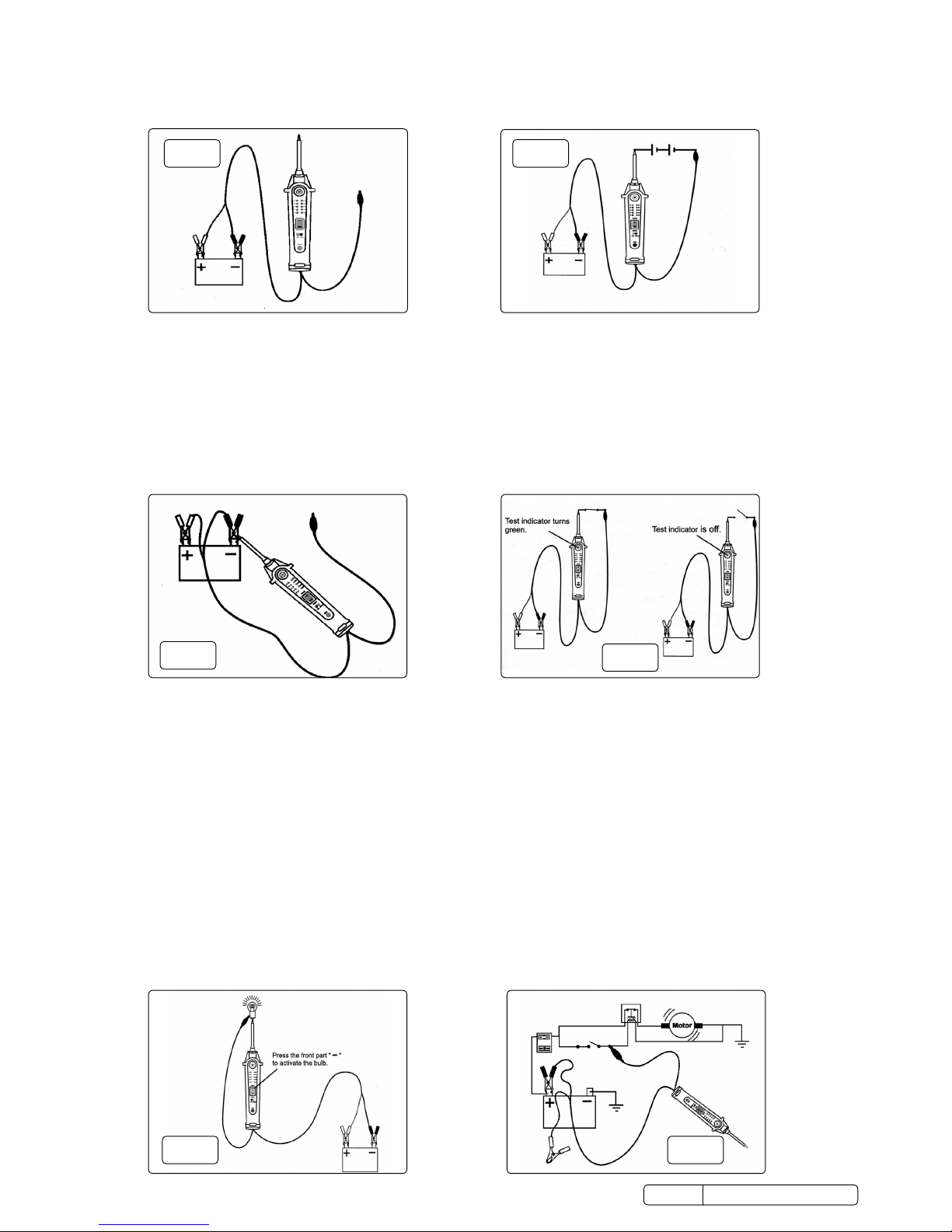
3.8. Activatingcomponentswithapositive(+)voltagewithinthevehicle’selectricalsystem(g.8).
3.8.1. Set the selection switch to ‘TEST’ position.
3.8.2. Contact the probe tip to the positive terminal, the test indicator should illuminate GREEN. Whilst observing the test indicator, quickly
press and release the power switch to the single bar ‘POSITIVE’ position.
3.8.3. Ifthetestindicatorwentoinstantly,theunithas beenoverloaded.Thiscouldhappenforthefollowingreasons:
a) The tip’s contact went to direct earth.
b) The component has a short circuit.
c) The component is a high current component (i.e. starter motor)
WARNING! Randomly applying voltage to certain circuits can cause damage to a vehicle’s electronic components. It is strongly
advised to use the correct circuit diagram and diagnostic procedures whilst performing this test.
3.9. Activatingcomponentswithanegative(-)voltagewithinthevehicle’sElectricalsystem(g.9).
3.9.1. Set the selection switch to ‘TEST’ position.
3.9.2. Contact the probe tip to the negative terminal of the component, the test indicator should illuminate RED. Whilst observing the test
indicator, quickly press the power switch to the double bar ‘NEGATIVE’ position and release it. If the indicator changes instantly from
RED to GREEN, you may proceed with further activation.
3.9.3. Iftheindicatorwentoinstantly,theunithasbeenoverloaded.Thiscouldhappenforthefollowingreasons:
a) Where the tip of the tester has contacted is a direct positive voltage.
b) The component has a short circuit.
c) The component is a high current component (e.g. a starter motor).
WARNING! With this function a vehicle’s fuses may blow when the probe tip is earthed in series with them.
3.10. CHECKING FOR BAD EARTH CONTACTS (g.10).
3.10.1. Set the selection switch to ‘test’ position.
3.10.2. Probe the suspected earth wire or contact with the probe tip. Observe the colour of the test indicator.
3.10.3. Press the power switch to the single bar ‘POSITIVE’ position and release it. If the test indicator changes from GREEN to RED, this is not
a true earth.
3.10.4. Ifthetestindicatorturnedowhenthepowerswitchwaspressedtothesinglebarposition,thiscircuitismorethanlikelyadirect
earth.Notethathighcurrentcomponentssuchasastartermotorwillalsocausethetestindicatortoturnoduringthischeck.
3.11. Following and locating short circuits. In most cases a short circuit causes a fuse to blow. This is the best place to commence the fault
ndingprocess.
3.11.1. Set selection switch to ‘TEST’ position.
3.11.2. Remove the blown fuse from the fuse box. Hold the probe tip against each of the contacts in turn whilst moving the power switch to the
forward,singlebar‘POSITIVE’position.Thesideofthefusehousingwhichcausesthetestindicatortoturnowhenthepowerswitch
is pressed forward is the shorted circuit.
3.11.3. Makeanoteofthiswire’sidenticationcodeorcolour.Followthewireasfarasyoucanalongthewiringharness.
3.11.4. Locate the colour coded wire in the harness and expose it as much as possible.
3.11.5. Probe through the insulation of the wire with the probe tip and move the power switch to the forward, single bar ‘POSITIVE’ position to
energisethewire.Ifthetestindicatorturnso,thiswirecanbeidentiedastheshortedwire.
3.11.6. Continuetestingthewireateachconnectorintheharness.Theconnectorwhichcausesthetestindicatortoturnowillleadyouto
theshortedarea.Inspecttheharnessforsignsofchangorburntoutwiringandreplaceorrepairasnecessary.
fig.8fig.9
PPVT Issue 2 (H, F) 23/02/18
Original Language Version
© Jack Sealey Limited
fig.10