INSTRUCTIONS FOR:
INFRARED TWIN-SPOT LASER DIGITAL
THERMOMETER 12:1
Model No: VS905
1. SAFETY
2. INTRODUCTION/SPECIFICATION
1.1. GENERAL SAFETY
WARNING! Ensure that Health & Safety, local authority and general workshop practice regulations are adhered to when
using this equipment.
WARNING! DO NOT aim the laser beams at your or another person’s or animal’s eye and beware of reflections from
mirrors or other shiny surfaces.
Familiarise yourself with the applications, limitations, and potential hazards of the thermometer.
Keep the thermometer clean and in good condition.
Protect the thermometer from the following:
- Electro-magnetic fields from engine components closer than 125mm.
- Static electricity.
- Thermal shock caused by large and/or rapid ambient temperature change.
- High temperatures.
DO NOT get the thermometer wet or use in damp or wet locations or areas where there is condensation.
DO NOT use the thermometer for any purpose other than that for which it is designed.
DO NOT allow untrained persons (particularly children) to operate the thermometer.
DO NOT operate the thermometer when you are tired or under the influence of alcohol, drugs or intoxicating medication.
WARNING! The warnings, cautions and instructions discussed in this instruction manual cannot cover all possible `
conditions and situations that may occur. It must be understood that common sense and caution are factors which cannot
be built into this product, but must be applied by the operator.
SPECIFICATION
Temperature Range ................... -50 to 550°C (-58 to 1022°F)
Ambient Operating Range ...................0 to 50°C (32 to 122°F)
Response Time ........................................150ms
Spectral Response .....................................8~14um
Assumes ambient operating temperature of 23 to 25°C (73 to 77°F).
Target Temperature .................................Accuracy
-50 to -20°C (-58 to 68°F) ..........................±2.5°C (4.5°F)
20 to 300°C (68 to 572°F) ......................±1% ±1.0°C (1.8°F)
300°C to 550°C (572 to 1022°F) ...........................± 1.5%
Over Range Indication . . . . . . . . . . . . . . . . . . . . . . . . . LCD will show ‘----’
Diode Laser ...........Output <1mW, Wavelength 630-670nm Class ll
Operating Temp. ...........................0 to 50°C (32 to 122°F)
Storage Temp. ............................0 to 60°C (14 to 140°F)
Relative Humidity ...........10%~90%RH operating, <80%RH storage
Battery ..................................................9V
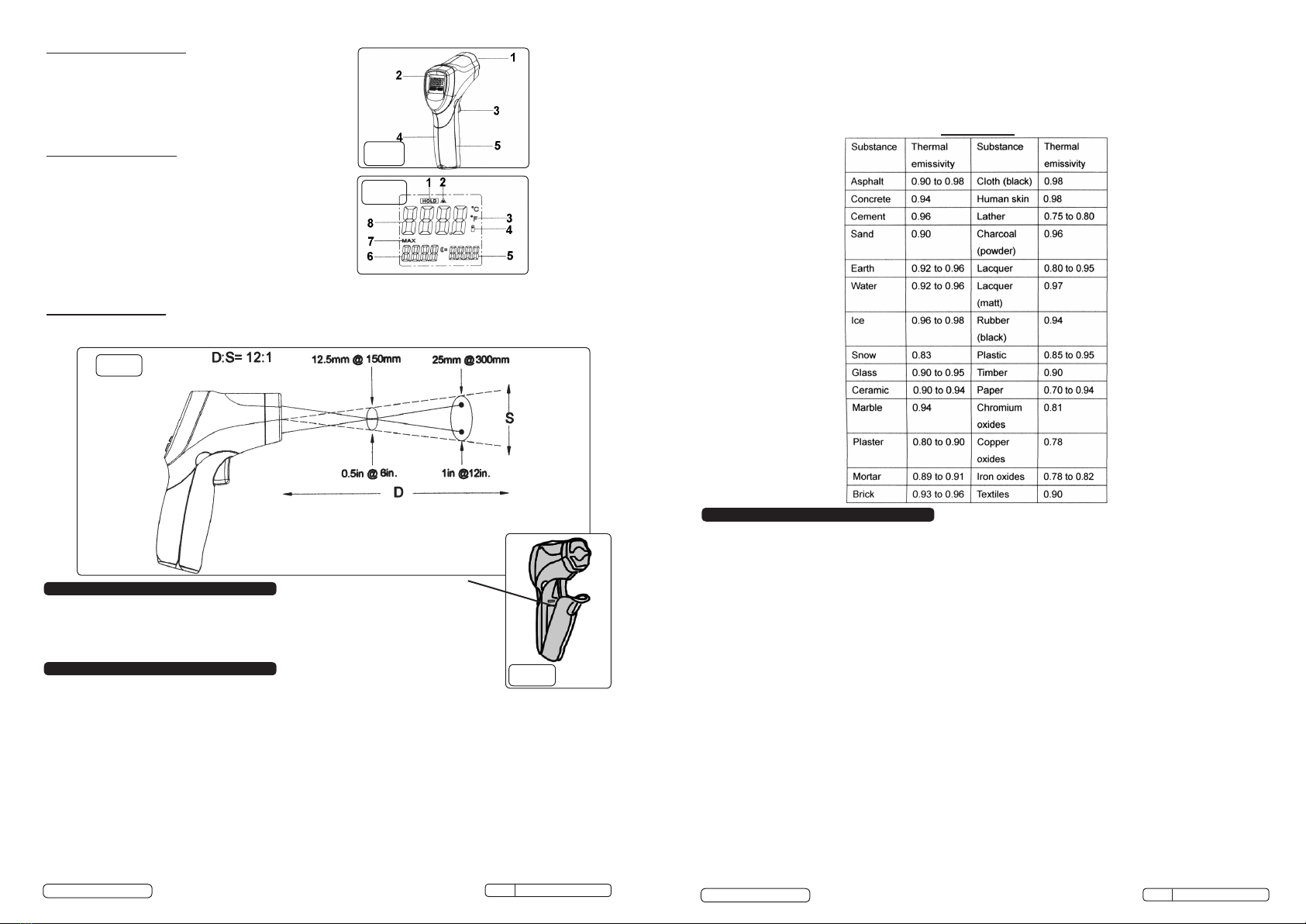
High resolution laser thermometer suitable for a wide range of garage and workshop applications. Twin-spot laser targeting
enables accurate readings by guiding user to the unit’s optimum targeting distance - when the two laser dots merge into one,
unit is reading a 13mm disc of temperature. This makes the unit especially suited for work where space is at a premium and
accurate focus on the target is required such as in engine bays and on circuit boards. Temperature is displayed on back-lit LCD
screen which features hold function for ease of use. Temperature can be shown in either °C or °F. Powered by 9Volt PP3
battery. Supplied with belt pouch.
1.2. LASER SAFETY
The VS905 utilises a Class II laser that emits low levels of visible radiation (i.e. wavelengths between 400 and 700 nanometres)
which are safe for the skin but not inherently safe for the eyes. The Class II emission limit is set at the maximum level for which eye
protection is normally afforded by natural aversion responses to bright light. Accidental eye exposure is therefore normally safe,
although the natural aversion response can be overridden by deliberately staring into the beam, and can also be influenced by the
use of alcohol or drugs.
WARNING! DO NOT look or stare into the laser beam as permanent eye damage could result.
DO NOT direct the laser beam at any person’s (or animal’s) eyes as eye damage could result.
DO NOT operate the thermometer when you are tired or under the influence of alcohol, drugs or intoxicating medication.
Be aware that reflections of the laser beam from mirrors or other shiny surfaces can be as hazardous as direct eye exposure.
6. MAINTENANCE
5.6. Catalytic Converter
With the engine at normal operating temperature and running at 1000rpm the
inlet of the catalytic converter should be cooler than the outlet by >55°C (2-way
converter) or >20°C (3-way converter).
1) If the outlet temperature is lower than the inlet then the converter is
‘plugged’ and must be replace.
2) If the outlet temperature is the same as the inlet then the converter has
reached the end of its service life (say 150,000 miles) or the converter
material has broken up due to damage or has become contaminated.
Always determine the cause of failure, and rectify if appropriate, before
fitting a replacement.
5.7. Brakes
The thermometer can be used to check comparative brake performance. The
brakes should be brought up to operating temperature, by braking the vehicle from
30mph to a halt five times in quick succession, and the brake disc/drum
temperatures then measured immediately. Brakes on the same axle should not
differ by more than 3°C and front brakes should be hotter than rear brakes by about
30°C. In the case of temperatures not meeting these criteria further investigation will
be required - noting that it is normally the cooler brake which is faulty (seized,
contaminated, etc.).
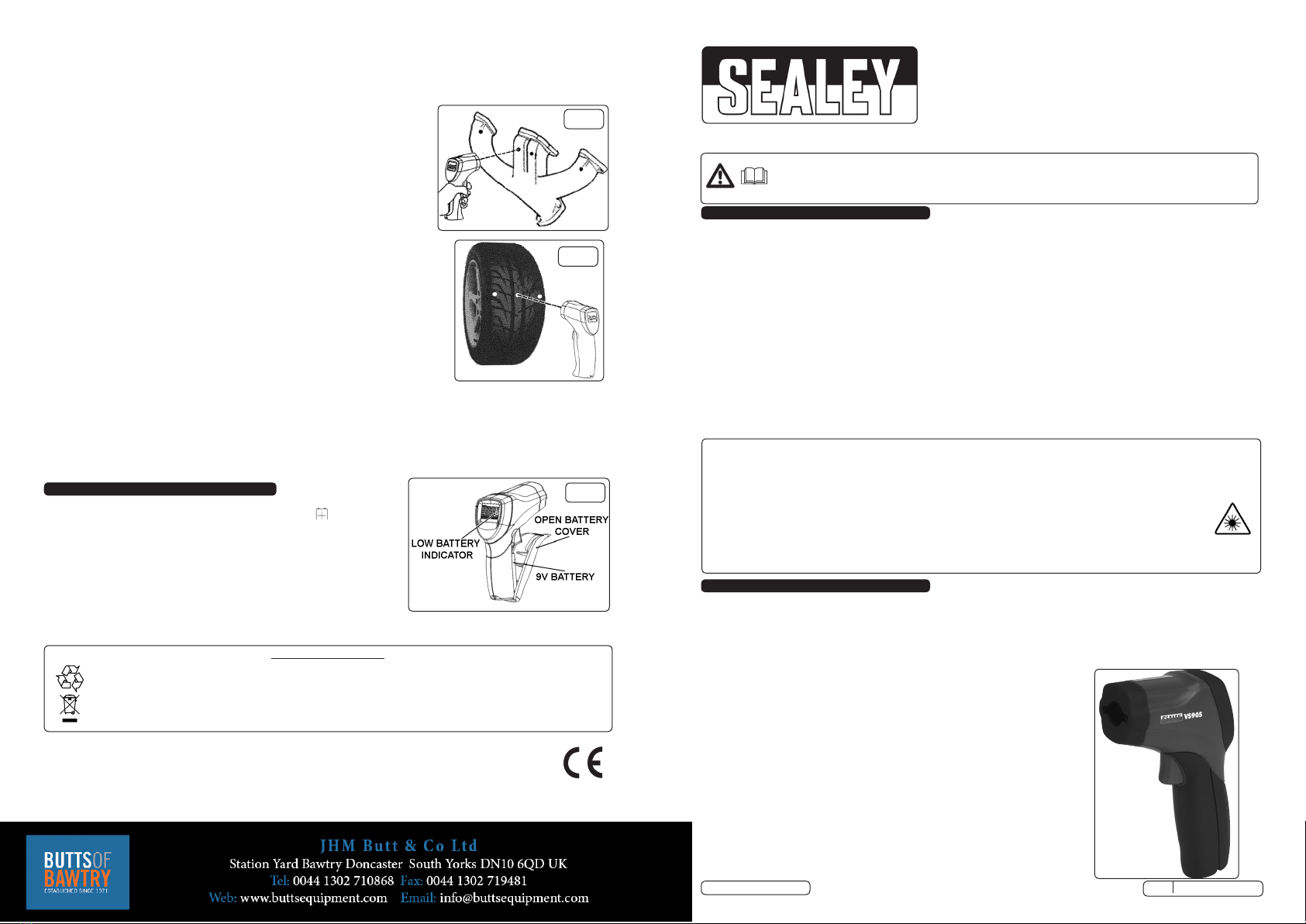
5.8. Tyres
A correctly inflated tyre will have the same temperature across the tread, within
10°C.
To check, drive the car for a few miles and then measure the tread in three places as
shown in fig.6. If the readings from the sides of the tread are higher than that from
the centre the tyre is probably under-inflated. Conversely over-inflation causes the centre to be hotter than the edges. In either
case, adjust the tyre pressure in 2psi steps until even temperatures are achieved. If the resulting pressure is significantly
different from that recommended by the vehicle/tyre manufacturer look for another cause of the temperature difference (worn,
damaged or misaligned suspension). Note that edge-of-tread temperatures which are significantly different from each other
indicate a suspension fault.
fig.6
5.5. Misfiring Cylinder
A misfiring cylinder (petrol or diesel) can be located by taking temperature readings of each branch of the exhaust manifold
(fig.5). The cool branch will indicate the misfiring cylinder. The temperature difference will be most marked before the engine
has warmed up and heat transfer has warmed the cool branch. One exhaust branch hotter than the rest (petrol) suggests
weak mixture to that cylinder, which should be investigated (faulty injector, inlet manifold gasket leak, etc.).
6.1. Battery Replacement (fig.7).
6.1.1. When the battery is exhausted the LCD will display the ‘ ‘ battery symbol.
6.1.2. Open the battery cover (fig.7) by pulling forward.
6.1.3. Replace the 9V(PP3) battery and snap the cover back into place.
6.2. Cleaning.
6.2.1. Use a damp cloth only to clean the casing.
6.3. Storage.
6.3.1. Store in a safe dry childproof location.
fig.5
fig.7
Environmental Protection
Recycle unwanted materials instead of disposing of them as waste. All tools, accessories and packaging should be sorted,
taken to a recycle centre and disposed of in a manner which is compatible with the environment.
When the product is no longer required, it must be disposed of in an environmentally protective way.
IMPORTANT: PLEASE READ THESE INSTRUCTIONS CAREFULLY. NOTE THE SAFE OPERATIONAL
REQUIREMENTS, WARNINGS & CAUTIONS. USE THE PRODUCT CORRECTLY AND WITH CARE FOR THE
PURPOSE FOR WHICH IT IS INTENDED. FAILURE TO DO SO MAY CAUSE DAMAGE AND/OR PERSONAL
INJURY AND WILL INVALIDATE THE WARRANTY. KEEP THESE INSTRUCTIONS SAFE FOR FUTURE USE.
Thank you for purchasing a Sealey product. Manufactured to a high standard, this product will, if used according to these
instructions, and properly maintained, give you years of trouble free performance.
NOTE: It is our policy to continually improve products and as such we reserve the right to alter data, specifications and component parts
without prior notice.
IMPORTANT: No liability is accepted for incorrect use of this product.
WARRANTY: Guarantee is 12 months from purchase date, proof of which will be required for any claim.
INFORMATION: For a copy of our latest catalogue and promotions call us on 01284 757525 and leave your full name and address,
including postcode.
Original Language Version
© Jack Sealey Limited VS905 Issue:2(L) - 04/08/14