manuals.online logo
Brands
  1. Home
  2. •
  3. Brands
  4. •
  5. Sealey
  6. •
  7. Tools
  8. •
  9. Sealey VS4980 User manual

Sealey VS4980 User manual

Jaguar: S-Type (99-08), XF (08-09), XJR (97-10), XJ8 (97-10),
XKR (98-09), XK8 (96-09), Sovereign (97-03)
Land Rover: Discovery III (04-09), Range Rover (05-09),
Range Rover Sport (05-09)
Daimler: V8 (97-03), Super V8 (97-03)
Engine Codes:
3.2: AC, KB, KC
3.5: RB
4.0: BC, CC, CE, DC, EC, GB, GC, LB,LC, MA, MB,
NB, NC, PA, PB
4.2: 1B, 2B, 3B, 1G, 5G, 9G, HB, HG, SB,TB, PC,
428PS
4.4: 448PN
INSTRUCTIONS FOR:
PETROL ENGINE SETTING/LOCKING KIT -
JAGUAR/LAND ROVER/DAIMLER - CHAIN DRIVE
MODEL No: VS4980
1. SAFETY 2. CONTENTS
3. APPLICATIONS
   WARNING! Ensure Health and Safety, local authority and
general workshop practice regulations are adhered to when
using tools.
   DO NOT use tools if damaged.
   Maintain tools in good and clean condition for best and safest
performance.
   Ensure that a vehicle which has been jacked up is adequately
supported with axle stands.
   Wear approved eye protection. A full range of personal safety
equipment is available from your Sealey dealer.
    Wear suitable clothing to avoid snagging. DO NOT wear
jewellery and tie back long hair.
    DO NOT attempt to start engine or move vehicle whilst in gear
with locking devices fitted.
Always display warning notification on steering wheel when
locking engine components.
    Account for all tools, locking bolts, pins and parts being used
and do not leave them in or near the engine.
WARNING! Incorrect or out of phase camshaft timing can result
in contact between valve head and piston crown causing
damage to the engine.
IMPORTANT: These instructions are provided as a guide only
Always refer to the vehicle manufacturer’s service instructions,
or a proprietary manual, to establish the current procedure and
data.
VS4980 Issue No: 3(SP) 08/07/15
VS4980
Associated Tool
VS4985
Original Language Version
© Jack Sealey Limited
Kit contains specialised tools required for timing chain setting and lock-
ing on Jaguar, Land Rover and Daimler 3.2, 3.5, 4.0, 4.2, 4.4 V8 AJ26/
AJ27/AJ28/AJ34 series petrol engines. Supplied with comprehensive
instructions and carry-case.
IMPORTANT: PLEASE READ THESE INSTRUCTIONS CAREFULLY. NOTE THE SAFE OPERATIONAL REQUIREMENTS, WARNINGS & CAUTIONS. USE THE PRODUCT
CORRECTLY AND WITH CARE FOR THE PURPOSE FOR WHICH IT IS INTENDED. FAILURE TO DO SO MAY CAUSE DAMAGE AND/OR PERSONAL INJURY AND WILL
INVALIDATE THE WARRANTY. KEEP THESE INSTRUCTIONS SAFE FOR FUTURE USE.
Thank you for purchasing a Sealey product. Manufactured to a high standard, this product will, if used according to these instructions
and maintained properly, give you years of trouble free performance.
Refer to
Instruction Manual
Wear Eye
Protection
 ThisV8petrolenginewasrstintroducedbyJaguarin1997and
is still in use today. Land Rover also started to use the later
versions of the engine in 2005. There have been many
changes, both in engine capacity and components over the
years, but most of the basic procedures for checking and
adjusting engine timing, dis-mantling and assembly of the
front-end gears, timing chain, camshafts etc., applies across the
engine range.
The timing applications on early and later engines are covered
by the VS4980 Engine Setting/Locking Tool Kit.
Timing adjustment and overhaul applications involving the front
end, gears, timing chains etc., require removal of the front timing
chain cover, and to remove this, the crankshaft pulley must be
removed.
On most variants the pulley bolt has a very high torque
 specicationandremovalandinstallationofthispulleyrequires
the Special Remover and Holding Tool in Set VS4985 –
Associated Tool.
IMPORTANT: References made to “left-hand bank” and “right-
hand bank” within this Product Information, refers to the left or
right cylinder heads as viewed from the front of the engine - ie.
from the camshaft gears.
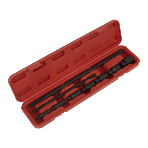
VS4980 Engine Setting/Locking Tool Kit
Comprises: VS4981 Flywheel Locking Pin (Silver)
VS4982 Flywheel Locking Pin (Gold)
VS4983 Camshaft Setting Plate Set (pair)
VS4984 Camshaft Gear Holding Tool
VS4986 Tensioner Wedge Set (Pair)
VS4975T8 Primary Tensioner Locking Pin
VS4593-1A Tensioner Depress Pin
VS4987 VVT Unit Setting Tool
VS4985 Crankshaft Pulley Remover/Installer Tool Set
Comprises: VS4921 Crankshaft Pulley Holding Tool
VS4922 Crankshaft Pulley Remover Set
4.1 Checking valve timing
To check that the valve timing is correct, a Flywheel Locking
 Toolmustbeinsertedto‘lock’theywheel(andthereforethe 
crankshaft), in timed position, and a Camshaft Setting Plate
 mustbeabletobexedinplaceacrossthe‘timingats’on
each bank of camshafts and rest fully on the surface of the
cylinder head.
“A” – VS4981 (early) / “B” – VS4982 (Late)
VS4981 Flywheel Locking Pin - Silver (early engines)
VS4982 Flywheel Locking Pin – Gold (later engines)
‘A’ ‘B’
4. INSTRUCTIONS
g.2
g.1
Associated Tools:
VS4985 Petrol Engine Crankshaft Pulley Removal/Installation
Kit - Daimler V8, Jaguar, Land Rover.
12
3
6
4
57
8
Original Language Version
© Jack Sealey Limited VS4980 Issue No: 3 (SP) 08/07/15
Item: Part No: Description: OEM No:
1VS4981 Flywheel Locking Pin (Silver) 303-531
2VS4982 Flywheel Locking Pin (Gold) 303-645
3VS4983 Camshaft Setting Plate Set
(2 per kit)
303-530
4VS4984 Camshaft Gear Holding Tool 303-532
5 VS4986 Tensioner Wedge Set (2 per kit) 303-533
6 VS4975TB Primary Tensioner Locking Pin -
7VS4593-1A Tensioner Depress Pin -
8 VS4987 VVT Unit Setting Tool 303-654
4.2.1 In order to check the camshaft timing the camshaft covers must
be removed.
4.2.2 Withthecrankshaftlockedin‘timed’positionthe‘timingats’ 
 (g.6a)onthecamshaftshouldbeuppermost.
4.2.3 One of the VS4983 Camshaft Setting Plates is placed across
 the‘timingats’ontheleft-handbankofcamshaftsandthe
 otherPlateislocatedacrossthe‘timingats’ontheright-hand
bank.
IMPORTANT: References made to left-hand bank and right-
hand bank are as viewed from the direction of the camshaft
gears.
4.2.4 In order for the camshaft timing to be correct, both Setting
Plates MUST t ush on to the camshaft ‘timing ats’ and
rest fully on the surface of the cylinder head (g.8).
If this cannot be achieved, then timing adjustment will be
necessary.
Timing adjustment and applications involving cylinder head/
camshaft removal will involve removal/installation of gears and
timing chains.
These applications require the front timing chain cover to be
removed, for access to gears, chains and tensioners, and to
remove the cover, the crankshaft pulley must be removed.
4.3 VS4985 Crankshaft Pulley Remover/Installer Tool Kit –
Associated Tool Set – not included in VS4980 Kit
The VS4985 Set comprises VS4921 Crankshaft Pulley Holding
 ToolandVS4922CrankshaftPulleyRemoverSet(g.9).
These tools must be used together when removing the
crankshaft pulley.
g.9
g.8
g.7
4.1.1 The shapes of these Flywheel Locking Pins match the
 appropriate‘timinghole’prolesintheywheel(g.3).
4.1.2 TheFlywheelLockingPinentersintotheywheel‘timinghole’
 throughthecrankshaftpositionsensorhole(g.4).Theposition
sensor is removed, and the Flywheel Locking Pin is inserted
 throughtheengine,intotheywheel(g.4a)andboltedin
position.
g.4a
WARNING: Under certain circumstances it may be possible
to insert the VS4982 Locking Pin for later engines into the
ywheel of early engines. However it will not feel a good,
positive t and it will not be possible to t the securing
screw for the Pin as the securing hole will be off-set (g.5).
If this occurs, remove and t VS4981 Pin.
4.2 VS4983 Camshaft Setting Plate Set (Pair)
g.6
g.5
g.3
g.4
g.6a
These two Flywheel Locking Pins cover the complete range of
engines.
 Theyarecolourcodedandforadditionalidenticationitcan 
 alsobeseening.2,thatVS4981(Silver)hastwoparallelat 
 faces,whereasVS4982(Gold)hasthreeatfaces.
Original Language Version
© Jack Sealey Limited VS4980 Issue No: 3 (SP) 08/07/15
4.4 VS4922 Pulley Remover Set – Removal of crankshaft pulley
NOTE: To remove the crankshaft pulley, the Holding Tool and
the Pulley Remover are assembled together onto the pulley.
The VS4921 Holding Tool is used to prevent the crankshaft
pulley from rotating whilst the force screw of the Pulley Remover
 isscrewedintoremovethecrankshaftpulley(g.14).
4.4.1 Pre-assemble the Bridge Piece, Force Screw and Securing
Bolts (the longer bolts in VS4895 Set) to make up the VS4922
Pulley Remover.
IMPORTANT: Insert the Thrust Plate into the centre hole of the
 pulley(g.15).
4.4.2 Screw the Guide Pin in to one of the threaded holes in the
 pulley(g.15a).
4.3.5 Using a breaker bar and socket, release the bolt of the
crankshaft pulley whilst counter-holding with the VS4921
 HoldingTool(g.13)
4.3.6 Undo the bolts attaching the VS4921 and remove the Holding
 Tool(g.13a).
4.4.3 Slide the VS4921 Holding Tool over the Guide Pin and into the
 recesstothepulley(g.16).
4.4.4 Attach the VS4922 Remover on to the Holding Tool, and to
the crankshaft pulley, by inserting one of the securing bolt
through the opposite hole to the Guide Pin (in the VS4921
Holding Tool), and into the crankshaft pulley threaded hole
 (g.16a).
g.14
g.15
g.16
g.15a
g.16a
The VS4922 Holding Tool is also used to counter-hold the
crankshaft pulley during installation.
WARNING: Some crankshaft pulley bolts require a torque
as high as 375Nm. making the tools in VS4895 Set an
essential part of the procedures requiring removal/
installation of the crankshaft pulley.
Crankshaft pulley removal
WARNING: The Flywheel Locking Pin MUST NOT be used
to counter-hold ywheel/crankshaft for releasing or
tightening the crankshaft pulley bolt as engine damage will
result.
4.3.1 VS4921 Crankshaft Pulley Holding Tool – releasing and
tightening pulley bolt.
The VS4921 Holding Tool is attached to the pulley using the
shorter securing bolts supplied in the Set. The bolts pass
through the Holding Tool and are screwed in to the threaded
holes in the pulley.
IMPORTANT: The threaded holes in the crankshaft pulley,
which accept the securing bolts, can be corroded or blocked.
Always check these threads and ensure they are clean and clear
to accept the securing bolts.
NOTE:Itcanbedifculttoalignthethreadedholesinthepulley
when attaching the Holding Tool, therefore utilise the Special
 GuidePinfromtheVS4922RemoverSet(g.11).
4.3.2 First, screw the Guide Pin into one of the threaded holes in the
pulley and then locate one of the holes in VS4921 Holding Tool
on to the Guide Pin and slide the Holding Tool in place in to the
 recessofthepulley(g.11a).
4.3.3 Insert a bolt in to the opposite hole in the Holding Tool and
 screwitintothepulley(g.12).RemovetheGuidePinand
 replaceitwiththesecondbolt,screwingintothepulley(g.12a).
4.3.4 Tighten both bolts, rmly, to secure the Holding Tool to the
crankshaft pulley.
g.11
g.10
g.12
g.11a
g.12a
g.13 g.13a
Original Language Version
© Jack Sealey Limited VS4980 Issue No: 3 (SP) 08/07/15
4.5.3 Screwinanewpulleysecuringbolttonger-tightonly.
4.5.4 Fit VS4921 Holding Tool to the crankshaft pulley and use it to
 counter-holdwhilsttighteningthesecuringbolttothespecied
 torquefortheenginevariantbeingworkedon(g.20).
4.5.5 If the pulley utilises a split locking ring–tanewo-ringseal
to the pulley and apply petroleum jelly to the bore and O-ring.
4.5.6 Fitthepulleyontothecrankshaftandtthesplitlockingring 
 insidetheboreofthepulley(g.21).
4.5.7 Screwinanewpulleysecuringbolttonger-tightonly(g.22).
4.5.8 Fit VS4921 Holding Tool to the crankshaft pulley and use it to
 counter-holdwhilsttighteningthesecuringbolttothespecied
 torquefortheenginevariantbeingworkedon(g.22a).
4.6 Adjusting valve timing
The following procedure covers valve timing adjustment and
also applies to setting up the valve timing when installing
camshafts, gears after cylinder head overhaul etc.
4.6.1 Check that the crankshaft is in its ‘timed’ position and that the
appropriate Flywheel Locking Pin has been inserted, as
described in “Checking valve timing”
4.6.2 Remove the water pump pulley.
4.6.3 Remove the front timing chain cover.
4.6.4 Remove the VVT solenoid housing from the inlet camshafts (if
 tted).
g.20
g.21
g.22
g.23
g.22a
4.4.5 Remove the Guide Pin and replace it with the second securing
bolt, passing it through Pulley Remover and the Holding Tool
 andintothethreadedholeofthepulley(g.17).
4.4.6 Tighten both bolts, rmly, to secure the Pulley Remover and
Holding Tool assembly to the crankshaft pulley.
4.4.7 Prevent the crankshaft pulley from rotating by counter-holding
with the VS4921 Tool. Screw in the Force Screw of the VS4922
 Removertoextractthepulleyoffthecrankshaft(g.18).
4.4.8 RemovetheThrustPlate(g.19),thecrankshaftpulleyandthe
 splitring(iftted)(g.19a).
4.5 Installing crankshaft pulley
IMPORTANT: The thread in the end of the crankshaft must
be cleaned out before installing a new pulley securing bolt. All
mating surfaces should be cleaned.
All except very early pulleys utilise a split locking ring.
4.5.1 If the pulley is a type without a locking ring - apply Loctite
648 to the bore of the crankshaft pulley. DO NOT apply to the
faces or to the crankshaft.
WARNING: The pulley must be tted and the securing bolt
fully tightened, within 7 minutes of the Loctite being
applied.
4.5.2 Fit the pulley to the crankshaft and wipe off any excess
Loctite.
g.19
g.18
g.17
g.19a
Original Language Version
© Jack Sealey Limited VS4980 Issue No: 3 (SP) 08/07/15
4.6.9 Remove VS4984 Holding Tool from the camshaft gear and
 slowlyturnthecamshaftstopositionthe‘timingats’to 
achieve the correct alignment to the Setting Plate. This will
allow the Camshaft Setting Plate to be bolted down, using the
securing bolts provided, in order that the Plate rests fully on
 thesurfaceofthecylinderhead(g.27).
WARNING: The camshaft ‘timing ats’ MUST BE in correct
alignment to the Setting Plates BEFORE the securing
screws of the Setting Plates are tightened down. The action
of tightening the securing screws of the Setting Plates
MUST NOT be used to turn the camshaft to position the
‘timing ats’ alignment, as damage to the cylinder head will
result.
4.6.10 Repeat this procedure on the other bank of camshafts.
NOTE:Discardtheoldcamshaftgearbolts–alwaystnew 
camshaft gear bolts.
WARNING: Tightening procedure for camshaft gear bolts:-
For early engines, Jaguar instructs that the EXHAUST
camshaft gear bolt is tightened rst, followed by the INLET
gear bolt.
However, for later engines Jaguar and Land Rover instruct
that the INLET camshaft gear bolts MUST BE tightened
before the EXHAUST gear bolts, and a WARNING is given
that failure to tighten the INLET camshaft gear bolts rst,
will result in engine damage.
4.6.11 Fit new bolts and use VS4984 Holding Tool to counter-hold the
exhaust camshaft gear. Tighten the new camshaft gear bolts to
 speciedtorque(g.28).
4.7 Removal of timing chains and gears.
Primary chains
4.7.1 Followtheprocedurefor“Checkingvalvetiming”,andtthe
appropriate Flywheel Locking Pin and the Camshaft Setting
Plates on both banks of camshafts.
4.7.2 Remove the crankshaft pulley following the procedure detailed
earlier.
4.7.3 Remove the front timing chain cover and the VVT control
 solenoidhousing,iftted.
4.7.4 Commenceworkontheleft-handbankrstastheprimarychain
from this bank is at the front of the crankshaft gear and therefore
 mustberemovedrsttoallowaccesstoremovetheother 
primary chain.
g.27
g.28
NOTE: In order for the camshaft timing to be correct, both
VS4983 Setting Plates MUST t ush on to the ‘timing ats’
and rest fully on the surface of the cylinder head.
4.6.5 To adjust the position of the camshafts to achieve this position
the inlet and exhaust camshaft gear bolts must be slackened.
Work on one bank of camshafts at a time.
4.6.6 Install an VS4983 Camshaft Setting Plate loosely across the
 ‘timingats’onthecamshafts.DO NOT tighten the securing
 boltsoftheSettingPlateatthisstage(g.24).
VS4984 Camshaft Gear Holding Tool
4.6.7 Fit VS4984 Camshaft Gear Holding Tool in to the holes in the
EXHAUST camshaft gear and use it to counter-hold whist
slackening the INLETcamshaftgearbolt(g.25).
4.6.8 Maintain VS4984 Holding Tool in this counter-holding position
and slacken the EXHAUSTcamshaftgearbolt(g.26).
NOTE:Itmaybenecessarytotabreakerbarintothesquare
drive provided in VS4984 Tool, to increase its counter-holding
leverage.
g.24
g.25
g.26
Original Language Version
© Jack Sealey Limited VS4980 Issue No: 3 (SP) 08/07/15
4.7.9 IMPORTANT: The crankshaft gear is a two piece gear - make a
note of the orientation of the gear teeth. The teeth of the left
hand bank crankshaft gear (front) must be out of phase to the
 teethoftherighthandbankgear(rear)(g.32).
Camshaft gears / Secondary chains
4.7.10 Remove the bolts of the inlet and exhaust camshaft gears and
 discardoldbolts(g.33).
4.7.11 Remove the gears, secondary chains and chain tensioners
 (g.34).
4.8 Installation chains and gears
NOTE: Early secondary chain tensioners must be
 de-pressurisedbeforere-tting.
Crankshaft gears
g.32
g.33
g.34
4.7.5 Fit VS4984 Holding Tool to the EXHAUST camshaft gear and
use to counter-hold whilst slackening the INLET camshaft gear
 bolt(g.29).Continuetocounter-holdandslackenthe 
 EXHAUSTcamshaftgearbolt(g.29a).
4.7.6 Removetheprimarychaintensionerunitandbackplate(g.30).
4.7.7 Removethechainguiderails(g.31)andtheprimarychain
 (g.31a).
4.7.8 Carry out the same procedure on the right-hand bank.
g.29
g.30
g.31
g.29a
g.31a
Original Language Version
© Jack Sealey Limited VS4980 Issue No: 3 (SP) 08/07/15
4.8.6 Install the primary chain on the right-hand bank (right-hand bank
primary chain is the rear chain on the crankshaft gear.
4.8.7 Fit the chain over the INLET camshaft gear and the crankshaft
 gear(g.39).
IMPORTANT: Ensure that there is NO SLACK on the drive
 sideofthechainandthattheVVTUnit(iftted),isNOT rotated
on the camshaft.
4.8.8 Check that slack is on the tensioner side of the chain.
 Re-tthechainguiderailsandtightentherailbolts.
Repeat this procedure on the left-hand bank camshaft gears.
4.9 EARLY ENGINES
Primary chain tensioners
NOTE: When installing the primary chain tensioners, ensure
 thatboththebackplateandtensionerunitarere-tted(g.40),
(the back plate creates the seal for the tensioner unit).
4.9.1 Insert VS4593-1A Depress Pin in to the centre of the tensioner
plunger and press the Pin to de-press the plunger in to its
 retractedposition(g.41).
g.39
g.40
g.41
g.36
4.8.1 Insert VS4593-1A Depress Pin, from Kit VS4980, in to the hole
 inthetensionertoallowtheplungertobedepressed(g.35).
4.8.2 Workingontheleft-handbank,re-tthesecondarychain
 tensionertotheengineandtightenbolts(g.36).
4.8.3 Re-tthecamshaftgearstogetherwiththesecondarychain. 
 Screwinnewgearbolts,nger-tightonly,allowingthegearsto
 turn,butnottilt(g.37).
4.8.4 Fit VS4984 Holding Tool and rotate and position the gears to
the most advantageous position in readiness for using the
Holding Tool when tightening the gear bolts (NOTE: once the
 primarychainistted,thecamshaftgearscannotbepositioned
 toassistToolpositioning(g.38).
4.8.5 Repeat this procedure on the right-hand bank camshaft gears.
g.35
g.37
g.38
Original Language Version
© Jack Sealey Limited VS4980 Issue No: 3 (SP) 08/07/15
4.9.8 Fit VS4987 to the VVT Unit and rotate the Unit anti-clockwise
to the fully retarded position.ThentVS4984HoldingToolto
the EXHAUST camshaft gear and apply force in an anti-
clockwise direction in order to ensure slack on the secondary
chain on the tensioner plunger side.
4.9.9 Whilst continuing to apply this force, tighten the INLET camshaft
gear bolt.
4.9.10 Repeat this procedure on the left-hand bank.
IMPORTANT: Remove all tools.
4.10 LATER ENGINES
Primary chain tensioners
These primary chain tensioners have a ratchet system on the
tensioner plunger.
WARNING: When compressing the plunger DO NOT release
the ratchet until the plunger has fully retracted into its bore
or damage to the ratchet system will result.
The plunger is compressed using a vice, and retained in this
position using VS4975T8 Locking Pin, from Kit VS4980.
4.10.1 Slowly compress the tensioner plunger using minimal force, and
insert VS4975T8 Locking Pin to retain the retracted plunger
position.
4.10.2 Fit the tensioner to the engine.
4.10.3 Pull out VS4975T8 Pin to actuate the plunger onto the chain rail.
Tightening camshaft gear bolts:-
4.10.4 Work on the right-hand bank.
IMPORTANT: On later engines, Jaguar and Land Rover
instruct that the INLET camshaft gear bolt is tightened rst,
followed by the EXHAUST gear bolt.
WARNING: On these engines the INLET camshaft gear bolt
MUST BE tightened before the EXHAUST camshaft gear
bolt. Failure to tighten the INLET camshaft gear bolts rst,
will result in engine damage.
4.10.5 Fit VS4984 to the EXHAUST camshaft gear and apply force, in
an anti-clockwise direction, to tension the primary chain on its
drive side, allowing the tensioner plunger to fully extend
outwards.
4.10.6 Whilst applying force with VS4984 Holding Tool, tighten the
 INLETgearboltrst,andthentightenEXHAUSTgearbolt
4.10.7 Repeat procedure on the left-hand bank.
01284 757500
sales@sealey.co.uk
www.sealey.co.uk
01284 703534
Web
NOTE: It is our policy to continually improve products and as such we reserve the right to alter data, specifications and component parts without prior notice.
IMPORTANT: No liability is accepted for incorrect use of this equipment.
WARRANTY: Guarantee is 12 months from purchase date, proof of which will be required for any claim.
.
4.9.4 TightentheEXHAUSTcamshaftgearbolt(g.44).
4.9.5 Fit VS4984 Holding Tool to the EXHAUST gear and apply force
to the Tool, in an anti-clockwise direction, in order to ensure
slack on the secondary chain on the tensioner plunger side.
4.9.6 Whilst applying this force, tighten the EXHAUST camshaft gear
bolt.
4.9.7 If engine does not have VVT, continue to apply force with
 VS4984andtightentheINLETcamshaftgearbolt(g.45).
VS4987 VVT Setting Tool
 Someearlyengines,arettedwithVTT,anditisnecessaryto
use VS4987 Setting Tool before tightening the INLET camshaft
gear bolt.
4.9.2 Fitthebackplateandtensionerunittotheengine(g.42).
VS4986 Tensioner Wedge Set
4.9.3 Fit the VS4986 Wedge between the tensioner plunger and the
 chainrailtollanygap,removingslackfromthechain(g.43).
NOTE: VS4986 is a pair of Tensioner Wedges and can be used
as a single Wedge or in a combination of two Wedges,
dependant upon the gap between plunger and rail.
g.42
g.43
g.44 g.45
Sole UK Distributor, Sealey Group,
Kempson Way, Suffolk Business Park,
Bury St. Edmunds, Suffolk,
IP32 7AR
Original Language Version
© Jack Sealey Limited VS4980 Issue No: 3 (SP) 08/07/15
Tightening camshaft gear bolts:-
IMPORTANT: On early engines, Jaguar instruct that the
EXHAUST camshaft gear bolt is tightened rst, followed by
the INLET gear bolt.
Environmental Protection
Recycle unwanted materials instead of disposing of them as waste. All tools, accessories and packaging should be sorted, taken to a recycling centre
and disposed of in a manner which is compatible with the environment. When the product becomes completely unserviceable dispose of it according to
local regulations.
Other Sealey Tools manuals

Sealey SA613 User manual

Sealey

Sealey SA613 User manual

Sealey SCR84.V2 User manual

Sealey

Sealey SCR84.V2 User manual

Sealey VS722.V3 User manual

Sealey

Sealey VS722.V3 User manual

Sealey DJ01 User manual

Sealey

Sealey DJ01 User manual

Sealey RE105 User manual

Sealey

Sealey RE105 User manual

Sealey VSE5586 User manual

Sealey

Sealey VSE5586 User manual

Sealey CPG12V.v3 User manual

Sealey

Sealey CPG12V.v3 User manual

Sealey Auto Service VS2046.V2 User manual

Sealey

Sealey Auto Service VS2046.V2 User manual

Sealey Auto Service VSE127H User manual

Sealey

Sealey Auto Service VSE127H User manual

Sealey SX206 User manual

Sealey

Sealey SX206 User manual

Sealey GA40 User manual

Sealey

Sealey GA40 User manual

Sealey AUTO SERVICE VS8626 User manual

Sealey

Sealey AUTO SERVICE VS8626 User manual

Sealey AUTO SERVICE OFC1 User manual

Sealey

Sealey AUTO SERVICE OFC1 User manual

Sealey VS0202.V2 User manual

Sealey

Sealey VS0202.V2 User manual

Sealey TD1202SR User manual

Sealey

Sealey TD1202SR User manual

Sealey ct610 User manual

Sealey

Sealey ct610 User manual

Sealey MK66.V3 User manual

Sealey

Sealey MK66.V3 User manual

Sealey SA401.V2 User manual

Sealey

Sealey SA401.V2 User manual

Sealey RE230 User manual

Sealey

Sealey RE230 User manual

Sealey Auto Service Line VSE6000 User manual

Sealey

Sealey Auto Service Line VSE6000 User manual

Sealey AK481 User manual

Sealey

Sealey AK481 User manual

Sealey VS7026.V2 User manual

Sealey

Sealey VS7026.V2 User manual

Sealey AK96SET User manual

Sealey

Sealey AK96SET User manual

Sealey AK3843 User manual

Sealey

Sealey AK3843 User manual

Popular Tools manuals by other brands

Jungle Jim’s JUNGLE JACK V2 Assembly instructions

Jungle Jim’s

Jungle Jim’s JUNGLE JACK V2 Assembly instructions

Gage Bilt GB512BOM Original instructions

Gage Bilt

Gage Bilt GB512BOM Original instructions

Rothenberger Ro-Groover 1-12 Instructions for use

Rothenberger

Rothenberger Ro-Groover 1-12 Instructions for use

Tempo Communications FCL100 instruction manual

Tempo Communications

Tempo Communications FCL100 instruction manual

BorMann PRO BDM6700 instructions

BorMann

BorMann PRO BDM6700 instructions

Graco SD Series instructions

Graco

Graco SD Series instructions

Hazet 2191/12 K operating instructions

Hazet

Hazet 2191/12 K operating instructions

Powell PowlVac 01.4IB.51051C Assembly

Powell

Powell PowlVac 01.4IB.51051C Assembly

Milescraft SawGuide 1403 instruction manual

Milescraft

Milescraft SawGuide 1403 instruction manual

RED ROOSTER RRI-BIM25T manual

RED ROOSTER

RED ROOSTER RRI-BIM25T manual

HOZAN С-426 instruction manual

HOZAN

HOZAN С-426 instruction manual

SIC U2W Series operating instructions

SIC

SIC U2W Series operating instructions

Kemper FROSTL-PLUS 574 Installation Manual preliminary installation

Kemper

Kemper FROSTL-PLUS 574 Installation Manual preliminary installation

Victaulic VE106 Groove-N-Go Operating and maintenance instruction manual

Victaulic

Victaulic VE106 Groove-N-Go Operating and maintenance instruction manual

Alice's Garden NW-H8315B quick start guide

Alice's Garden

Alice's Garden NW-H8315B quick start guide

infaco P8F120 Original instructions

infaco

infaco P8F120 Original instructions

Zhermack dune 2 Maintenance and use manual

Zhermack

Zhermack dune 2 Maintenance and use manual

Warner Instruments FC-0 manual

Warner Instruments

Warner Instruments FC-0 manual

manuals.online logo
manuals.online logoBrands
  • About & Mission
  • Contact us
  • Privacy Policy
  • Terms and Conditions

Copyright 2025 Manuals.Online. All Rights Reserved.