Sealey SA317.V2 User manual

AIR/HYDRAULIC NUT RIVETER
HEAVY-DUTY VACUUM SYSTEM
MODEL NO: SA317.V2
Thank you for purchasing a Sealey product. Manufactured to a high standard, this product will, if used according to these
instructions, and properly maintained, give you years of trouble free performance.
IMPORTANT: PLEASE READ THESE INSTRUCTIONS CAREFULLY. NOTE THE SAFE OPERATIONAL REQUIREMENTS, WARNINGS & CAUTIONS. USE
THE PRODUCT CORRECTLY AND WITH CARE FOR THE PURPOSE FOR WHICH IT IS INTENDED. FAILURE TO DO SO MAY CAUSE DAMAGE AND/OR
PERSONAL INJURY AND WILL INVALIDATE THE WARRANTY. KEEP THESE INSTRUCTIONS SAFE FOR FUTURE USE.
1. SAFETY
WARNING! Ensure health & safety, local authority, and general workshop practice regulations are adhered to when using this equipment.
9Familiarise yourself with this products application and limitations, as well as the specific potential hazards peculiar to the riveter.
WARNING! Disconnect the riveter from the air supply before changing accessories, servicing or performing any maintenance.
9Maintain the riveter in good condition (use an authorised service agent).
9Replace or repair damaged parts. Use genuine parts only. Unauthorised parts may be dangerous and will invalidate the warranty.
9Use in a suitable work area. Keep area free from unrelated materials and ensure that there is adequate lighting.
9Keep the riveter clean for best and safest performance.
WARNING! Always wear approved eye (or face) and hand protection when operating the riveter.
9Maintain correct balance and footing. DO NOT over reach, ensure the floor is not slippery, wear non slip shoes.
9Remove ill fitting clothing. Remove ties, watches, rings, and other loose jewellery and contain or tie back long hair.
9Wear appropriate protective clothing and keep hands and body clear or working parts.
9Keep the riveter away from your body and at a safe distance from others.
9Keep children and unauthorised persons away from the working area.
9Secure non stable work piece with a clamp, vice or other adequate holding device.
WARNING! ensure correct air pressure is maintained and not exceeded. Recommended pressure 100psi.
9Keep air hose away from heat, oil and sharp edges. Check air hose for wear before each use, and ensure that all connections are secure.
8DO NOT use the riveter for a task it is not designed to perform.
8DO NOT operate the riveter if any parts are damaged or missing as this may cause failure and/or personal injury.
8DO NOT carry the riveter by the hose, or yank the hose from the air supply.
8DO NOT get the riveter wet or use in damp/wet locations or areas where there is condensation.
8DO NOT allow untrained persons to operate the riveter.
8DO NOT operate the riveter when you are tired, under the influence of alcohol, drugs or intoxicating medication.
8DO NOT direct air from the air hose at yourself or others.
9When not in use disconnect from the air supply and store in a safe, dry, child proof location.
9Avoid unintentional starting.
2. INTRODUCTION
Heavy-duty, suitable for all types of nut rivets. Supplied with seven mandrels,
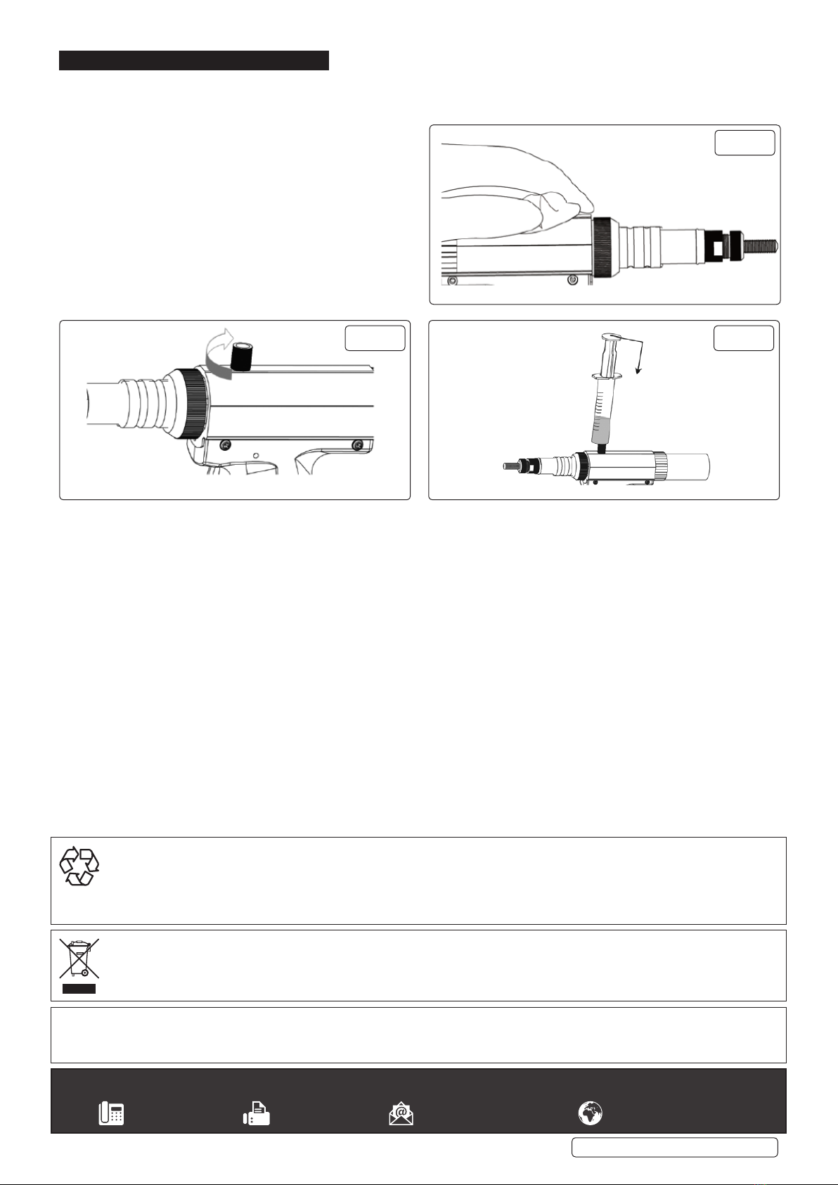
two spanners and oil syringe. Trigger operated with automatic wind release for
fast application. Will handle heavy assembly work.
3. SPECIFICATION
Model No: .................................................SA317.V2
Mandrel Size:...........M3, M4, M5, M6, M8, M10, M12
Air Consumption: ............................................ 4.5cfm
Operating Pressure:.........................................100psi
Air Inlet Size:.................................................1/4”BSP
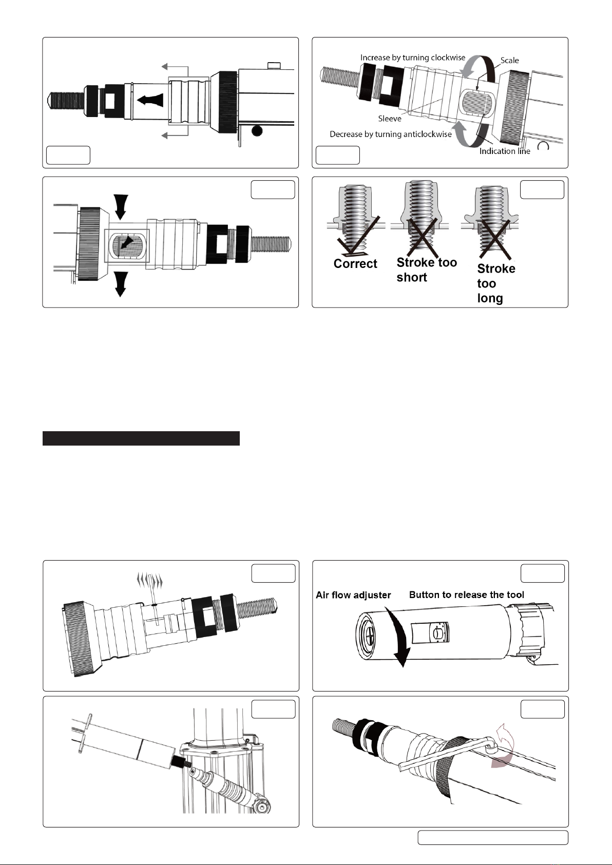
Stroke Range:................................................. 1-8mm
Nett Weight: ...................................................... 2.6kg
Noise Power/Pressure: ................... 89dB(A)/78dB(A)
Vibration/Uncertainty:............................. 1.2/0.61m/s²
4. AIR SUPPLY
WARNING! Ensure the air supply is clean and does not exceed 100psi
while operating the riveter. Too high an air pressure and unclean air will
cause excessive wear, and may be dangerous, causing damage and/or personal injury.
4.1. Ensure the riveter air valve (or trigger) is not depressed before connecting to the air supply.
4.2. You will require an air pressure between 70-100psi.
4.3. Drain the compressor daily. Water in the air line will damage the riveter and invalidate your warranty.
SA317.V2 | Issue 1 25/2/19
Original Language Version
© Jack Sealey Limited
Refer to
instructions
Wear eye
protection
Wear protective
gloves
Wear ear
protection

4.4. Clean air inlet filter weekly. Recommended hook-up procedure is shown in (fig.1).
4.5. Line pressure should be increased to compensate for unusually long air hoses (over 8 metres).
4.6. The minimum hose diameter should be 1/4” I.D., fittings must have the same inside dimensions.
4.7. Keep hose away from heat, oil and sharp edges. Check hoses for wear, and make certain that all connections are secure.
4.8. COUPLINGS
4.8.1. Vibration may cause failure if a quick change coupling is connected directly to the air riveter. To overcome this, connect a leader
hose - Sealey Model No: AH2R or AH2R/38 - to the riveter. A quick change coupling may then be used to connect the leader
hosetotheairlinerecoilhose(gs.1&2).
5. PREPARATION
5.1. MANDREL CHANGE
5.1.1. Select from M3 to M12. Lock nuts are all the same size for mandrel and anvil.
5.1.2. Removeanvilandlocknut(g.3).
5.1.3. Unscrewknurledcover(anticlockwise)andnosepedestal(g.4).
5.1.4. Pushbacktheslidingsleeveandunscrewthemandrel(g.5).OP
5.1.5. Selectrequiredmandrelasperrivetnutsize,pushbackslidingsleeveandscrewinselectedmandrelthenreleaseslidingsleeve(g.6).
5.1.6. Screw on knurled cover, nose pedestal, locknut and anvil.
5.2. MANDREL PROTRUSION SETTING FOR BLIND NUT
5.2.1. Set the length of the mandrel protruding out of the anvil, according to the blind rivet nut length. Undo the locknut and wind the anvil
in or out as required. Re-tighten the locknut.ER
5.2.2. Neversetthemandrelprotrudinglengthtoolongortooshortaccordingtotherivetnuttobeset(g.8).AT
SA317.V2 | Issue 1 25/2/19
Original Language Version
© Jack Sealey Limited
g.1 g.2
g.3 g.4
g.5 g.6
g.7 g.8

5.3. STROKE SETTING
5.3.1. Tool stroke should be set according to the thickness of the work piece into which the rivet nut is to be set. The tool’s stroke can be
adjustedbetween1mmand8mm.Pushthesleevetowardsthemandrel(g.9).IO
5.3.2. Adjustthetoolstrokebyturningtheknurledwheel(gs10&11).Thescalealongthewindowarethesettingsforstroke.Pushthe
sleeve back to its original position after setting.N
5.3.3. Toestablishaprecisestrokesetting,itisrecommendedtosetatrialrivetnut(g.12)andrepeattheoperationsuntilthestroke
has been correctly set.
5.3.4. In the case of the stroke being too long, it could be that the rivet nut can not be released from the mandrel after setting. To release
the tool from a damaged rivet nut use a piece of 3mm steel wire or equivalent, inserted into the hole on the nose pedestal. Turn it
clockwisetoreleasetherivetnut(g.13).
6. OPERATION
6.1. After preparation and stroke setting (see section 5), put the rivet nut into the pre-drilled work piece hole.
6.2. Insert the mandrel into the rivet nut, push the tool and the mandrel will be automatically turned into the rivet nut.
6.3. Pull the trigger to set the rivet into the work piece.
6.4. After setting the rivet nut, release the trigger and the mandrel will turn anticlockwise and the tool will be released from the set rivet nut.
6.5. In case the tool is still not released from the set rivet nut, press the red button at the back of the compressed spring pedestal, then
the tool will be released.
6.6. OPTIONALUSEOFAIRFLOWADJUSTER(g.14)
6.6.1. Theairowadjusterchangesthedirectionoftheairowreleasedfromthetoolduringoperationanddoesnotaffectperformance.
6.6.2. It can be directed to operator’s preference.
6.6.3. The red button can still be reached through the window to release the tool when necessary, see section 6.5.
g.9 g.10
g.11 g.12
g.13 g.14
g.15 g.16
SA317.V2 | Issue 1 25/2/19
Original Language Version
© Jack Sealey Limited

WARNING! – Risk of Hand Arm Vibration Injury.
This tool may cause Hand Arm Vibration Syndrome if its use is not managed adequately.
This tool is subject to the vibration testing section of the Machinery Directive 2006/42/EC.
This tool is to be operated in accordance with these instructions.
Measuredvibrationemissionvalue(a): ...........1.2 m/s²
Uncertaintyvalue(k):..........................0.61m/s²
Please note that the application of the tool to a sole specialist task may produce a different average vibration emission. We recommend that
a specific evaluation of the vibration emission is conducted prior to commencing with a specialist task.
A health and safety assessment by the user (or employer) will need to be carried out to determine the suitable duration of use for each tool.
NB: Stated Vibration Emission values are type-test values and are intended to be typical.
Whilst in use, the actual value will vary considerably from and depend on many factors.
Such factors include; the operator, the task and the inserted tool or consumable.
NB: ensure that the length of leader hoses is sufficient to allow unrestricted use, as this also helps to reduce vibration.
The state of maintenance of the tool itself is also an important factor, a poorly maintained tool will also increase the risk of Hand Arm Vibration
Syndrome.
Health surveillance.
We recommend a programme of health surveillance to detect early symptoms of vibration injury so that management procedures
can be modified accordingly.
Personal protective equipment.
We are not aware of any personal protective equipment (PPE) that provides protection against vibration injury that may result from the
uncontrolled use of this tool. We recommend a sufficient supply of clothing (including gloves) to enable the operator to remain warm and dry
and maintain good blood circulation in fingers etc. Please note that the most effective protection is prevention, please refer to the Correct Use
and Maintenance section in these instructions. Guidance relating to the management of hand arm vibration can be found on the HSE website
www.hse.gov.uk - Hand-Arm Vibration at Work.
SA317.V2 | Issue 1 25/2/19
Original Language Version
© Jack Sealey Limited
Sealey Group, Kempson Way, Suffolk Business Park, Bury St Edmunds, Suffolk. IP32 7AR
01284 757500 01284 703534 sales@sealey.co.uk www.sealey.co.uk
ENVIRONMENT PROTECTION
Recycle unwanted materials instead of disposing of them as waste. All tools, accessories and packaging should be sorted, taken to
a recycling centre and disposed of in a manner which is compatible with the environment. When the product becomes completely
unserviceable and requires disposal, drain any fluids (if applicable) into approved containers and dispose of the product and fluids
according to local regulations.
WEEE REGULATIONS
Dispose of this product at the end of its working life in compliance with the EU Directive on Waste Electrical and Electronic Equipment
(WEEE). When the product is no longer required, it must be disposed of in an environmentally protective way. Contact your local solid
waste authority for recycling information.
Note: It is our policy to continually improve products and as such we reserve the right to alter data, specifications and component parts without prior notice.
Important: No Liability is accepted for incorrect use of this product.
Warranty: Guarantee is 12 months from purchase date, proof of which is required for any claim.
7. MAINTENANCE
7.1. Afterseveralweeksofworkingaddafewdropsofoilintotheinletontheinletoftheairadaptor(g.15).
7.2. HYDRAULIC OIL TOP UP/REPLACEMENT
7.2.1. If after a period of use the tool’s stroke is reduced, the tool’s
hydraulicoilmayneedtoberelledorreplaced.
7.2.2. Removethehexheadedscrew(g.16).
7.2.3. Connect to the air supply and cover the hole with some cloth.
Pullthetriggerandtheoilwillleakoutofthehole(g.17).
7.2.4. Screwtheoilsyringeadaptorintotherellholeandinject
the new oil slowly, into the hole until it is full. Remove the
syringe adaptor clean the excess oil and replace the hex
headedscrew(gs.18&19).
7.2.5. Next test the tool’s stroke. If the stroke is still not correct there
could still be some air in the oil cylinder from when the tool
wasrelled.
7.2.6. To expel the air: pull the trigger 6 or 7 times, loosen the screw,
let the extra air leak out then tighten the screw.
g.18 g.19
g.17
Table of contents
Other Sealey Vacuum Cleaner manuals

Sealey
Sealey PC102 User manual

Sealey
Sealey PC300 User manual

Sealey
Sealey PC477 User manual

Sealey
Sealey PC460.V2 User manual

Sealey
Sealey Quality MACHINERY SM46.V3 User manual

Sealey
Sealey CPV144 User manual

Sealey
Sealey PC310.V2 User manual

Sealey
Sealey PC200SD110V.V2 User manual

Sealey
Sealey CPV72 User manual

Sealey
Sealey PC200SDAUTO.V3 User manual

Sealey
Sealey CP20VCV User manual

Sealey
Sealey PC195SD User manual

Sealey
Sealey AUTO Valet VMA 913 User manual

Sealey
Sealey PC35110V User manual

Sealey
Sealey SA316.V2 User manual

Sealey
Sealey PC320.V2 User manual

Sealey
Sealey CPV72 User manual

Sealey
Sealey POWERCLEAN COMBI PC118 User manual

Sealey
Sealey PC200SDAUTO User manual

Sealey
Sealey SM48.V3 User manual