Sealey Power Products DFS55 User manual

1.2 WORKSHOP/ENVIRONMENTAL SAFETY
WARNING! Ensure that all relevant Health and Safety, Local
Authority, Control of Substances Hazardous to Health
(COSHH) and General Workshop Practice Regulations are
strictly adhered to when using this equipment.
Ensure there are no flammable or combustible materials near
the work area.
Locate dust free vacuum system in a suitable work area.
Keep area clean and tidy and free from unrelated materials.
Ensure there is adequate lighting.
DO NOT get the dust free vacuum system wet or use in
damp or wet locations.
Dispose of waste products in accordance with local authority
regulations.
1.3 MAINTENANCE SAFETY
WARNING!Disconnect dust free vacuum system from mains
power and air supply before changing accessories, servicing
or performing maintenance.
Maintain the dust free vacuum system in good condition (use
an authorised service agent).
Replace or repair damaged parts. Use recommended parts
only. Unauthorised parts may be dangerous and will
invalidate the warranty.
1.4 AIR SAFETY
WARNING! Ensure correct air pressure is used, maintained,
and not exceeded for the sander attachment.
The air supply should be adequate for a minimum of 10.6cfm
free air delivery to the sanding tool. There should be a
minimum of 13cfm free air delivered to the air inlet of the
dust free vacuum system. We recommend the use of a 3HP
(or more) compressor.
Air supply must be delivered through a 3/8” internal diameter
air hose. If you use a 5/16” internal diameter the
performance of the tool may suffer.
Keep air hose away from heat, oil and sharp edges. Check
air hose for wear before each use, and ensure that all
connections are secure.
Before each use check attached tool for condition. If worn or
damaged replace immediately.
WARNING! Ensure you turn off the air supply before
detaching the air hose from the vacuum system.
When not in use ensure that the air supply is turned off.
1.5 OPERATOR SAFETY
WARNING! Always wear appropriate approved eye, face,
mask, ear defenders, or protective clothing according to task
being undertaken.
1. SAFETY INSTRUCTIONS
INSTRUCTIONS FOR: COMBINATION dusT
free/WeT & drY VACuuM sYsTeM AIr/
eLeCTrIC 55LTr MODEL NO: DFS55
Thank you for purchasing a Sealey product. Manufactured to a high standard this product will, if used according to these instructions and
properly maintained, give you years of trouble free performance.
IMPORTANT: PLEASE READ THESE INSTRUCTIONS CAREFULLY. NOTE THE SAFE OPERATIONAL REQUIREMENTS, WARNINGS, AND
CAUTIONS. USE THIS PRODUCT CORRECTLY, AND WITH CARE FOR THE PURPOSE FOR WHICH IT IS INTENDED. FAILURE TO DO SO
MAY CAUSE DAMAGE AND/OR PERSONAL INJURY AND WILL INVALIDATE THE WARRANTY.
1.1. ELECTRICAL SAFETY. WARNING! It is the user’s
responsibility to read, understand and comply with the
following:
You must check all electrical equipment and appliances to
ensure they are safe before using. You must inspect power
supply leads, plugs and all electrical connections for wear and
damage. You must ensure the risk of electric shock is
minimised by the installation of appropriate safety devices. An
RCCB (Residual Current Circuit Breaker) should be
incorporated in the main distribution board. We also
recommend that an RCD (Residual Current Device) is used
with all electrical products. It is particularly important to use an
RCD with portable products that are plugged into an electrical
supply not protected by an RCCB. If in doubt consult a
qualified electrician. You may obtain a Residual Current
Device by contacting your Sealey dealer. You must also read
and understand the following instructions concerning electrical
safety.
1.1.1. The Electricity At Work Act 1989 requires all portable
electrical appliances, if used on business premises, to be
tested by a qualified electrician, using a Portable Appliance
Tester (PAT), at least once a year.
1.1.2. The Health & Safety at Work Act 1974 makes owners of
electrical appliances responsible for the safe condition of the
appliance and the safety of the appliance operator. If in any
doubt about electrical safety, contact a qualified electrician.
1.1.3. Ensure the insulation on all cables and the product itself is
safe before connecting to the mains power supply. See 1.1.1.
& 1.1.2. above and use a Portable Appliance Tester (PAT).
1.1.4. Ensure that cables are always protected against short circuit and
overload.
1.1.5. Regularly inspect power supply, leads, plugs for wear and
damage and all electrical connections to ensure that none is
loose.
1.1.6. Important: Ensure the voltage marked on the product is the
same as the electrical power supply to be used, and check
that plugs are fitted with the correct capacity fuse. A 13 amp
plug may require a fuse smaller than 13 amps for certain
products, see fuse rating above.
1.1.7. DO NOT pull or carry the appliance by its power supply lead.
1.1.8. DO NOT pull power plug from socket by the power cable.
1.1.9. DO NOT use worn or damaged leads, plugs or connections.
Immediately replace or have repaired by a qualified electrician.
A U.K. 3 pin plug with ASTA/BS approval is fitted. In case of
damage, cut off and fit a new plug according to the following
instructions (discard old plug safely). (UK only - see
diagram above).
Ensure the unit is correctly earthed via a three-pin plug.
a) Connect the green/yellow earth wire to the earth
terminal ‘E’.
b) Connect the brown live wire to live terminal ‘L’.
c) Connect the blue neutral wire to the neutral terminal ‘N’.
d) After wiring, check that there are no bare wires, that all
wires have been correctly connected, that the cable outer
insulation extends beyond the cable restraint and that the
restraint is tight.
Double insulated products are fitted with live (BROWN) and
neutral (BLUE) wires only. Double insulated products are
always marked with this symbol. To re-wire, connect the
brown and blue wires as indicated above. DO NOT
connect the brown or blue to the earth terminal.
1.1.10. Some products require more than a 13 amp electrical supply.
In such a case, NO plug will be fitted. You must contact
a qualified electrician to ensure a 30 amp fused supply is
available. We recommend you discuss the installation of an
industrial round pin
plug and socket with
your electrician.
1.1.11. Cable extension
reels. When a cable
extension reel is used
it should be fully
unwound before
connection. A cable
reel with an RCD
fitted is recommended
since any product
which is plugged into
the cable reel will be
protected. The section
of the cores of the
cable is important and should be at least 1.5mm², but to be
absolutely sure that the capacity of the cable reel is suitable
for this product and for others that may be used in the other
output sockets, we recommend the use of 2.5mm² section
cable.
FUSE RATING
THIS PRODUCT MUST BE FITTED WITH A
13 AMP FUSE
Yellow & Green
Earth Wire
Cable
Restraint
Brown
Live
Wire
Blue
Neutral
Wire
Original Language Version DFS55 Issue: 2 - 17/02/10

2. INTRODUCTION & SPECIFICATION
Manufactured from tough composite material suitable for use for
industrial and bodyshop use. Microchip controlled electric and air
supply circuit, which monitors power/air to the power tool and
automatically activates the suction. The same microchip overruns the
suction by 10 seconds to clear the hose of dust. Supplied with
vacuum hose and accessory kit for use as a standard wet and dry
vacuum. All DFS models require an independent power/air supply.
3. CONTENTS & PRODUCT FEATURES
Contents. Carefully unpack the product and check contents
against the lists below. Should there be any damaged or
missing parts contact your supplier immediately.
Refer to fig.1.
1. Handle. Use to lift and steer unit on its wheels. Also
use to lift power head off the drum container when clasps
are undone.
2. Air supply in. Using a 1/4"BSP quick fit connector the unit
can be connected to a workshop air supply or a free standing
compressor with a capacity of 10 -12cfm.
3. Air out to air tool. Use a 1/4"BSP quick fit connector to
connect to air tools with a dust collection port. If desired an
air tool can be used independently of the vacuum function.
4. Access to blowing port. To use the blowing port open the
access hatch and push the flexible hose into the aperture
against spring pressure until it latches.
5. Suction port. To connect the flexible hose push it into the
aperture until it latches.
6. 55ltr. drum. Collection container for both wet and dry
functions of the vacuum cleaner.
7. Castor wheels. Allow the unit to be easily steered.
8. Cable stowage. Single cable stowage point.
9. Filter cover release button. Gives access to the foam air
inlet filter. See fig.7.
10. Power head. Contains the electric motor and fan, the
controls for the unit, plus cartridge filter mounting and cut off
float when the unit is used for wet suction.
11. Power cable. Connect to a power supply protected by a
suitable fuse.
12. Clasp. One clasp either side of the drum is use to retain the
power head on the container.
13. Wheels. Allow easy transportation of the unit from one place
to another indoors on smooth surfaces.
14. Power socket. 13amp socket for electric power tool.
Model No: ........................................DFS55
Motor Power: ......................................1200W
Power Tool Capacity: ................................1500W
Supply: . . . . . . . . . . . . . . . . . . . . . . . . . . . . . . . . . . . . . . . . . . . . 230V
Drum Size: ..........................................55ltr
Hose Ø: ................................Ø10-35mm Adaptor
Weight: ............................................ 16kg
Replacement Filters: .........................See Section 10
fig.2
fig.1
Keep hands and body clear of the sanders working parts when
operating the dust free vacuum system.
DO NOT operate the dust free vacuum system when you are
tired or under the influence of alcohol, drugs or intoxicating
medication.
1.6 SAFETY OF OTHERS
Keep children and unauthorised persons away from the working
area, and DO NOT allow untrained persons to operate the dust
free vacuum system.
1.7 GENERAL SAFETY
Familiarise yourself with the applications, limitations and hazards
peculiar to the dust free vacuum system.
Ensure the system is regularly emptied and the filter is cleaned.
Failure to do so may damage the unit and invalidate your warranty.
When not in use turn off the mains power supply.
Store the dust free vacuum system in a safe, dry, childproof area.
DO NOT use the dust free vacuum system for any purpose other
than that for which it is designed.
DO NOT pull or yank the electrical leads, air hoses or vacuum
extraction hoses attached to the dust free vacuum system.
DO NOT leave the dust free vacuum system operating unattended.
WARNING! DO NOT use the dust free vacuum system to
vacuum combustible, poisonous or toxic materials, including
acids, solvents and asbestos.
WARNING! The maximum wattage of any electrical tool operated
from the dust free vacuum system must not exceed 1500 watts.
Original Language Version DFS55 Issue: 2 - 17/02/10

6.1 Connecting an Air operated tool.
IMPORTANT: See section 4 for details of external air
supply system.
6.1.1 FIT THE FINE PARTICLE FILTER. (fig.2C) Undo the clasps
that hold the power head onto the drum (see fig.1-12) and lift
off the head. Remove the cartridge filter if fitted and drop the
large fine dust filter into the drum so that it rests on the rim of
the container. Replace the power head and secure it with the
clasps.
6.1.2 TRIM RUBBER ADAPTOR. Take the dust free rubber
adaptor (see fig.5-2) and trim the coned end with a sharp
knife so that it is a tight fit onto the dust extraction port on the
air tool (see fig.5-1).
6.1.3 CONNECT FLEXIBLE HOSE. Insert the smaller end of the
flexible hose fully into the rubber adaptor (see fig.5-3). Insert
the larger end of the flexible hose into the suction port
on the front of the drum (see fig.1-5).
6.1.4 CONNECT AIR LINE TO AIR TOOL. Connect an air line to
the coupling on the air tool (see fig.5-5). Connect the other
end of the air line to the air output coupling on the control
panel. (see fig.3-A)
6.1.5 SET UP SWITCHES FOR DUST FREE OPERATION. See
section 4.2.
fig.4
Accessories. Refer to fig.2.
A. Cartridge filter. Use for wet or dry vacuuming. Filter must be
dry before commencing dry vacuuming.
B. Dust collection bag. Use for dry vacuuming only. Replace
bag when full.
C. Fine dust particle filter. Use for dry vacuuming of fine dust
when unit is being used with a dust free tool.
D. Flexible suction hose. Use for both wet and dry vacuuming.
E. Brush accessory. Use for dry vacuuming only.
F. Floor tool with brush. Use for dry vacuuming only.
G. Floor tool with flexible rubber skirt. Use for wet vacuuming.
H. Dust free rubber adaptor. Connects the flexible hose
(suction) to a dust free tool port. Trim adaptor to fit.
I. Crevice tool. Use for both wet and dry vacuuming.
J. Bent connector tube. Use to connect extension tubes to hose.
K. Extension tube. Use for both wet and dry vacuuming.
4. CONTROL PANEL
4.1 WET OR DRY VACUUMING ONLY.
4.1.1 To use the unit as a standard wet or dry vacuum cleaner
without a dust free tool attached the Parallel Switch (auto
start), see fig.3D, must be in the OFF position. Press the
lower part of the switch ("O") to turn it off.
4.1.2 Press the upper part ("I") of the Vacuum on/off switch (see
fig.3E) to start the vacuum cleaner.
NOTE: The main on/off switch will not work if the Auto Start
switch is left on.
4.2 VACUUMING WITH A DUST FREE AIR TOOL ATTACHED.
4.2.1 To use the unit with a dust free air tool attached the Parallel
Switch (auto start), (see fig.3D), must be in the ON position.
Press the upper part of the switch ("I") to turn it on.
4.2.2 The main Vacuum on/off switch (see fig.3E) must also be in
the ON position. Press the upper part ("I") of the switch.
NOTE: The unit will not start until the air tool is activated.
4.2.3 When the air tool is switched on a sensor within the unit will
automatically switch on the vacuum.
4.2.4 When the air tool is switched off the vacuum will continue to
run for 10 seconds to clear any dust left in the system and
then shut down.
4.3 VACUUMING WITH A DUST FREE ELECTRIC TOOL .
4.3.1 To use the unit with a dust free electric tool attached the
Parallel Switch (auto start), (see fig.3D), must be in the ON
position. Press the upper part of the switch ("I") to turn it on.
4.3.2 The main Vacuum on/off switch (see fig.3E) must also be in
the ON position. Press the upper part ("I") of the switch.
NOTE: The unit will not start until the electric tool is activated.
4.3.3 When the electric tool is switched on a sensor within the unit
will automatically switch on the vacuum.
4.3.4 When the air tool is switched off the vacuum will continue to
run for 10 seconds to clear any dust left in the system and
then shut down.
4.4 INDEPENDENT USE OF TOOLS .
4.4.1 Once the vacuum cleaner is plugged into the power supply
the 13amp socket in the centre of the control panel becomes
live. Any electric tool plugged into it can be used independently
without having to switch the unit on.
4.4.2 Similarly, when an air supply is attached to the control panel
an air tool can be run from the air output without having to
switch on the vacuum.
4.5 DUAL USAGE OF TOOLS .
4.5.1 When a dust free air tool is in use with the vacuum running
an electric tool such as a drill can be operated from the
13amp socket.
4.5.2 Similarly, when an electric dust free tool is in use with the
vacuum running an air tool such as a drill can be operated
from the air output on the control panel.
NOTE: Only one dust free tool can operate at any one time.
fig.3
The recommended hook-up is shown in fig.4.
WARNING! Ensure correct air pressure is used, maintained,
and not exceeded for the appropriate sander attachment.
5.1 In order to provide 10.6cfm free air delivery to the sanding
tool there should be a minimum of 13cfm free air delivered to
the air inlet of the dust free vacuum system. We recommend
the use of a 3hp (or more) compressor.
5.2 Ensure the air valve on the supply is in the "off" position
before connecting to the air inlet on the unit.
WARNING! Ensure the air supply does not exceed 90psi
while operating the sander. Too high an air pressure and
unclean air will shorten the product life due to excessive
wear and may be dangerous, causing possible damage and
personal injury.
5.3 Drain the air tank daily. Water in the air line will damage the tool.
5.4 Clean the air inlet filter screen weekly.
5.5 Line pressure should be increased to compensate for
unusually long air hoses (over 8 metres).
5.6 Air supply must be delivered through a 3/8” internal diameter
air hose. If you use a 5/16” internal diameter the performance
of the tool may suffer. Fittings must have the same inside
dimensions.
5.7 Keep hose away from heat, oil and sharp edges. Check
hoses for wear, and make certain that all connections are
secure.
5. AIR SUPPLY
6. PREPARATION & CONNECTIONS
fig.5
Original Language Version DFS55 Issue: 2 - 17/02/10

7 . OPERATING INSTRUCTIONS
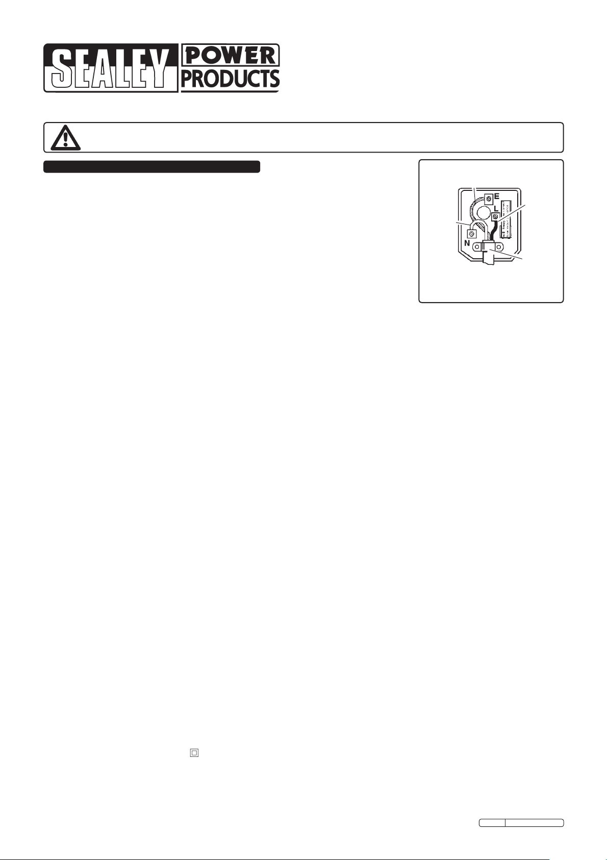
WARNING! Ensure you have read and understood and
adhere to Section 1 safety instruction. DO NOT vacuum
hazardous substances. Use of an incorrect filter will
invalidate your warranty.
Ensure you are using the personal protection items
appropriate to the task before operating the unit and before
opening the vacuum system drum.
7.1. PREPARATION FOR USE.
7.1.1 Check that the filter to be used is in good condition.
7.1.2. Check the vacuum system and attached tools are in good
working order and condition and all air and electrical
connections are sound.
7.1.3 Check that the switches are in the correct positions as
described in section 4.2 and 4.3.
7.1.4 Turn the electrical mains power on and the external air supply.
7.2. OPERATING THE DUST FREE SYSTEM.
IMPORTANT: Ensure fine particle filter is fitted.
7.2.1 Make the tool ready for use and operate the tool which in
turn will automatically activate the dust vacuum system.
Whilst performing the task the vacuum system will draw the
dust up into the unit.
7.2.2 When you turn off the tool, the vacuum system will continue
to operate for approximately a further 10 seconds
drawing up any remaining dust.
7.2.3 When the task is complete, unplug the unit from the mains
power supply. Turn off the source of the air supply and
disconnect the unit from the air supply.
7.3. USING THE UNIT AS AN ORDINARY VACUUM CLEANER.
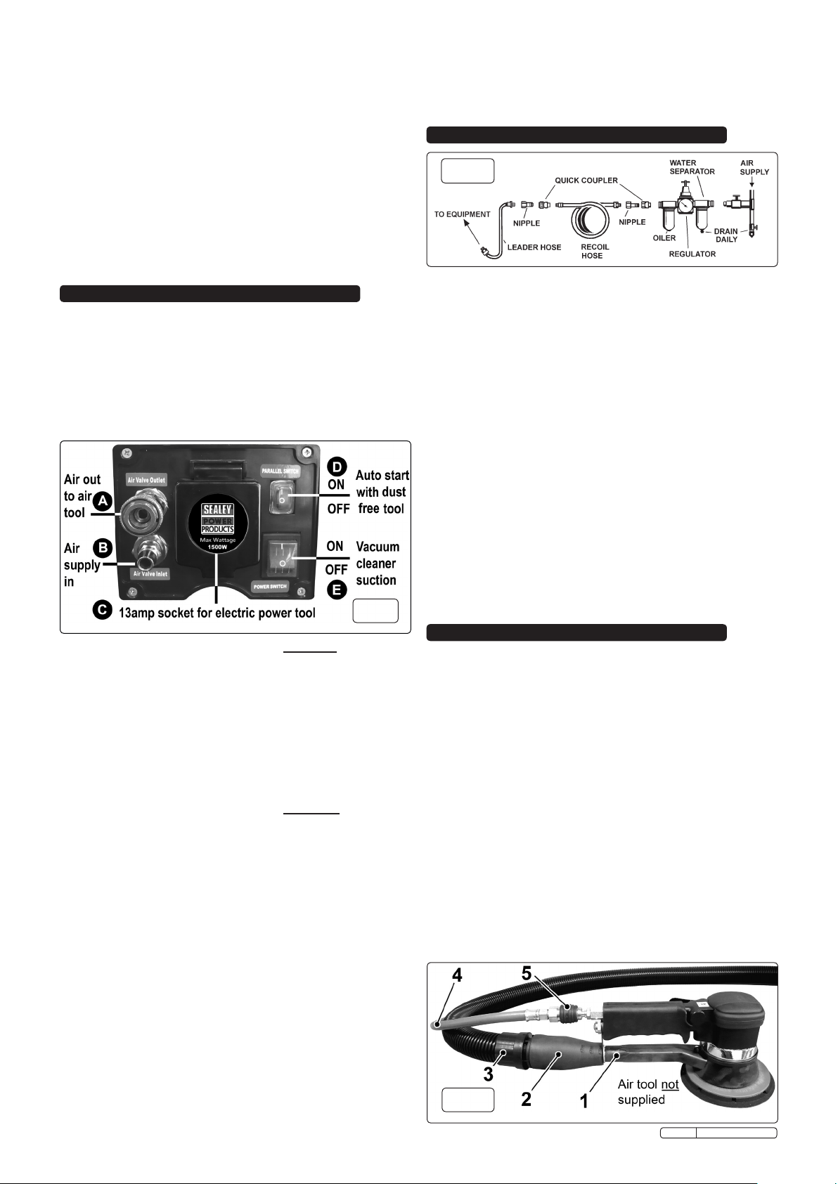
7.3.1 SWITCH OFF THE AUTO START FUNCTION. To use the
unit as a standard wet or dry vacuum cleaner without a dust
free tool attached the Parallel Switch (auto start), (see fig.3D),
must be in the OFF position. Press the lower part of the
switch ("O") to turn it off.
NOTE: The main on/off switch will not work if the Auto Start
switch is left on.
7.3.2 DISCONNECT TOOLS/AIRLINES. Disconnect any airlines or
airtools ensuring that the source of the air supply is off first.
Disconnect the flexible hose from any airtool dust port and
remove the rubber adaptor. Unplug any electric tools from
the front panel of the unit. Tidy away any airlines or
unwanted tools to maintain a safe working area.
7.3.3 FIT THE CORRECT FILTER. Undo the clasps on either side of
the drum. Remove the power head and fit the required filter.
DRY VACUUM. Fit the disposable filter bag over the suction
inlet inside the drum. Alternatively fit cartridge filter down over
the filter basket and push fully home. Stretch the wire
retainer into place over the filter. When the cartridge filter is
fitted dust and debris are collected in the drum.
WET VACUUM. Fit the cartridge filter only. Reposition the
power head onto the drum body, and refasten the clasps.
7.3.4 CONNECT THE FLEXIBLE HOSE. Insert the larger end of
the flexible hose into the front inlet on the drum container and
push home until it clicks.
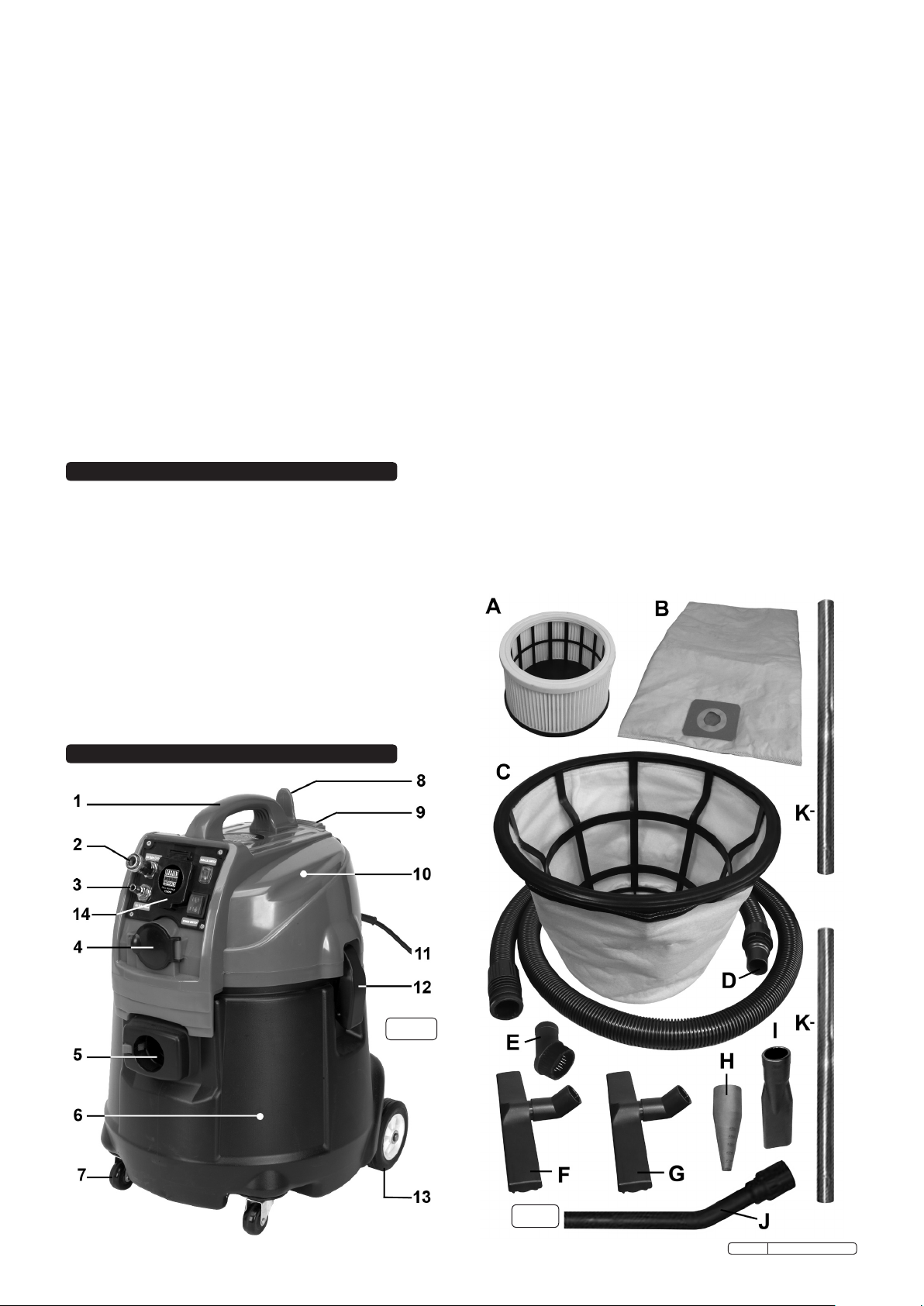
7.3.5 CONNECT THE REQUIRED ATTACHMENTS. Attachments
such as the crevice tool (fig.2-I) and the brush (fig.2-E) can be
pushed directly on to the end of the flexible hose. For floor work
push the bent connector (fig.2-J) onto the flexible tube and then
use the metal extension tubes (K) and either the dry floor tool
(F) or the wet floor tool (G).
7.3.6 CONNECT TO MAINS POWER SUPPLY. Insert the 13amp
plug into the mains power supply.
7.3.7 TURN ON THE UNIT. Press the upper part ("I") of the
Vacuum on/off switch (see fig.3E) to start the vacuum cleaner.
7.3.8 When you have completed vacuuming, press the switch to ‘Off’.
7.3.9 NOTES REGARDING WET VACUUMING:
WARNING! DO NOT vacuum solvents, explosives,
inflammable and/or hazardous liquids such as petrol, oil,
spirits, paint, thinners, acids etc.
7.3.10 To vacuum large quantities of liquid, from a sink or tank etc,
do not immerse the nozzle completely in the liquid, leave a
gap at the top of the nozzle opening to allow an air inflow.
The machine is fitted with a float valve which stops the
suction action when the tank has reached its maximum
capacity. The user will notice an increase in motor speed.
When this happens, turn off the machine, disconnect from
power supply, remove the power head from the container
and empty the liquid into a suitable receptacle or drain. To
continue vacuuming, refit the power head and proceed. After
wet vacuuming, turn the machine off and unplug from power
supply. Empty the container and clean and dry the inside and
outside before storage.
Remember! A dry cartridge filter must be fitted before dry
vacuuming again.
WARNING! Not designed for liquid storage. Always
empty liquids after use and before storing.
7.4. BLOWING
7.4.1 Open the hinged access hatch on the power head and push
the large end of the flexible hose into the blowing port
against spring pressure until it latches.
7.4.2 Ensure the power switch is turned off and plug in the power
supply.
7.4.3 Switch on the power (position ‘I’).
7.4.4 The unit will now blow through the hose and can be used to
clear obstructions within the pipe.
WARNING! If after a few seconds the hose is still blocked turn
of the unit and clear the hose manually.
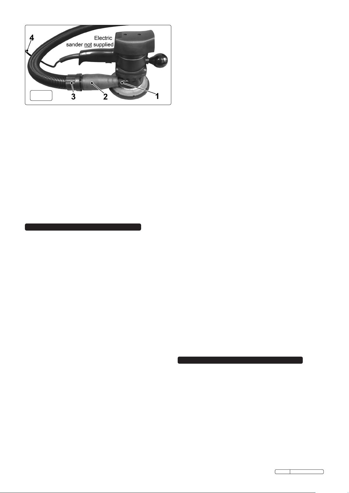
6.2. Connecting an Electrically operated tool. (See fig.6)
6.2.1 FIT THE FINE PARTICLE FILTER. Undo the clasps that hold
the power head onto the drum (see fig.1-12) and lift off the
head. Remove the cartridge filter if fitted and drop the large
fine dust filter into the drum so that it rests on the rim of the
container. Replace the power head and secure it with the
clasps.
6.2.2 TRIM RUBBER ADAPTOR. Take the dust free rubber
adaptor (see fig.5-2) and trim the coned end with a sharp
knife so that it is a tight fit onto the dust extraction port on the
electric tool (see fig.5-1).
6.2.3 CONNECT FLEXIBLE HOSE. Insert the smaller end of the
flexible hose fully into the rubber adaptor (see fig.5-3). Insert
the larger end of the flexible hose into the suction port
on the front of the drum (see fig.1-5).
6.2.4 PLUG IN ELECTRIC TOOL. Take the plug at the end of the
tool cable (see fig.5-4) and insert it into the 13amp socket in
the center of the control panel.
6.2.5 SET UP SWITCHES FOR DUST FREE OPERATION. See
section 4.3.
8.1 GENERAL MAINTENANCE.
8.1.1 Ensure the machine is unplugged from the power supply.
8.1.2 Disconnect the hose from the container.
8.1.3 Undo the clasps and remove power head from the
container.
8.1.4 Clear out any dirt or debris from the container and hose.
8.1.5 If changing from wet to dry use ensure that the inside of the
drum is thoroughly dry before commencing work.
8.2 DUST COLLECTION BAG.
8.2.1 The bag is designed for single use. Once it is full it should be
disposed off and a new bag fitted.
8.3 CARTRIDGE FILTER MAINTENANCE.
8.3.1 Handle the filter carefully when cleaning or installing.
8.3.2 Carefully remove the cartridge filter and inspect it for
damage. A filter that has small holes or tears in it will not
perform efficiently and should be replaced.
8. MAINTENANCE
fig.6
Original Language Version DFS55 Issue: 2 - 17/02/10

Cartridge Filter.................................Model No. DFS55.02-42
Fine Particle Filter ................................Model No. DFS55.04
Dust Collection Bag.........................Model No. DFS55.05-18
IMPORTANT! IF THE MACHINE IS USED WITHOUT A
FILTER FITTED THE MOTOR WILL BURN OUT
EVENTUALLY AND YOUR GUARANTEE WILL BE
INVALIDATED. ALWAYS KEEP SPARE FILTERS HANDY.
8.3.3 To clean a dry filter, tap it inside a waste bin.
8.3.4 To clean a wet filter rinse it with water. If the dirt is stubborn
the filter can be brushed with a plastic brush and rinsed with
water again. Do not use a metal wire brush as this will
damage the filter.
8.4 FINE PARTICLE FILTER MAINTENANCE.
8.4.1 Clean in the same way as the cartridge filter. If the filter is
rinsed in water it must be thoroughly dry before it can be
used again.
NOTE: Blocked filters and/or over filled bags may damage the motor
and will invalidate your warranty.
WARNING! DO NOT operate the system without a filter
or dust bag. Always ensure you use authorised spares,
filters and bag. Contact your Sealey dealer for details.
WARNING: The warnings, cautions and instructions
discussed in this instruction manual cannot cover all
possible conditions and situations that may occur. It
must be understood that common sense and caution are
factors which cannot be built into this product, but must
be applied by the operator.
8.5 AIR INLET FILTER. (See fig.7)
8.5.1 The air inlet filter should be cleaned on a regular basis to
ensure efficient operation of the unit.
8.5.2 Remove the air filter cover (C) from the power head by
pressing the release button (D) and tipping the cover
backwards and lifting it off.
8.5.3 Pull out the filter holder (B) and remove the foam filter (A).
8.5.4 Wash the foam filter in warm soapy water to clean it. Rinse it
in clear water, squeeze thoroughly and leave to dry.
8.5.5 Insert the foam filter back into the filter holder and insert the
holder into the aperture in the head. Push fully home.
8.5.6 Insert the two tabs on the bottom of the filter cover into the
slots in the bottom of the filter aperture. Hinge the cover
forwards and snap it into place.
PROBLEM CAUSE SOLUTION
1)
Cleaner
will not
operate
1a) No power supply Check supply
1b) Faulty power cable,
switch or motor
Check and repair or replace
faulty item
1c) Container full of
liquid
Empty container
2) Dust
comes
from the
motor
cover
2) Cartridge lter
missing or damaged
Fit or replace cartridge lter
3)
Reduced
efciency
and
increased
motor
speed/
vibration.
3a) Dust container full Empty container
3b) Filter clogged Clean or replace cartridge
lter
3c) Nozzle, hose or
container inlet blocked
Check nozzle, hose &
container inlet for blockage
fig.7
10. CONSUMABLES
9. TROUBLESHOOTING
NOTE: It is our policy to continually improve products and as such we reserve the right to alter data, specifications and component parts without prior notice.
IMPORTANT: No liability is accepted for incorrect use of this product.
WARRANTY: Guarantee is 12 months from purchase date, proof of which will be required for any claim.
INFORMATION: For a copy of our latest catalogue and promotions call us on 01284 757525 and leave your full name and address, including postcode.
01284 757500
01284 703534
sales@sealey.co.uk
Sole UK Distributor, Sealey Group,
Kempson Way, Suffolk Business Park,
Bury St. Edmunds, Suffolk,
IP32 7AR
www.sealey.co.uk
Web
email
Original Language Version DFS55 Issue: 2 - 17/02/10
Table of contents
Other Sealey Vacuum Cleaner manuals

Sealey
Sealey CPV72 User manual

Sealey
Sealey VMA92.V2 User manual

Sealey
Sealey PC300SDAUTO.V3 User manual

Sealey
Sealey GV180WM User manual

Sealey
Sealey PC477 User manual

Sealey
Sealey CP20VCV User manual

Sealey
Sealey PC200SDAUTO User manual

Sealey
Sealey CPV144.V2 User manual

Sealey
Sealey PC200A User manual

Sealey
Sealey POWERCLEAN COMBI PC118 User manual

Sealey
Sealey DFS31A.V2 User manual

Sealey
Sealey PC700 User manual

Sealey
Sealey CPV144 User manual

Sealey
Sealey VMA913 User manual

Sealey
Sealey CPV72 User manual

Sealey
Sealey PC380M110V User manual

Sealey
Sealey PC195SD.V2 User manual

Sealey
Sealey Quality MACHINERY SM46.V3 User manual

Sealey
Sealey PC150A User manual

Sealey
Sealey PC20LN User manual